Week 4 — Embedded Programming
Introduction
This week focused on embedded programming — writing code that runs directly on a microcontroller to control physical hardware in the real world. Unlike software running on a regular computer where an operating system manages memory, processes, and hardware access for you, embedded code runs on bare metal — it is the only program on the chip, and it has direct, unmediated control over every pin, register, and peripheral. This direct relationship between software and hardware is what makes embedded programming both powerful and demanding at the same time.
The project I built this week is a stepper motor control system — a key subsystem of my larger robot arm project. The goal was straightforward but technically rich: use an Arduino UNO microcontroller to send precise electrical pulses through a motor driver circuit, causing a NEMA 17 stepper motor to rotate by exactly controlled amounts in both directions. This demonstrates the core embedded programming skill of controlling a physical output device (the motor) through a precisely timed digital signal sequence generated entirely in software.
The system consists of four main hardware components: an Arduino UNO microcontroller, a TB6560 stepper motor driver, a NEMA 17 stepper motor, and a WANPTEK DC bench power supply. Each component plays a distinct and essential role, and understanding why each one is necessary — not just how to wire it — is the real engineering learning of this week. The path from a blank code editor to a spinning motor involves understanding microcontroller architecture, driver circuit theory, motor physics, toolchain configuration, and serial communication protocols all working together.
Component 1 — Arduino UNO
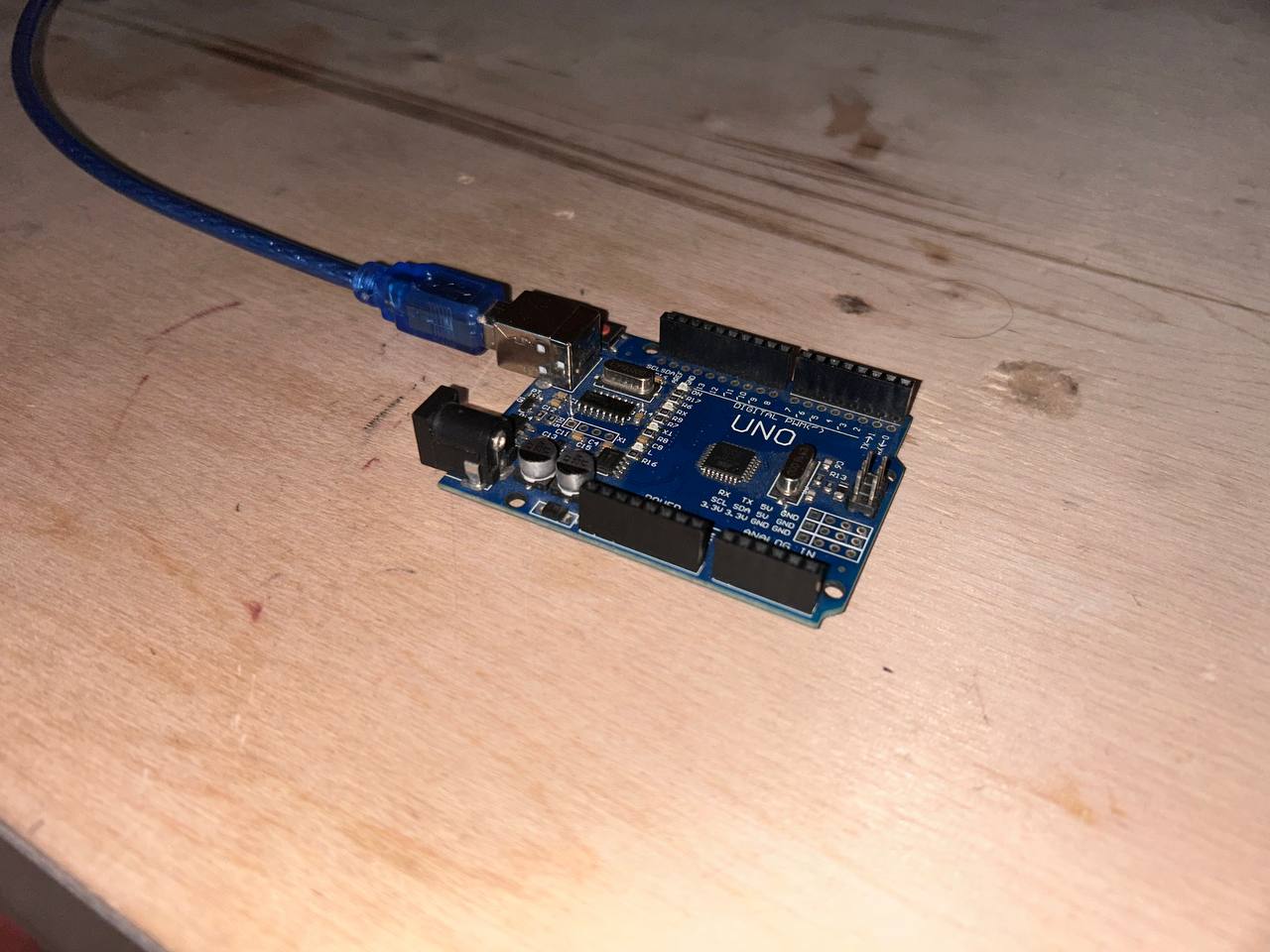
The Arduino UNO is the central brain of this entire system. It is a development board built around the ATmega328P — an 8-bit AVR RISC microcontroller manufactured by Microchip Technology (formerly Atmel). The board was first released in 2010 and has since become the most widely used microcontroller development board in the world for education, prototyping, and hobby electronics. The reason for its enduring popularity is not raw performance — there are far more powerful microcontrollers available for the same price — but rather its combination of simplicity, excellent documentation, massive community support, and the Arduino IDE software ecosystem that makes embedded programming accessible to beginners without sacrificing capability for more advanced users.
The ATmega328P chip runs at 16 MHz using an external crystal oscillator soldered directly onto the UNO board. The external crystal is important — it provides a stable, accurate clock reference that is critical for generating precise timing signals. An internal RC oscillator (also available on the ATmega328P) is less accurate and drifts with temperature changes, which would cause timing errors in the stepper motor control pulses. For motor control, timing precision directly affects motor speed accuracy — if the clock is 1% off, the motor runs 1% too fast or too slow.
The ATmega328P has the following hardware resources that are relevant to this project:
-
32 KB of Flash memory — This is where the compiled program is stored permanently. Even when power is removed and restored, the flash retains the code. The Arduino bootloader occupies 512 bytes of this flash, leaving 31,744 bytes (approximately 31.5 KB) available for user programs. The bootloader is a small program pre-loaded at the factory that listens for upload commands on the UART immediately after reset — this is what allows code to be uploaded via USB without a separate programming hardware device.
-
2 KB of SRAM — Static RAM is the working memory where variables, function call stack frames, and runtime data live during program execution. It is volatile — all contents are lost the moment power is removed. At only 2048 bytes, SRAM is the most constrained resource on the ATmega328P. Running out of SRAM causes mysterious, hard-to-debug crashes because the stack collides with heap-allocated data. Careful memory management is essential for complex programs.
-
1 KB of EEPROM — Electrically Erasable Programmable Read-Only Memory. Like flash, EEPROM is non-volatile and retains data through power cycles. Unlike flash, it can be written byte-by-byte from user code using the Arduino
EEPROMlibrary. This is useful for storing configuration settings, calibration values, or accumulated position counts that must survive power-off. -
14 digital I/O pins (pins 0–13) — Each pin can be individually configured as either an input (to read external signals) or an output (to drive signals to external circuits). As outputs, pins can source or sink up to 40mA at 5V. Pins 3, 5, 6, 9, 10, and 11 additionally support hardware PWM (Pulse Width Modulation) at 8-bit resolution (0–255 duty cycle values) using the onboard hardware timers. In this project, pins 3, 4, and 5 are used as digital outputs for the STEP, DIR, and ENABLE signals to the TB6560 driver.
-
6 analog input pins (A0–A5) — Connected to a 10-bit successive-approximation ADC (Analog to Digital Converter) that converts voltages from 0–5V into digital integers from 0 to 1023. The ADC has a single conversion time of approximately 100 microseconds. Not used in this basic motor control project, but essential for future sensor integration.
-
Hardware UART (pins 0 and 1) — A dedicated serial communication peripheral for asynchronous serial data exchange. The Arduino's
Serial.begin(),Serial.print(), andSerial.read()functions use this hardware UART. On the UNO, the UART connects through the onboard USB-to-serial bridge chip to the USB connector, creating the virtual serial port used for both uploading code and for the Serial Monitor debugging tool. -
Hardware SPI (pins 10–13) — Synchronous serial communication protocol supporting high-speed data transfer to devices like SD cards, displays, and sensor modules.
-
Hardware I2C (pins A4 and A5) — Two-wire serial protocol for connecting multiple sensors, displays, and peripherals with just two signal wires.
The blue USB-B cable visible in the photo connects the Arduino to the laptop. This USB connection simultaneously serves two purposes: it provides 5V power to the Arduino board (the onboard LDO voltage regulator maintains 5V from the USB's 5V bus), and it creates a virtual serial port through the CH340G USB-to-UART bridge chip soldered near the USB connector. This virtual serial port appears as /dev/ttyUSB0 on Linux, and the Arduino IDE uses it for both uploading compiled programs via the bootloader and for real-time serial debugging via the Serial Monitor.
Why Arduino UNO is the Right Choice for This Project
The Arduino UNO was chosen for this stepper motor control project for several specific technical reasons, not just because it is popular.
The most important reason is the 5V logic level. The TB6560 stepper motor driver used in this project expects 5V HIGH signals on its STEP, DIR, and ENABLE inputs. The ATmega328P on the Arduino UNO operates at 5V, making its output pins directly compatible with the TB6560 inputs — no level-shifting resistor networks or buffer chips are needed. Many modern microcontrollers like the ESP32, Raspberry Pi Pico, and STM32 operate at 3.3V. Connecting a 3.3V output directly to a 5V input can cause unreliable logic HIGH detection, because a 3.3V signal may not reach the 5V device's minimum HIGH threshold voltage (typically 0.7 × VCC = 3.5V for a 5V device). A dedicated level-shifter would be needed, adding complexity and potential failure points.
The second reason is programming simplicity without sacrificing capability. The Arduino IDE wraps the entire AVR-GCC toolchain into a simple Install-and-upload workflow. Without Arduino, programming the ATmega328P directly requires installing avr-gcc and binutils separately, writing makefiles to configure the compiler flags, understanding the AVR memory model (Harvard architecture with separate flash and SRAM address spaces), and running avrdude from the command line with the correct -p, -c, -P, and -U flags. Arduino automates all of this. For a week focused on learning embedded programming concepts, not fighting toolchain configuration, Arduino is the pragmatic choice.
Arduino UNO vs Other Development Boards — Detailed Comparison
| Feature | Arduino UNO | ESP32 DevKit | Raspberry Pi Pico | STM32 Blue Pill | ATtiny85 |
|---|---|---|---|---|---|
| Core architecture | 8-bit AVR RISC | 32-bit Xtensa LX6 dual-core | 32-bit ARM Cortex-M0+ dual-core | 32-bit ARM Cortex-M3 | 8-bit AVR RISC |
| Clock speed | 16 MHz | Up to 240 MHz | Up to 133 MHz | 72 MHz | 8 or 16 MHz |
| Program flash | 32 KB | 4 MB | 2 MB | 64 KB | 8 KB |
| SRAM | 2 KB | 520 KB | 264 KB | 20 KB | 512 bytes |
| EEPROM | 1 KB | None (use flash emulation) | None | None | 512 bytes |
| Wi-Fi | None | 802.11 b/g/n built-in | None (Pico W version has it) | None | None |
| Bluetooth | None | BT 4.2 + BLE built-in | None (Pico W has BLE) | None | None |
| Operating voltage | 5V | 3.3V | 3.3V | 3.3V | 1.8–5.5V |
| Digital I/O pins | 14 | Up to 34 | 26 | 32 | 6 |
| Analog inputs | 6 × 10-bit | 18 × 12-bit | 3 × 12-bit | 10 × 12-bit | 4 × 10-bit |
| Hardware PWM channels | 6 | 16 | 16 | Many | 2 |
| USB programming | Via CH340 bootloader | Native USB or UART | Native USB | Via ST-Link programmer | Via ISP programmer |
| Price (approximate) | $5 USD | $8 USD | $4 USD | $3 USD | $1.50 USD |
| Beginner-friendly | Excellent | Moderate | Moderate | Difficult | Very difficult |
| 5V I/O (TB6560 compatible) | Yes, natively | No — needs level shifter | No — needs level shifter | No — needs level shifter | Yes, natively |
| Arduino IDE native support | Yes, out of the box | Yes, via board manager | Yes, via board manager | Limited, third-party | Yes, via board manager |
| Available library ecosystem | Largest | Very large | Growing | Moderate | Limited |
For this specific project — generating 5V STEP/DIR pulses at 1kHz to control a TB6560 driver, which requires no internet connectivity, no high-speed processing, and no analog precision — the Arduino UNO is the ideal tool. Its 5V output, simple toolchain, and native serial port make it the path of least resistance from idea to working hardware.
Component 2 — TB6560 Stepper Motor Driver
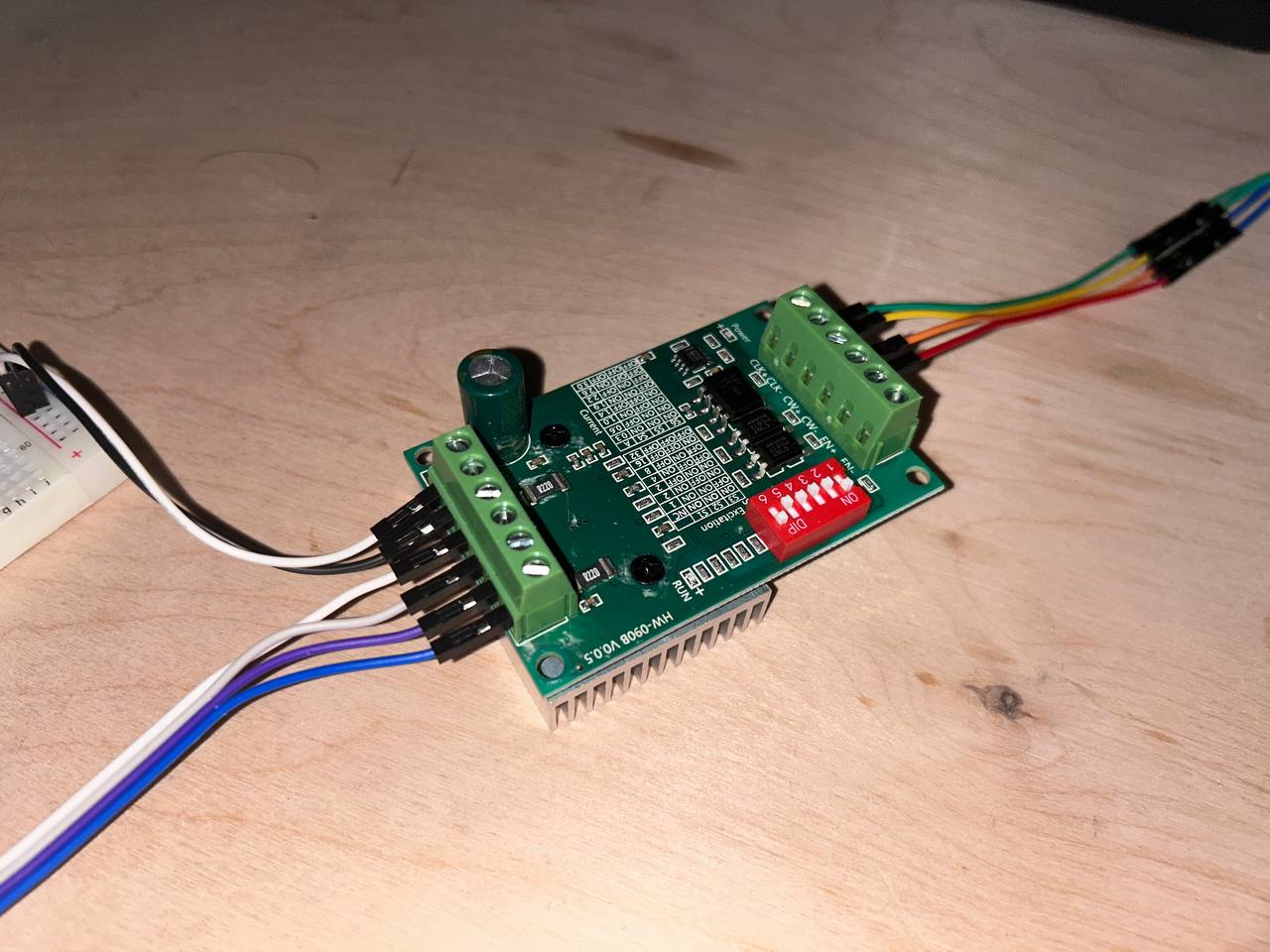
The TB6560 stepper motor driver board (model HW-0908 V0.5) is the power interface between the Arduino's weak logic signals and the high-current demands of the NEMA 17 motor. This component is absolutely non-negotiable in the circuit — without it, the motor simply cannot be connected to the Arduino. Understanding why requires understanding both what the motor needs and what the Arduino can provide.
A bipolar stepper motor like the NEMA 17 works by rapidly switching current through two sets of internal coils (Coil A and Coil B) in a specific repeating sequence. The magnetic fields created by these coils attract and repel the motor's permanent magnet rotor, pulling it from one angular position to the next in precise 1.8° increments. The current required to create sufficient magnetic field strength to actually move and hold the rotor against mechanical load is typically 1.5 to 2 amperes per coil for a NEMA 17. Both coils are energized simultaneously, so the total motor current draw during operation is 3 to 4 amperes.
Now consider what the Arduino UNO can provide: each GPIO pin can source or sink a maximum of 40 milliamperes at 5 volts, with a total board current limit of 200mA for all pins combined. This is between 37 and 100 times less current than the motor needs. Connecting the motor directly to Arduino pins would either produce no movement at all (the tiny current creates insufficient magnetic field to move the rotor) or would instantly destroy the Arduino's output pins by overloading their protection transistors.
The TB6560 solves this fundamental mismatch by acting as a power amplifier. It receives the Arduino's low-power 5V logic signals (STEP, DIR, ENABLE) and uses them to control high-power transistors (organized as two H-bridge circuits, one per motor coil) that switch the full 12V/1.5A motor current from the external power supply through the motor coils in the correct sequence. The Arduino tells the driver what to do; the driver does the actual electrical work.
The TB6560 integrated circuit itself is a Toshiba-designed monolithic bipolar stepping motor driver IC that integrates two H-bridge circuits, current sensing, thermal protection, and microstepping control all in one package. Its key specifications are:
- Output current: up to 3.5A peak per channel
- Supply voltage range: 10V to 35V for motor supply
- Logic voltage: 3.3V to 5V compatible inputs
- Microstepping: supports full step (1:1), half step (1:2), quarter step (1:4), and eighth step (1:8) modes
- Built-in protections: thermal shutdown at approximately 150°C junction temperature, overcurrent protection, undervoltage lockout
Physical features visible in the photo and their functions:
The green screw terminal blocks on the left edge accept the four motor coil wires. Coil A has two wires (A+ and A−) and Coil B has two wires (B+, and B−). These are clamped by tightening small screws — a secure mechanical connection that will not vibrate loose during motor operation, unlike push-in connectors. The motor terminal labels are printed on the PCB silkscreen layer for reference.
The green screw terminal block on the right edge (partially visible) accepts the external power supply connections: VIN+ (positive, 12V from the bench supply) and VIN− (negative, 0V/GND reference from the bench supply).
The red DIP switch bank labeled 1 through 6 configures the driver's operating mode. Switches 1 and 2 select the current decay mode — slow decay keeps current flowing during the off-time (smoother but more heat), fast decay drops current quickly (more efficient but potentially noisier). Switches 3, 4, and 5 set the microstepping resolution. The configuration table is printed on the PCB silkscreen in tiny text. In this project, the switches are set for half-step mode (400 steps per revolution) giving smoother motor motion than full-step mode.
The large green cylindrical electrolytic capacitor near the center of the board is a bulk decoupling capacitor for the motor power supply rail. When the H-bridge transistors switch on and off at high frequency, they create very fast current transients on the 12V supply line. Without this capacitor, these transients appear as voltage spikes that can reach 20–30V even from a regulated 12V supply — well above the TB6560's maximum supply voltage rating. The capacitor absorbs these spikes, clamping the voltage to a safe level and preventing damage to the driver chip.
The aluminum heat sink fins on the underside of the board are for thermal management. At 1.5A motor current, the TB6560 chip dissipates approximately 1.5–2.5 watts as heat due to the resistive losses in its internal transistors. The thermal resistance of the chip's package to ambient air is high enough that without a heat sink, the junction temperature would exceed the 150°C thermal shutdown threshold within minutes of continuous operation. The heat sink increases the surface area for convective heat transfer to the air, keeping the chip cool enough for continuous use.
The signal input header (the row of female pin sockets in the center-left of the board) accepts the jumper wires coming from the Arduino. This is where the STEP, DIR, ENABLE, and GND signals connect. The header pins are labeled on the silkscreen.
Complete wiring between Arduino UNO and TB6560:
| Arduino UNO Pin | TB6560 Terminal Label | Signal | Electrical Description |
|---|---|---|---|
| Digital Pin 3 | CLK / STEP | Step pulse | Rising edge triggers one motor step |
| Digital Pin 4 | CW/CCW / DIR | Direction | 5V HIGH = clockwise rotation |
| Digital Pin 5 | EN / ENABLE | Enable | 0V LOW = driver active, 5V HIGH = motor free |
| GND | GND | Common ground | Shared voltage reference — absolutely required |
The shared ground connection is the most commonly misunderstood wiring detail in mixed-power electronics systems. The Arduino is powered from USB (5V), and the TB6560 motor section is powered from the bench supply (12V). These are two completely separate power sources with no electrical relationship to each other. The STEP signal on Arduino Pin 3 is 5V relative to Arduino's GND. But the TB6560 sees this voltage relative to its own GND terminal. If Arduino GND and TB6560 GND are not connected, the TB6560 has no reference point to interpret the STEP signal — it could measure it as 0V, 5V, −7V, or any random value depending on stray electrical coupling. Connecting the two GND terminals establishes a common 0V reference that both systems measure voltages relative to, making the logic signals interpretable.
Component 3 — NEMA 17 Stepper Motor
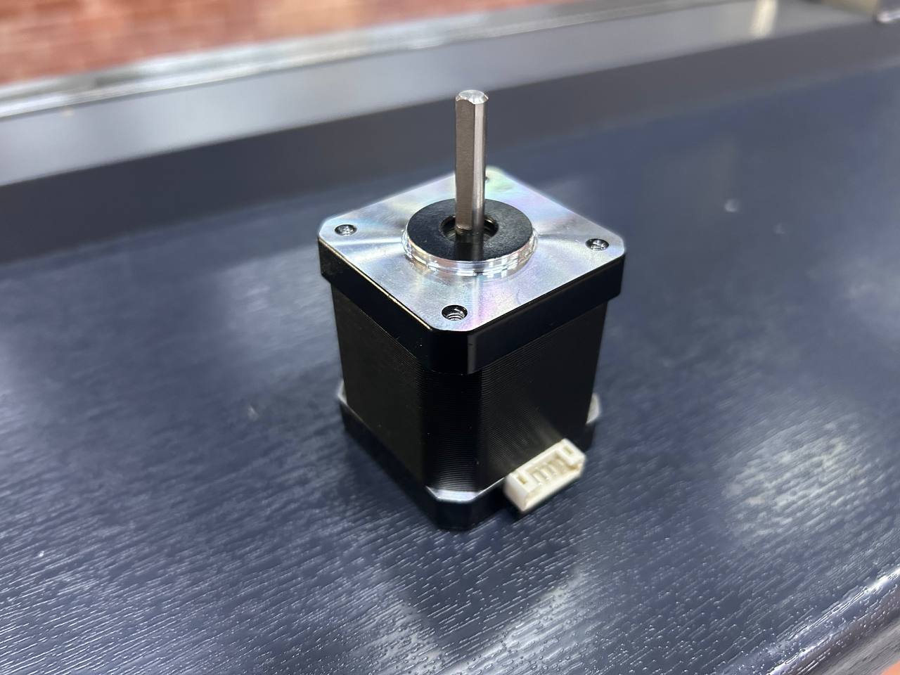
The NEMA 17 bipolar stepper motor is the actuator that physically converts the electrical energy from the TB6560 driver into precise mechanical rotation of the robot arm joints. The name "stepper" refers to the motor's fundamental operating principle — instead of spinning continuously like a DC motor, it moves in discrete, fixed angular increments called steps. Each step is exactly 1.8 degrees for this motor, which means 200 steps complete a full 360° revolution.
The term "NEMA 17" refers to a mechanical mounting standard defined by the National Electrical Manufacturers Association (NEMA). Specifically, it defines the face plate dimensions: 42.3 × 42.3 mm square mounting face with four M3 mounting holes arranged on a 31mm bolt circle diameter, and a central boss (cylindrical protrusion) of 22mm diameter for motor alignment. This standardized mounting means that any NEMA 17 motor from any manufacturer will physically fit the same motor mount — a significant advantage when sourcing parts for the robot arm project.
The detailed electrical and mechanical specifications of the NEMA 17 used in this project:
- Step angle accuracy: ±5% of 1.8° (non-cumulative) — errors do not accumulate over multiple revolutions
- Rated phase current: 1.5A — the TB6560 is set to approximately this current via its internal current sense resistors
- Phase resistance: approximately 1.5–2.0 Ω per coil — used to calculate the voltage drop across each coil at rated current (V = I × R = 1.5A × 2Ω = 3V, but the driver uses PWM to regulate current precisely regardless of supply voltage)
- Phase inductance: approximately 2.8–3.2 mH — higher inductance limits how quickly current can change in the coil, which limits maximum motor speed
- Holding torque: approximately 40–44 N·cm (4.0–4.5 kg·cm) when coils are fully energized at rated current
- Detent torque: approximately 1.5–2.0 N·cm — the residual torque when coils are de-energized, caused by rotor magnet alignment with stator teeth
- Rotor inertia: approximately 35–68 g·cm² — affects how quickly the motor can accelerate and decelerate
- Shaft diameter: 5mm D-cut — compatible with standard 3D printer pulleys, GT2 belt drive gears, flexible shaft couplings, and other robot arm drive components
- Body dimensions: 42 × 42 × 40mm (W × D × L) for a standard 40mm body length variant
- Number of wires: 4 (two coil pairs, bipolar configuration)
- Operating temperature: -20°C to +85°C ambient
How the stepper motor works internally:
The rotor of a NEMA 17 is a permanent magnet with 50 teeth on each end cap, offset from each other by half a tooth pitch. The stator (the stationary part) has electromagnetic poles with windings that form Coil A and Coil B. By controlling which coil is energized and in which polarity, the electromagnetic field pulls specific rotor teeth into alignment with stator poles.
In full-step mode, the energization sequence cycles through four states: 1. Coil A positive, Coil B positive → rotor aligns to position 0° 2. Coil A negative, Coil B positive → rotor snaps to 1.8° 3. Coil A negative, Coil B negative → rotor snaps to 3.6° 4. Coil A positive, Coil B negative → rotor snaps to 5.4° ...then back to state 1 (now at 7.2° = one full electrical cycle of 4 steps)
Each electrical cycle moves the rotor by 7.2°, and 50 such cycles (200 steps total) complete one mechanical revolution. The TB6560 in half-step mode inserts intermediate states where both coils are energized simultaneously, creating intermediate rotor positions at 0.9° intervals — doubling the position resolution to 400 steps per revolution and making motion appear smoother.
The white JST connector visible at the bottom of the motor body is a manufacturer-added convenience connector. The 4 internal wires of the motor terminate here. To identify which wire belongs to which coil, use a multimeter in resistance mode: two wires of the same coil will read approximately 2Ω between them, while two wires from different coils will read infinite resistance (open circuit). Incorrect coil wiring causes the motor to stutter, vibrate in place, or not move at all — it will not damage anything, but the behavior will be confusing until the wiring is corrected.
Why stepper motors are ideal for robot arm joints:
Unlike DC motors that require encoders to know their position, stepper motors provide inherent open-loop position control. The software maintains a step counter, and because each step moves the motor exactly 1.8° (when not stalling), the current position is always known by counting cumulative steps from a known home position. This eliminates the cost and complexity of rotary encoders for basic positioning applications. The holding torque (40–44 N·cm) keeps the joint locked in position when the motor is stationary and coils are energized, preventing the arm from drooping under gravity. For the robot arm project, these properties make stepper motors the perfect actuator choice for each joint axis.
Component 4 — WANPTEK DC Bench Power Supply
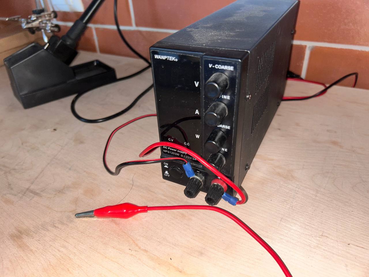
The WANPTEK NPS1203W is a laboratory-grade variable DC bench power supply capable of outputting 0–120V at up to 3A continuous. For this stepper motor project, it is configured to output a stable 12V DC to power the TB6560 driver and the NEMA 17 motor. While 12V and 3A is a small fraction of this supply's total capability, using a proper lab supply rather than a wall adapter or battery provides important advantages: precise voltage adjustment, accurate current limiting, and real-time metering of voltage, current, and power consumption.
Why an external power supply is absolutely necessary:
The NEMA 17 motor draws up to 1.5A per coil × 2 coils = 3A total during full-speed operation with both coils simultaneously energized at rated current. Compare this to what other power sources could provide:
- Arduino USB power: The USB specification limits current to 500mA for USB 2.0 and 900mA for USB 3.0. The motor alone needs 3A — 3.3× to 6× more than USB can provide. Overloading USB causes voltage sag, Arduino resets, computer USB port damage, or fuse tripping.
- Arduino's onboard 5V pin: Limited to 500mA from USB, and the motor also requires 12V, not 5V.
- Arduino's VIN pin with a wall adapter: A 12V wall adapter connected to VIN would be passed through to the TB6560, but the Arduino's onboard voltage regulator would need to regulate 12V down to 5V, and typical wall adapters lack proper current limiting.
- Bench power supply: Provides exactly the right voltage (12V adjustable), proper current limiting (set to 2A for motor protection), stable regulation under varying load, and clear metering showing actual motor power consumption.
Front panel controls and indicators in detail:
The V-COARSE knob (top right) adjusts output voltage in large steps — approximately 1–2V per full rotation of the knob. This is used for quick, rough voltage setting.
The V-FINE knob (second from top right) adjusts voltage in small increments — approximately 0.05–0.1V per full rotation. Using V-COARSE to get close to 12V and then V-FINE to dial in exactly 12.0V gives precise voltage setting without the frustration of overshooting.
The A-COARSE and A-FINE knobs set the current limit in the same coarse/fine arrangement. For this project, the current limit is set to 2.0A — slightly above the motor's rated 1.5A per coil (accounting for the fact that not both coils draw maximum current simultaneously in typical operation), but well below the supply's 3A maximum. The current limit is a critical safety feature: if the motor shaft is mechanically blocked (stall condition), the motor coils become a short circuit through their coil resistance and would draw destructive amounts of current from an unlimited supply. The 2A current limit clamps this to a safe value, protecting both the motor windings (from overheating) and the TB6560 driver (from overcurrent damage) while the stall condition is resolved.
The CV / CC indicator LEDs (Constant Voltage / Constant Current) on the front panel show which regulation mode the supply is operating in. During normal motor operation, the motor draws less than the set current limit, and the supply operates in CV mode (holding output voltage constant at 12V while current varies with motor load). If the motor stalls and current demand rises to the set limit, the supply transitions to CC mode (holding current constant at 2A while voltage sags). The CC LED lighting up is an immediate visual warning that the motor is being overloaded — something is mechanically wrong and needs investigation.
The banana jack output terminals (red = positive, black = negative) are where the red crocodile clip test leads connect. These leads run from the supply to the VIN+ and VIN− screw terminals on the TB6560 driver board, delivering the 12V motor power. For a more permanent installation, the crocodile clips would be replaced with banana plug–to–screw terminal adapters or proper wiring terminated with ferrules.
The ON/OFF switch on the front panel enables and disables the output without disconnecting any wiring — very useful during testing when you want to de-energize the motor quickly without physically unplugging leads. When the output is OFF, the motor coils are de-energized and the motor shaft can be rotated by hand freely. When ON, the coils are energized and the motor holds its position with full holding torque.
Complete System Assembly
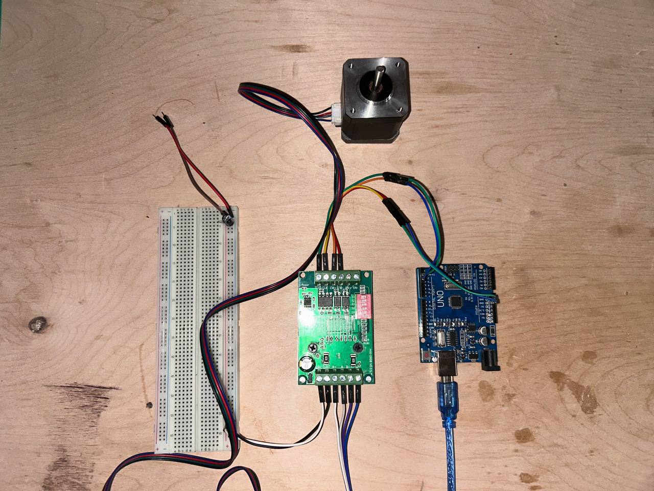
This photo shows the complete assembled system with all four components wired together on the lab workbench, ready for programming. The physical arrangement from the photo:
Top center: The NEMA 17 stepper motor, viewed from the back (shaft pointing away from camera). The four coil wires (black/red/green/blue) run down to the TB6560 driver.
Center: The TB6560 driver board acts as the electrical hub of the system. Motor wires enter from the top via the green terminal block. Signal wires from the Arduino enter from the right via the pin header. Power supply connections (not visible in this photo) enter from the left terminal block.
Right center: The Arduino UNO with the blue USB cable running to the laptop for power and programming. Multiple dupont jumper wires connect from the Arduino's digital pin headers to the TB6560's signal input header.
Left: A full-size 830-tie breadboard. In this system, the breadboard serves as a wiring organization tool — the Arduino's 5V and GND pins connect to the breadboard's power rails, and from there distribute cleanly to multiple connection points. This avoids the fragility of trying to push multiple wires into a single Arduino pin socket simultaneously.
Complete wiring reference table:
| Signal | Source Pin/Terminal | Destination Pin/Terminal | Wire Color | Notes |
|---|---|---|---|---|
| STEP | Arduino Pin 3 | TB6560 CLK/STEP | Yellow | Rising edge = one motor step |
| DIR | Arduino Pin 4 | TB6560 CW/DIR | Green | HIGH=CW, LOW=CCW |
| ENABLE | Arduino Pin 5 | TB6560 EN | Blue | LOW=active, HIGH=coast |
| Logic GND | Arduino GND | TB6560 GND | Black | Critical shared reference |
| Motor power + | PSU + terminal | TB6560 VIN+ | Red (heavy) | 12V, up to 2A |
| Motor power − | PSU − terminal | TB6560 VIN− | Black (heavy) | 0V reference for motor power |
| Coil A+ | TB6560 A+ | NEMA 17 Coil A+ | Black | Bipolar coil A positive |
| Coil A− | TB6560 A− | NEMA 17 Coil A− | Green | Bipolar coil A negative |
| Coil B+ | TB6560 B+ | NEMA 17 Coil B+ | Red | Bipolar coil B positive |
| Coil B− | TB6560 B− | NEMA 17 Coil B− | Blue | Bipolar coil B negative |
The wiring is organized into two entirely separate electrical systems that share only the GND reference:
Low-power logic system (5V, milliamps): Arduino USB → Arduino board → Digital pins 3/4/5 → TB6560 signal inputs. This system handles only information — the STEP, DIR, and ENABLE signals telling the driver what to do.
High-power motor system (12V, amperes): Bench supply → TB6560 power inputs → TB6560 H-bridge → Motor coils → NEMA 17 rotor movement. This system handles the actual energy conversion from electrical to mechanical.
The two systems are electrically isolated from each other except for the shared GND connection, which provides the common voltage reference. This separation is a fundamental principle of power electronics design — logic ground and power ground may physically connect but must be designed as separate current paths to prevent high motor currents from flowing through the logic ground traces and inducing noise into the control signals.
Programming with Arduino IDE
Arduino IDE

Arduino IDE version 2.3.8 was used throughout this project for writing, compiling, and uploading the embedded C++ code to the Arduino UNO. The Arduino IDE is a cross-platform desktop application (available for Windows, macOS, and Linux) that bundles everything needed for Arduino development into a single installation: the Monaco-based code editor with syntax highlighting and autocomplete, the avr-gcc C++ compiler configured specifically for AVR targets, the avrdude upload utility, a library manager for installing third-party libraries, a Serial Monitor for real-time serial debugging, and a Serial Plotter for visualizing numerical data over time.
The Arduino programming model uses a simplified C++ dialect with two mandatory functions. The setup() function runs exactly once immediately after the microcontroller powers on or resets. The loop() function then runs continuously and forever, cycling as fast as the microcontroller can execute — which at 16 MHz with the simple code in this project is approximately every 400 microseconds per full loop iteration.
Behind the scenes, the Arduino IDE invokes the AVR-GCC toolchain:
1. Preprocessing: The .ino file is converted to a valid C++ translation unit with #include <Arduino.h> prepended
2. Compilation: avr-gcc compiles the C++ source to AVR machine code (.o object files) with optimization level -Os (optimize for size)
3. Linking: avr-gcc links all object files and the Arduino core library into a single .elf executable
4. Object copy: avr-objcopy converts the .elf to Intel HEX format (.hex) that avrdude can upload
5. Upload: avrdude communicates with the Arduino bootloader via the serial port to write the .hex file to flash memory
Step 1 — Writing the Code
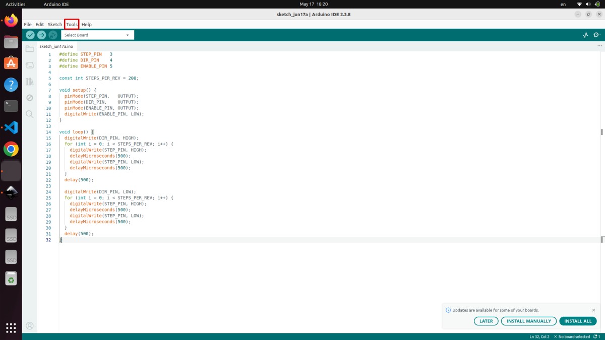
The program (sketch_jun17a.ino) written and visible in the screenshot controls the TB6560 stepper driver by generating precise STEP and DIR pulse sequences. Here is the complete code as written:
#define STEP_PIN    3
#define DIR_PIN     4
#define ENABLE_PIN  5

const int STEPS_PER_REV = 200;

void setup() {
  pinMode(STEP_PIN,   OUTPUT);
  pinMode(DIR_PIN,    OUTPUT);
  pinMode(ENABLE_PIN, OUTPUT);
  digitalWrite(ENABLE_PIN, LOW);
}

void loop() {
  digitalWrite(DIR_PIN, HIGH);
  for (int i = 0; i < STEPS_PER_REV; i++) {
    digitalWrite(STEP_PIN, HIGH);
    delayMicroseconds(500);
    digitalWrite(STEP_PIN, LOW);
    delayMicroseconds(500);
  }
  delay(500);

  digitalWrite(DIR_PIN, LOW);
  for (int i = 0; i < STEPS_PER_REV; i++) {
    digitalWrite(STEP_PIN, HIGH);
    delayMicroseconds(500);
    digitalWrite(STEP_PIN, LOW);
    delayMicroseconds(500);
  }
  delay(500);
}
Complete line-by-line explanation:
#define STEP_PIN 3 — The C preprocessor (which runs before the compiler) replaces every occurrence of the text STEP_PIN in the source code with the literal number 3. This is a compile-time substitution — it costs zero flash, zero SRAM, and zero CPU cycles at runtime. Using symbolic names like STEP_PIN instead of bare numbers is a fundamental embedded programming best practice. If the hardware wiring changes and STEP moves from pin 3 to pin 6, only this one #define line needs updating rather than every line in the code that references pin 3.
#define DIR_PIN 4 — Same principle for the direction signal. Pin 4 drives the TB6560's CW/CCW (clockwise/counter-clockwise) input.
#define ENABLE_PIN 5 — Pin 5 controls the TB6560's ENABLE input. Active LOW: pulling this pin LOW enables the driver (motor coils energized, motor holds position and responds to steps), pulling HIGH disables the driver (coils de-energized, motor shaft rotates freely by hand).
const int STEPS_PER_REV = 200 — Declares an integer constant with value 200. The const keyword tells the compiler this value never changes, allowing it to be stored in flash rather than SRAM (saving precious RAM). 200 comes from the motor's step angle: 360° ÷ 1.8° per step = 200 steps per revolution. This constant is used in the for-loop as the iteration count to measure exactly one full revolution.
void setup() block — Executes once on power-up or reset:
pinMode(STEP_PIN, OUTPUT) — Configures Arduino digital pin 3 as a push-pull output. Internally, this sets bit 3 of the DDRD register (Data Direction Register for Port D) to 1. Without this call, the pin defaults to high-impedance input mode, where digitalWrite() calls have no effect — the pin floats and cannot drive the TB6560 STEP input reliably.
pinMode(DIR_PIN, OUTPUT) and pinMode(ENABLE_PIN, OUTPUT) — Same configuration for pins 4 and 5.
digitalWrite(ENABLE_PIN, LOW) — Immediately enables the TB6560 driver by pulling pin 5 LOW. This causes the driver to energize the motor coils before any step pulses are sent, so the motor immediately develops holding torque and locks its position. If ENABLE were left HIGH (or pin 5 left unconfigured), the driver would remain disabled, step pulses would be ignored, and the motor would spin freely with no control.
void loop() block — Executes repeatedly forever:
digitalWrite(DIR_PIN, HIGH) — Sets pin 4 HIGH, which commands the TB6560 to rotate the motor clockwise when STEP pulses are received. The TB6560's internal logic samples the DIR pin state each time a rising edge occurs on STEP, so DIR must be stable before the first step pulse. Setting DIR before the loop ensures correct direction for all 200 steps.
The first for loop with int i = 0; i < STEPS_PER_REV; i++ — Iterates 200 times, executing one complete STEP pulse per iteration:
- digitalWrite(STEP_PIN, HIGH) — Pulls pin 3 HIGH, starting the step pulse
- delayMicroseconds(500) — Holds HIGH for 500 microseconds. The TB6560 requires a minimum pulse HIGH time of approximately 2.5µs — 500µs is 200× above this minimum, guaranteeing reliable step detection even with timing jitter from the Arduino's software delays
- digitalWrite(STEP_PIN, LOW) — Pulls pin 3 LOW, ending the step pulse
- delayMicroseconds(500) — Holds LOW for 500µs before the next step
The complete step pulse period is 1000 microseconds (1ms), giving a step frequency of 1000 Hz. At 200 steps per revolution, the motor completes one revolution in exactly 200ms (0.2 seconds), rotating at 300 RPM (5 revolutions per second). This is a moderate speed for a NEMA 17 — well within the motor's capability and comfortable for the TB6560 driver.
delay(500) after the first loop — Pauses for 500 milliseconds (half a second) after completing the clockwise revolution. During this pause the motor holds its position (coils remain energized, DIR and STEP are stable). This pause makes the back-and-forth motion clearly visible and adds mechanical settling time.
digitalWrite(DIR_PIN, LOW) — Changes direction to counter-clockwise for the return trip.
The second for loop — Identical to the first loop but now with DIR LOW. Executes 200 more STEP pulses, rotating the motor back to its starting position.
Final delay(500) — Another half-second pause before the loop repeats. Without this pause, the motor would immediately begin the next clockwise revolution with no visible stop — the pause makes the motion pattern obvious during demonstration.
Step 2 — Selecting the Correct Board
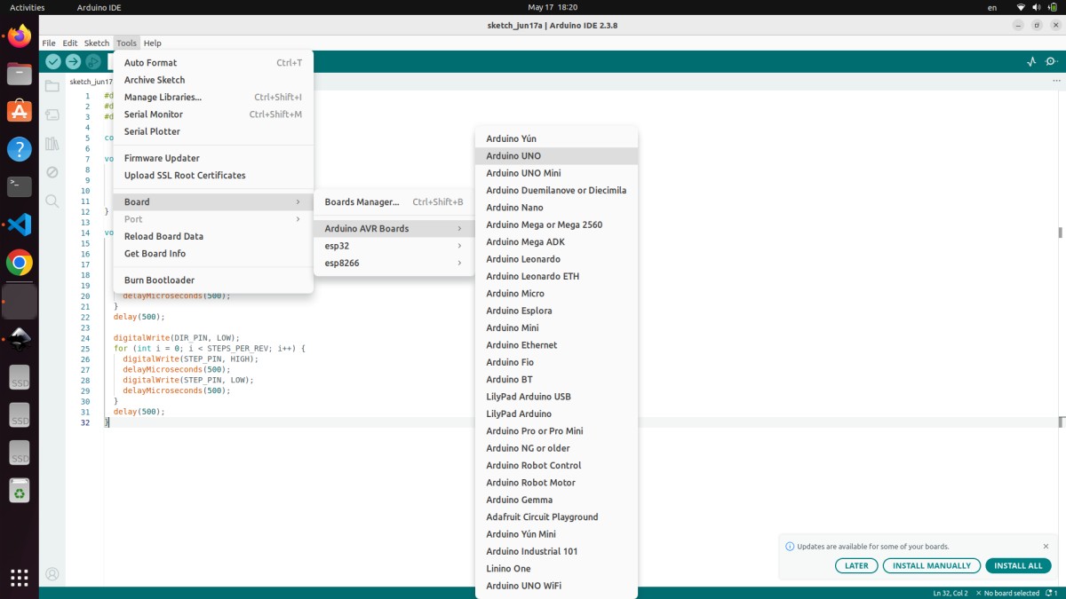
Before the code can be compiled and uploaded, the correct target board must be selected via Tools → Board → Arduino AVR Boards → Arduino UNO. The screenshot shows this menu open with Arduino UNO highlighted and about to be selected. The board list includes many Arduino variants (UNO Mini, Nano, Mega 2560, Leonardo, Micro, etc.) and even third-party boards (ESP32, ESP8266).
The board selection is not merely cosmetic — it configures critical parameters for the compiler and uploader:
MCU target for avr-gcc: Selecting Arduino UNO sets -mmcu=atmega328p in the compiler flags, telling avr-gcc to generate machine code for the ATmega328P's specific instruction set, register addresses, and memory map. Compiling for ATmega2560 (Arduino Mega) produces code with different register addresses that would be completely non-functional on the ATmega328P.
F_CPU definition: The board definition sets F_CPU=16000000L (16 million Hz), which is compiled into the Arduino core library. All timing functions — delay(), delayMicroseconds(), millis(), micros() — use this value to calculate how many CPU cycles correspond to a given time duration. If the wrong board clock frequency were selected, all timing would be proportionally wrong. Selecting an 8 MHz board definition for a 16 MHz UNO would make delay(1000) produce a 2-second delay instead of 1 second, and the stepper motor would run at exactly half the intended speed.
Bootloader protocol and upload baud rate: The Arduino UNO uses the STK500v1 protocol at 115200 baud for programming communication. Other boards use different protocols (STK500v2 for Mega, AVRISP for direct ISP, Caterina for Leonardo's native USB). Selecting the wrong board causes avrdude to use the wrong protocol, resulting in upload timeout errors even when the cable and port are correct.
Memory size definitions: The board definition specifies FLASHEND=0x7FFF (32KB flash), RAMEND=0x8FF (2KB RAM), and E2END=0x3FF (1KB EEPROM). The IDE uses these values to calculate and display the percentage of flash and RAM used, and to warn if the program exceeds available memory.
Step 3 — Connecting and Selecting the Port
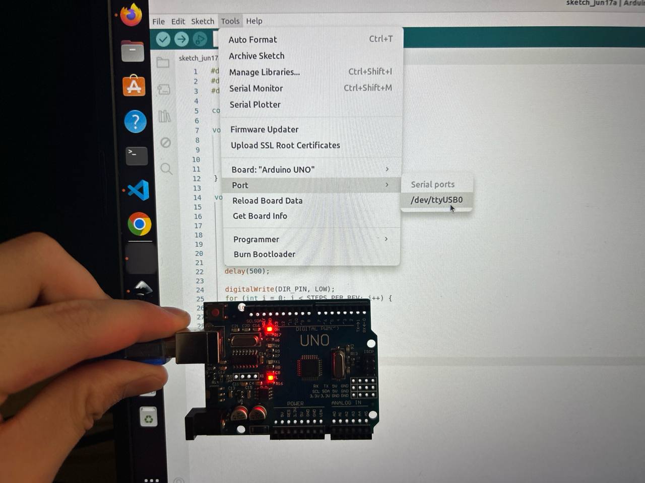
After board selection, the serial communication port must be configured. With the Arduino physically connected via USB, navigate to Tools → Port → /dev/ttyUSB0. The photo shows the Arduino being held in front of the laptop displaying the port selection menu, with the critical /dev/ttyUSB0 option visible. The Arduino's red power LED glows brightly — this is the first hardware confirmation that the board has power and is functioning.
When the Arduino UNO is connected to a Linux computer via USB, the kernel's USB subsystem enumerates the CH340G USB-to-UART bridge chip and creates a character device file at /dev/ttyUSB0. This device file is the communication interface between the Arduino IDE (running on the laptop) and the ATmega328P bootloader (running on the Arduino). The Arduino IDE opens this device at 115200 baud, asserts the DTR (Data Terminal Ready) handshake line, which causes the Arduino's reset filter circuit (a 100nF capacitor connecting DTR through the USB-serial chip's DTR output to the ATmega328P's RESET pin) to briefly pull RESET low, triggering a chip reset that restarts the bootloader.
The red LED visible on the Arduino board is the power indicator LED connected between the 5V rail and GND through a current limiting resistor. It glows whenever the Arduino is receiving USB power. Its brightness and steadiness confirm that the USB cable is carrying data lines (not a charge-only cable), the CH340G bridge chip is operating correctly, and the 5V onboard regulator is maintaining the correct voltage.
A common issue encountered on Linux with CH340G-based Arduino clones is that /dev/ttyUSB0 does not appear in the port menu even when the board is connected. The causes and solutions:
- Missing
dialoutgroup membership: ThettyUSB0device is owned by groupdialoutwith permissions 660. A user not in this group has no access. Fix:sudo usermod -a -G dialout $USERthen log out and back in. - CH340 driver not loaded: On some Linux distributions, the
ch341kernel module may not be loaded automatically. Fix:sudo modprobe ch341or install the appropriate kernel module package. - Cable is charge-only: Many USB cables, especially short micro-USB or USB-B cables sold with accessories, have only VBUS and GND connected with no D+ and D− data lines. The Arduino receives power but is invisible to the USB host. Fix: try a different, known-good USB cable.
- Port in use by another application: If another serial terminal program is connected to
/dev/ttyUSB0, the Arduino IDE cannot open it. Fix: close the other application first.
Step 4 — Uploading and Successful Verification
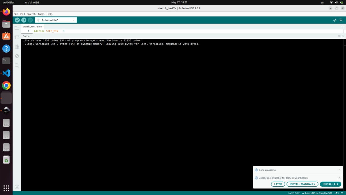
With board set to Arduino UNO and port set to /dev/ttyUSB0, clicking the Upload button (circular right-arrow icon in the toolbar) initiates the compile-and-upload sequence. The output panel at the bottom of the IDE fills with status messages, culminating in the output visible in the screenshot:
Sketch uses 1058 bytes (3%) of program storage space. Maximum is 32256 bytes.
Global variables use 9 bytes (0%) of dynamic memory, leaving 2039 bytes for local variables. Maximum is 2048 bytes.
Done uploading.
Analysis of the compilation output:
Sketch uses 1058 bytes (3%) of program storage space. Maximum is 32256 bytes.
The compiled machine code for the entire motor control program occupies 1058 bytes of the ATmega328P's 32,256 available bytes of user flash. This extreme compactness reflects several facts about the code: it uses no external libraries (no library code is linked in), it uses no String objects or dynamic memory allocation, it performs no floating-point arithmetic (which on the ATmega328P requires a software floating-point library adding 2–4KB of code), and the avr-gcc compiler with -Os optimization removes any dead code and optimizes instruction sequences for minimum size. With 97% of flash still available, there is ample space to add acceleration/deceleration ramp profiles (smooth motor starting and stopping), serial command parsing (to control the motor remotely via USB commands from a computer), multi-axis coordination for controlling multiple motors, or even a simple G-code interpreter.
Global variables use 9 bytes (0%) of dynamic memory, leaving 2039 bytes for local variables. Maximum is 2048 bytes.
Only 9 bytes of the ATmega328P's 2048 bytes of SRAM are consumed by global variables. The three #define constants (STEP_PIN, DIR_PIN, ENABLE_PIN) consume zero SRAM — they are textual substitutions resolved at compile time, not runtime variables. The const int STEPS_PER_REV = 200 is also typically stored in flash by the optimizer rather than SRAM. The 9 bytes are consumed by the Arduino core's internal variables (timer overflow counters for millis(), UART buffer pointers, etc.). The loop variable int i is a stack-allocated local variable that uses 2 bytes of stack during loop execution but is not counted in the global variable total. With 2039 bytes of SRAM free, the code could add large buffers for serial command parsing, motion planning queues, or position tracking arrays for multiple axes.
Done uploading.
This message confirms that avrdude successfully transmitted the 1058-byte program to the ATmega328P's flash memory via the STK500v1 protocol at 115200 baud through the CH340G bridge. Immediately after this message appears, the ATmega328P exits the bootloader and begins executing the uploaded user program — and the NEMA 17 motor immediately begins rotating, confirming the complete signal chain is working correctly: laptop → USB cable → CH340G bridge → UART → ATmega328P bootloader → flash memory → user program → Pin 3/4/5 → TB6560 STEP/DIR/EN → H-bridge transistors → motor coil current switching → NEMA 17 rotor rotation.
ATmega328P Datasheet Overview
The ATmega328P datasheet (Microchip document DS40002061, 660 pages) was reviewed to understand the hardware at a deeper level than the Arduino abstraction exposes. This is an important part of embedded programming education — understanding what the abstractions are hiding gives you the knowledge to optimize, debug, and extend beyond what the abstraction supports.
Section 13 — I/O-Ports (page 86–101): Every I/O pin is controlled through three memory-mapped 8-bit registers accessed at specific AVR I/O register addresses. The DDRx register (Data Direction Register) sets each pin's direction: writing a 1 to a bit sets the corresponding pin as output, writing 0 sets it as input. The PORTx register sets the output state for pins configured as outputs (1=HIGH/5V, 0=LOW/0V) or enables/disables the internal pull-up resistor for input pins. The PINx register, when read, returns the actual current logic level on each pin regardless of the DDRx setting.
Arduino's pinMode(3, OUTPUT) is implemented as:
DDRD |= (1 << 3); // Set bit 3 of Port D direction register to output
Arduino's digitalWrite(3, HIGH) is implemented as approximately:
PORTD |= (1 << 3); // Set bit 3 of Port D output register to HIGH
However, Arduino's digitalWrite() additionally performs pin validation, disables PWM on the pin if active, and handles the pin-to-port-and-bit mapping through a lookup table — all of which adds approximately 50 CPU clock cycles of overhead. Replacing digitalWrite(STEP_PIN, HIGH) with PORTD |= (1 << 3) and digitalWrite(STEP_PIN, LOW) with PORTD &= ~(1 << 3) reduces the per-step pulse generation from ~100 cycles to ~4 cycles, enabling step frequencies from the current ~1kHz up to over 50kHz — dramatically increasing achievable motor speed.
Section 14 — Timer/Counter (page 102–163): The ATmega328P has three hardware timer modules. Timer0 is an 8-bit timer used by Arduino's delay(), millis(), and micros(). Timer1 is a 16-bit timer that can generate PWM on pins 9 and 10 with 10-bit resolution. Timer2 is another 8-bit timer for PWM on pins 3 and 11.
For advanced stepper motor control, Timer1 can be configured to generate periodic interrupts at precise intervals using the CTC (Clear Timer on Compare) mode, triggering an interrupt service routine (ISR) that generates step pulses independently of the main loop. This approach — hardware timer-driven step generation — is what professional stepper motor libraries use. It allows the main loop to handle other tasks (reading sensors, communicating over serial, updating displays) concurrently with smooth, jitter-free motor stepping, without any blocking delay() calls.
Section 19 — USART (page 206–239): The Universal Synchronous/Asynchronous Receiver Transmitter is the hardware peripheral behind Arduino's Serial library. Baud rate is configured by writing to the 16-bit UBRR (USART Baud Rate Register): UBRR0 = (F_CPU / (16UL × baud)) − 1. For 9600 baud at 16 MHz: UBRR0 = (16,000,000 / (16 × 9600)) − 1 = 103. The USART has a two-byte hardware transmit buffer and a one-byte receive buffer, operating independently from the CPU through its own shift register. Data sent with Serial.print() is loaded into the transmit buffer and the USART hardware handles the actual bit timing without further CPU involvement.
Electrical Characteristics (page 400–430): The ATmega328P's absolute maximum ratings include VCC up to 6.0V (permanent damage above this), voltage on any I/O pin up to VCC + 0.5V, maximum DC current per I/O pin 40mA, and total package current (sum of all pins) 200mA. Understanding that 200mA is the total for all pins combined — not 40mA × 14 pins — is critical. If many pins are simultaneously driving LEDs or other loads, the total current must stay below 200mA or the chip's internal metallization can fuse open.
Hero Shot
The complete system assembled and operational. All four components — Arduino UNO, TB6560 driver, NEMA 17 motor, and bench power supply — are connected and the motor is actively rotating under Arduino control. This is the culmination of the week's work: a working embedded system that takes a software program, converts it to precise electrical signals, amplifies those signals to motor-driving power levels, and produces controlled mechanical motion.
Video Demo
[Video demonstration of the NEMA 17 stepper motor rotating one full revolution clockwise, pausing, then one full revolution counter-clockwise, repeating continuously under Arduino control — confirming the complete embedded system is working correctly]
Source Code
// ============================================
// Week 4 — Embedded Programming
// Stepper Motor Control — Arduino UNO + TB6560
// Author: Abdikarim Kamaluly
// Fab Academy 2026 — YuFabLab
// ============================================

#define STEP_PIN    3
#define DIR_PIN     4
#define ENABLE_PIN  5


const int STEPS_PER_REV = 200;
const int STEP_DELAY_US = 500;

void setup() {
  pinMode(STEP_PIN,   OUTPUT);
  pinMode(DIR_PIN,    OUTPUT);
  pinMode(ENABLE_PIN, OUTPUT);

  digitalWrite(ENABLE_PIN, LOW);
}

void loop() {
  digitalWrite(DIR_PIN, HIGH);
  for (int i = 0; i < STEPS_PER_REV; i++) {
    digitalWrite(STEP_PIN, HIGH);
    delayMicroseconds(STEP_DELAY_US);
    digitalWrite(STEP_PIN, LOW);
    delayMicroseconds(STEP_DELAY_US);
  }
  delay(500);

  digitalWrite(DIR_PIN, LOW);
  for (int i = 0; i < STEPS_PER_REV; i++) {
    digitalWrite(STEP_PIN, HIGH);
    delayMicroseconds(STEP_DELAY_US);
    digitalWrite(STEP_PIN, LOW);
    delayMicroseconds(STEP_DELAY_US);
  }
  delay(500);
}
Conclusion
This week successfully completed a full embedded programming project — from understanding individual component requirements, through circuit assembly and toolchain configuration, to verified working motor control. The NEMA 17 stepper motor rotates precisely one revolution clockwise and one revolution counter-clockwise repeatedly, confirming that every element of the system is working correctly together.
The most important engineering lessons from this week's work:
Power domain separation is fundamental: Microcontrollers handle information at low power (5V, milliamps). Actuators require energy at high power (12V, amperes). These two domains must be kept separate and connected only through appropriate driver circuits (the TB6560) and a shared ground reference. Violating this principle — trying to drive a motor directly from a microcontroller pin — destroys hardware.
Toolchain understanding prevents debugging frustration: Knowing what each step of the Arduino IDE's compile-upload sequence does (preprocessing, compilation, linking, hex conversion, bootloader programming) transforms mysterious upload failures from frustrating black boxes into diagnosable problems with known solutions.
Symbolic constants make code maintainable: Using #define STEP_PIN 3 instead of the bare number 3 throughout the code is not just style — it is the difference between a 30-second hardware change (update one line) and a 30-minute debugging session (find and update every occurrence of a pin number scattered through the code).
Timing is the heart of motor control: The entire motor control algorithm reduces to a timing problem — generate pulses at the right frequency, with the right duty cycle, in the right sequence. Understanding how delayMicroseconds() works and what the TB6560's timing requirements are allows confident tuning of motor speed and ensures reliable operation.
Memory constraints are real and manageable: The ATmega328P's 32KB flash and 2KB SRAM sound tiny by modern standards, but this project uses only 3% of flash and 0% of RAM. Understanding the constraints ahead of time — and designing with them in mind — leaves headroom for the additional features the final robot arm project will require.
Group Assignment Reflection
For the group assignment, our lab compared the development toolchains and workflows for three embedded architectures: AVR (Arduino UNO), Xtensa LX6 (ESP32), and ARM Cortex-M0+ (Raspberry Pi Pico). Full documentation is on the group assignment page.
The key insight from this comparison: the Arduino IDE's abstraction layers (the digitalWrite(), delay(), pinMode() functions) make development fast and accessible but introduce overhead. Direct register manipulation on the ATmega328P produces the same results in 4 CPU cycles versus ~50 cycles for Arduino functions — a 12× speedup for time-critical operations like step pulse generation. For the final robot arm project requiring coordinated multi-axis motion at high step rates, transitioning from digitalWrite() to direct register access on the step pulse generation will be an important optimization.
Project: Robot Arm Stepper Motor Control | Author: Abdikarim Kamaluly | Date: 2026 | Tools: Arduino IDE 2.3.8 | Board: Arduino UNO (ATmega328P) | Fab Academy YuFabLab