Week 11 – Networking and Communication
Exploring UART, I2C, and HTTP Protocols
Group Assignment — Comparing Interface & Application Programming Tools
For this week's group assignment, the task was to compare as many different tool options as possible for building an application/interface that communicates with an embedded microcontroller board.
Group assignment page (full write-up, screenshots, and the rest of the group's individual notes): group assignment page
Tools We Looked At
Across the group, we ended up covering a fairly wide spread of approaches, deliberately picking tools from different "families" so the comparison would actually mean something rather than just comparing five flavors of the same thing:
1. Native desktop GUI toolkits (Python — Tkinter and PyQt)
A few of us tried building a small desktop window in Python that opens a serial port and shows/controls values from a board. Tkinter is built into Python with no extra installation, so a window with a button and a label took only a few minutes — the fastest path to "something that talks to my board" out of everything tested. The trade-off is a dated, "1990s desktop app" look, and anything beyond basic widgets (live graphs, custom styling) gets verbose fast.
PyQt (or PySide) looked far more modern and handled live-updating plots smoothly, but the learning curve was noticeably steeper, and the licensing terms (GPL vs. LGPL) need a second look if the app might ever be sold.
2. Web-based interfaces (HTML/CSS/JavaScript, served directly from the board or from a laptop)
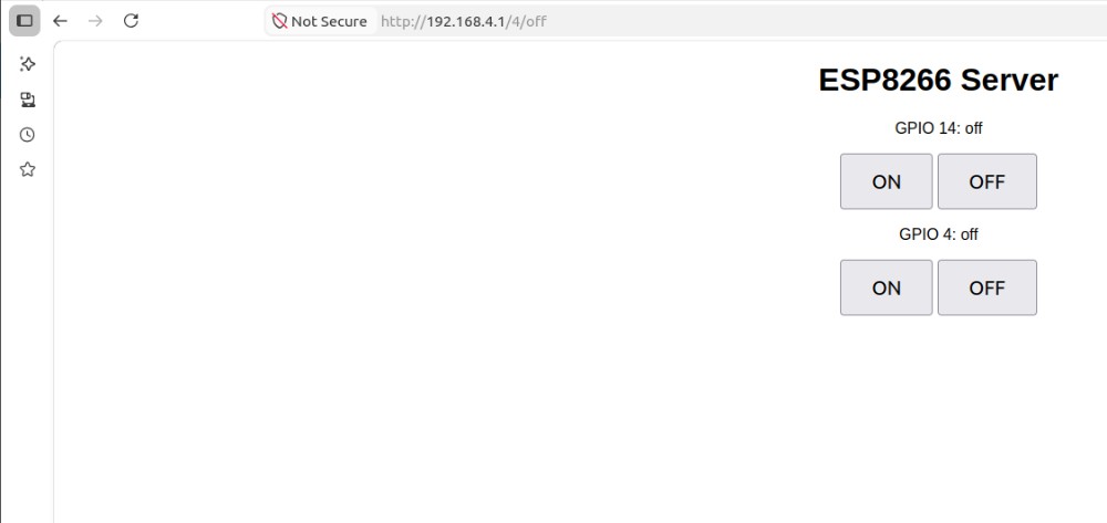
This is the same approach I used individually this week for the ESP8266 HTTP server (see below) — the "application" is just a webpage, with no install step needed on the user's side: any phone or laptop with a browser can act as the controller. We also tested hosting the page on a laptop instead, with a small Flask server bridging the browser to a board's USB-serial port — useful when the microcontroller doesn't have enough memory to run its own web server.
The downside is that anything beyond simple button clicks (continuous live data streaming) means stepping up to WebSockets, which adds real complexity on both the firmware and JavaScript sides. Making a page look good on both phone and laptop screens also took more CSS work than expected.
3. Node-RED
One group member set up Node-RED, a flow-based visual programming tool, and connected it to a board over serial using node-red-node-serialport. Instead of writing code line by line, you drag "nodes" onto a canvas and wire them together — a serial-input node feeding a function node (parsing the data) feeding a dashboard gauge node, which renders automatically on an auto-generated web dashboard. A working gauge plus an on/off toggle was running in well under fifteen minutes — the fastest result of any tool in the whole comparison for that kind of "read a sensor, show it, send a command back" use case.
The trade-off: customizing the visual appearance beyond the built-in dashboard nodes was limited, and debugging a "flow" felt less intuitive than reading a normal stack trace — errors show up as a small red triangle with limited detail.
4. Blynk / app-builder style mobile platforms
We also looked at Blynk, which lets you design a mobile-app interface (buttons, sliders, graphs) by dragging widgets onto a virtual phone screen, then connects it to a microcontroller over Wi-Fi or a cloud relay. Setting up a button and a graph widget took only a few minutes — no separate coding of the interface at all, just assigning each widget a "virtual pin" the firmware reads or writes.
This was the fastest way to get a phone (not just a laptop) controlling a board, with no app-store deployment needed. The trade-off is depending on a third-party cloud relay (or running a local server yourself), plus free-tier limits on widgets and update rate — we actually hit the update-rate limit ourselves and had to throttle our data.
5. Processing Processing (the Java-based creative-coding environment, closely related to Arduino's own IDE heritage) was tried as a middle ground between "real" GUI programming and quick visual sketches. It's particularly strong for anything involving live graphical visualization of sensor data — drawing shapes, graphs, or animations that react to incoming serial data is very natural in Processing, arguably more natural than in Tkinter. It felt less suited, though, to building "normal" application UI elements like text fields, dropdowns, or settings panels, where a toolkit like PyQt or a web page is more appropriate.
Comparison Table
| Tool | Setup time | Visual polish | Platform | Best for | Main drawback |
|---|---|---|---|---|---|
| Tkinter (Python) | Very fast | Low | Desktop only | Quick prototypes, simple controls | Dated look, limited widgets |
| PyQt / PySide (Python) | Medium | High | Desktop only | Polished desktop apps, custom dashboards | Steeper learning curve, licensing to check |
| HTML/JS (served from board or PC) | Fast–Medium | Medium–High (depends on CSS) | Any browser, any device | Cross-platform control with zero install | WebSockets needed for live/streaming data |
| Node-RED | Fast | Medium | Desktop/server, browser dashboard | Fast dashboards without much coding | Harder to debug flows, less custom styling |
| Blynk | Very fast | High (mobile-native widgets) | Mobile (iOS/Android) | Quick phone control apps | Cloud dependency, free-tier limits |
| Processing | Fast | Medium–High for visuals | Desktop only | Live data visualization/graphics | Less natural for standard UI forms |
What I Learned From This Comparison
Working through this comparison as a group made it clear that there is no single "best" tool for interface and application programming — the right choice depends heavily on what you're optimizing for. If I just need a quick desktop button to flip a GPIO pin while debugging, Tkinter is hard to beat for speed. If I want something that looks genuinely professional and might grow into a "real" desktop application, PyQt is worth the steeper learning curve. If I want anyone to be able to control my board from their own phone with literally zero setup, a web page served directly from the microcontroller (the approach I used individually this week with the ESP8266, see below) is extremely attractive, precisely because it needs no app installed and no cloud account. If the priority is visualizing data as graphs or animations reacting live to sensor input, Processing's drawing-first approach is more natural than fighting a GUI toolkit's layout system. And if speed of building a working dashboard matters more than ultimate flexibility, the flow-based approach of Node-RED or the builder-style approach of Blynk can get something usable on screen faster than writing equivalent code by hand — at the cost of being somewhat locked into how that particular tool wants you to think.
The biggest overall takeaway: before picking a tool for an interface project, it's worth asking a few quick questions first — does this need to run on a phone or a desktop? Does it need to work offline, or is a cloud/internet dependency acceptable? Is the priority visual polish, development speed, or live data visualization? Answering these up front would have saved some of us time we instead spent discovering a tool's limitations the hard way, mid-project.
Hero shot
Overview
In Week 11, I worked on networking and communication between devices. The goal was not just to connect components, but to understand how devices actually exchange data and how this data moves inside a system.
At the beginning, I thought communication is simple — just connect wires and it works. But in practice, I realized that every protocol has its own rules, timing, and logic. If even one small thing is wrong, the whole system stops working.
During this week, I worked with three protocols, and — importantly — with three different microcontroller platforms, one for each protocol:
| Protocol | Microcontroller(s) used | Role |
|---|---|---|
| UART | 2× Arduino Uno (ATmega328P) | Board 1 = sender, Board 2 = receiver |
| I2C | Custom-built ESP8266-based board (ESP-12E module) — the board I designed in Week 06 | I2C master, driving an external I2C LCD |
| HTTP (Wi-Fi) | Standalone ESP8266 (ESP-12E) module wired on breadboard | Wi-Fi Access Point + HTTP web server |
I deliberately used different boards for each protocol so I could compare not only the protocols themselves but also how each microcontroller platform handles communication differently — the plain ATmega328P on the Arduino Uno has simple hardware UART, while the ESP8266 has both I2C support and a full Wi-Fi/TCP stack built in.
Each one showed a different level of communication, from simple direct connection to full wireless control.
1. Understanding the Idea of Communication
Before building anything, I tried to understand what "communication" really means in electronics.
When two devices communicate:
- One device sends data
- The other receives it
- Both must understand the format
If they don't follow the same rules, communication fails.
For example:
- Wrong speed → data becomes garbage
- Wrong wiring → no signal
- Missing power → nothing works
This helped me understand that communication is not just wires — it is a system of rules.
2. UART Communication (Two Arduino Uno Boards)
Hardware Used
- Board 1 — Arduino Uno (ATmega328P) → programmed as the sender
- Board 2 — Arduino Uno (ATmega328P) → programmed as the receiver
Both boards are standard Arduino Uno boards based on the ATmega328P microcontroller, each connected to the laptop over its own USB cable so that both Serial Monitor windows could be observed at the same time during testing.
What I Wanted to Do
I wanted to send a simple message from one board to another and check if it arrives correctly — the simplest possible test of "can two separate microcontrollers exchange data at all" before moving on to anything more complex. The goal was specifically a two-way confirmation: not just that Board 1 sends something, but that I could actually see, in Board 2's own Serial Monitor, proof that the exact message had arrived intact.
What I Did (Real Process)
First, I took two Arduino Uno boards.
Then I connected them:
- TX of first board → RX of second
- RX of first board → TX of second
- GND → GND
At first, I connected TX to TX by mistake, and nothing worked. This helped me understand that communication must be crossed.
After wiring, I wrote two programs — one was uploaded to Board 1 (sender), and the other was uploaded to Board 2 (receiver). It's important to keep track of which sketch goes to which physical board, since uploading the wrong sketch to the wrong board (e.g. two senders, or two receivers) means nothing will ever be exchanged.
The sender sends the word "Hello" every second.
The receiver listens continuously and waits for data.
When data arrives, it reads it and prints it.
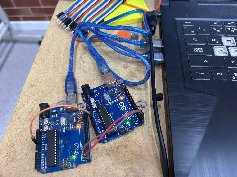
I make: two Arduino Uno boards side by side, each on its own USB cable so both Serial Monitors could be watched at once. The crossed TX/RX/GND jumper wires run between them, with the onboard TX/RX LEDs lit on the right-hand board confirming data is moving. The extra wires visible in the frame are leftovers from earlier wiring attempts before settling on the correct crossed configuration.
What Actually Happens
Inside the system:
- Sender converts text into signals
- Signals go through TX wire
- Receiver reads signals from RX
- Converts them back into text
- Receiver prints the result to its own Serial Monitor, confirming the round trip
So it's like translating between digital signals and human-readable text, with each board only ever seeing its own side of that translation.
Code
// =========================================
// UART SENDER  →  uploaded to BOARD 1 (Arduino Uno #1)
// This board's TX pin (pin 1 / D1) is wired to Board 2's RX pin
// =========================================
void setup() {
  Serial.begin(9600);   // baud rate MUST match the receiver exactly, otherwise data turns to garbage
}

void loop() {
  Serial.println("Hello");  // send the word "Hello" out over TX every second
  delay(1000);               // 1 second pause between messages, gives the receiver time to print before the next one arrives
}
// =========================================
// UART RECEIVER  →  uploaded to BOARD 2 (Arduino Uno #2)
// This board's RX pin (pin 0 / D0) is wired to Board 1's TX pin
// =========================================
void setup() {
  Serial.begin(9600);   // baud rate must match BOARD 1's sender exactly (9600 here)
}

void loop() {
  if (Serial.available()) {           // check if any new bytes have arrived on RX
    String message = Serial.readString();   // read the incoming bytes into a String
    Serial.println("Received: " + message); // print it back out to this board's own Serial Monitor for confirmation
  }
}
What I Learned
- Communication needs correct wiring
- Both devices must use same speed
- Even simple systems can fail easily
- A wiring mistake produces total silence, with no error message at all
- UART has no built-in way to confirm a message arrived — that's on you to add
UART helped me understand the basics of communication, and how much the physical wiring matters here compared to the other two protocols.
3. I2C Communication (LCD Display)
Hardware Used
- Custom ESP8266 development board (built around the ESP-12E module) — this is the board I designed and milled during Week 06 — Electronics Design, where the full schematic, component placement, and PCB layout are documented. The original board schematic (showing the ESP-12E module, decoupling capacitors, pull-up resistors, and the SPI/UART/GPIO headers used here) can be found in the Week 06 page, in the section "Schematic Editor — Drawing the Circuit", with the final routed board shown under "Final PCB". (Week 06 documentation)
- I2C LCD module (16x2, with PCF8574 I2C backpack) acting as the I2C slave device
The ESP-12E module on my custom board acted as the I2C master, generating the clock signal and addressing the LCD's I2C backpack directly over just two wires (SDA/SCL), instead of the many parallel data pins a standard HD44780 LCD would normally require.
What I Wanted to Do
Display text on an LCD using only two wires, instead of the many parallel data pins a standard HD44780 character LCD normally needs — a good test of whether I understood I2C addressing well enough to actually drive a real peripheral, not just blink an LED.
What I Did (Real Process)
I connected the LCD to my custom board using:
- SDA
- SCL
- VCC
- GND
At first, nothing appeared on the screen, even though the board itself seemed to be powering up correctly.
I checked:
- wiring
- code
- power
Then I realized:
- LCD needs correct address (I had assumed the wrong one from a generic example online)
- LCD needs stable power, since a slightly low or noisy VCC was enough to keep the backlight on but leave the text unreadable
After fixing these — running a quick I2C scanner sketch to find the real address, and tightening the VCC connection — it started working.
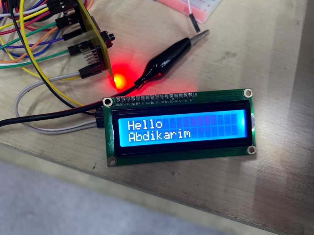
I make: the first photo is the wiring stage, taken while the LCD was still blank — colored jumper wires running from the ESP8266 board's header down to the breadboard, with the onboard LED confirming power was reaching the module. The second photo shows the working result: the LCD lit up with "Hello Abdikarim" in white text on a blue backlight, after fixing the address and power issues described below.
What Actually Happens
In I2C:
- The microcontroller sends a signal
- It includes the address of the device
- Only that device responds
- Data flows over the same two SDA/SCL wires regardless of how many devices share the bus
So unlike UART, here many devices can exist on the same wires, but only one responds at a time based on its address.
Code
// =========================================
// I2C MASTER CODE  →  uploaded to the CUSTOM ESP8266 BOARD (ESP-12E, Week 06 board)
// This board acts as the I2C MASTER, the LCD's PCF8574 backpack is the I2C SLAVE
// SDA/SCL pins come from the board's I2C header — same board documented in Week 06
// =========================================
#include <Wire.h>                  // Wire library handles the low-level I2C protocol (clock generation, addressing, ACK/NACK)
#include <LiquidCrystal_I2C.h>     // higher-level library that talks to the PCF8574 I2C-to-parallel backpack on the LCD

LiquidCrystal_I2C lcd(0x27, 16, 2);  // 0x27 = I2C address of the LCD backpack (found by I2C scanner) — WRONG address = blank screen
                                       // 16, 2 = LCD is 16 characters wide, 2 rows tall

void setup() {
  lcd.init();        // initializes the I2C bus and sends the LCD's startup command sequence
  lcd.backlight();   // turns on the LCD's backlight LED (separate from the I2C data, but needed to see the result)
  lcd.setCursor(0, 0);     // move the "cursor" to column 0, row 0 (top-left of the screen)
  lcd.print("Hello Abdikarim");   // send the text over I2C to be displayed on the LCD
}

void loop() {
  // nothing needed here — the message is written once in setup() and stays on screen
}
What I Learned
- I2C reduces wires
- Address is very important
- Power stability matters a lot
- Multiple devices can share the same SDA/SCL wires — no extra wiring needed for each new device
- Running an I2C scanner sketch first is much faster than guessing the address from a datasheet
This was more complex than UART, but more powerful — the shared-bus idea was the biggest conceptual jump from last protocol.
4. HTTP Communication (ESP8266 Wi-Fi)
Hardware Used
- Standalone ESP8266 module (ESP-12E), wired on a breadboard for this test, separate from the custom Week 06 board — set up as a Wi-Fi Access Point + HTTP server
- 2× LEDs with current-limiting resistors, connected to GPIO14 and GPIO4 on the breadboard
- A phone/laptop browser was used as the HTTP client, connecting over Wi-Fi to control the LEDs remotely
What I Wanted to Do
Control LEDs from my phone using Wi-Fi — no wires between the controller (my phone) and the board at all, just a webpage with ON/OFF buttons that actually switches a real GPIO pin on the ESP8266.
What I Did (Real Process)
I connected:
- 2 LEDs
- resistors
- ESP8266
Then I wrote code to:
- connect to Wi-Fi (as its own Access Point, not joining an existing router)
- create a web server listening on port 80
- show ON/OFF buttons for each GPIO pin
At first:
- Wi-Fi did not connect
- page did not load
I checked:
- SSID and password
- serial monitor (to print the board's actual IP address)
- IP address typed into the browser
After fixing mistakes — a typo in the password, and an IP address copied incorrectly from the Serial Monitor — I opened the IP in browser.
Then I pressed buttons — and LEDs turned ON/OFF, confirming the round trip from a button tap in the browser all the way to a physical GPIO pin changing state.
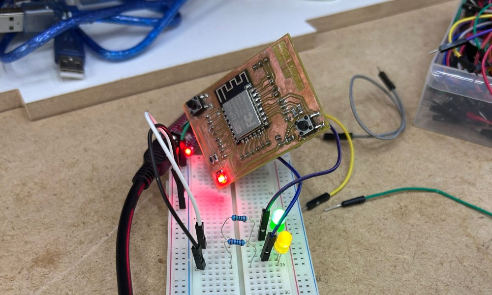
I make: the standalone ESP-12E module on its breakout PCB, propped above the breadboard holding the green and yellow LED circuits wired to GPIO14 and GPIO4. The green LED is lit here, captured right after tapping "ON" on the web page loaded in my phone's browser; the module's own status LED confirms it was actively running the Wi-Fi access point at that moment.
What Actually Happens
- Browser sends request (like
/14/on) - ESP8266 receives request
- Code checks what was requested
- Executes command (turn LED ON)
- Server sends back an updated webpage showing the new state
So now communication is not just wires — it is over network, with the board itself acting as both the network (Access Point) and the destination (web server) at the same time.
Code
// =========================================
// HTTP SERVER CODE  →  uploaded to the STANDALONE ESP8266 (ESP-12E) MODULE on the breadboard
// This board creates its OWN Wi-Fi network (Access Point) and runs a tiny web server on port 80
// Any browser that connects to this Wi-Fi and opens the board's IP address becomes the HTTP CLIENT
// =========================================
#include <ESP8266WiFi.h>

const char* ssid = "ESP8266_SERVER";   // name of the Wi-Fi network this board will broadcast
const char* password = "12345678";     // password required to join that Wi-Fi network

WiFiServer server(80);   // create a server listening on TCP port 80 (the standard HTTP port)

String header;   // will store the raw HTTP request text coming from the browser, line by line

String output5State = "off";   // tracks the current ON/OFF state of GPIO14, just for displaying on the web page
String output4State = "off";   // tracks the current ON/OFF state of GPIO4

const int output5 = 14;  // GPIO14 = D5 on the board, controls LED #1
const int output4 = 4;   // GPIO4  = D2 on the board, controls LED #2

unsigned long currentTime = millis();
unsigned long previousTime = 0;
const long timeoutTime = 2000;   // if a connected client goes quiet for 2 seconds, give up and close the connection

void setup() {
  Serial.begin(115200);   // used only to print debug info (IP address, incoming requests) to the Serial Monitor

  pinMode(output5, OUTPUT);
  pinMode(output4, OUTPUT);
  digitalWrite(output5, LOW);   // both LEDs start OFF
  digitalWrite(output4, LOW);

  WiFi.softAP(ssid, password);   // turn this ESP8266 into its own Wi-Fi Access Point (no router needed)

  Serial.println("WiFi создан!");
  Serial.print("IP адрес: ");
  Serial.println(WiFi.softAPIP());   // print the IP address that browsers must type in to reach this board (usually 192.168.4.1)

  server.begin();   // start listening for incoming HTTP connections
}

void loop() {
  WiFiClient client = server.available();   // check if a new browser/client has connected

  if (client) {
    currentTime = millis();
    previousTime = currentTime;
    Serial.println("New Client.");
    String currentLine = "";

    // keep reading from this client until it disconnects, or until it goes silent for too long (timeoutTime)
    while (client.connected() && currentTime - previousTime <= timeoutTime) {
      currentTime = millis();

      if (client.available()) {
        char c = client.read();        // read one character of the incoming HTTP request
        Serial.write(c);                // echo it to Serial Monitor for debugging
        header += c;                    // build up the full request text

        if (c == '\n') {
          // a blank line means the browser has finished sending its HTTP request headers
          if (currentLine.length() == 0) {

            // standard HTTP response headers — required before sending any HTML
            client.println("HTTP/1.1 200 OK");
            client.println("Content-type:text/html");
            client.println("Connection: close");
            client.println();

            // === decide what to do based on which URL/button was requested ===
            if (header.indexOf("GET /14/on") >= 0) {
              output5State = "on";
              digitalWrite(output5, HIGH);   // turn LED #1 ON
            } else if (header.indexOf("GET /14/off") >= 0) {
              output5State = "off";
              digitalWrite(output5, LOW);    // turn LED #1 OFF
            } else if (header.indexOf("GET /4/on") >= 0) {
              output4State = "on";
              digitalWrite(output4, HIGH);   // turn LED #2 ON
            } else if (header.indexOf("GET /4/off") >= 0) {
              output4State = "off";
              digitalWrite(output4, LOW);    // turn LED #2 OFF
            }

            // === send back the actual webpage with buttons, shown in the browser ===
            client.println("<!DOCTYPE html><html>");
            client.println("<head><meta name=\"viewport\" content=\"width=device-width, initial-scale=1\">");
            client.println("<style>body{text-align:center;font-family:Arial;} .button{padding:15px 30px;font-size:20px;} </style></head>");
            client.println("<body><h1>ESP8266 Server</h1>");

            client.println("<p>GPIO 14: " + output5State + "</p>");
            client.println("<a href=\"/14/on\"><button class=\"button\">ON</button></a>");
            client.println("<a href=\"/14/off\"><button class=\"button\">OFF</button></a>");

            client.println("<p>GPIO 4: " + output4State + "</p>");
            client.println("<a href=\"/4/on\"><button class=\"button\">ON</button></a>");
            client.println("<a href=\"/4/off\"><button class=\"button\">OFF</button></a>");

            client.println("</body></html>");
            client.println();

            break;   // response sent, exit the inner while-loop
          } else {
            currentLine = "";   // reset for the next line of the incoming request
          }
        } else if (c != '\r') {
          currentLine += c;   // build up the current line character by character
        }
      }
    }

    header = "";        // clear the request buffer for the next client
    client.stop();       // close this connection
    Serial.println("Client disconnected.");
  }
}
What I Learned
- Devices can be controlled remotely
- Communication can happen over internet
- This is the base of IoT
- The ESP8266 acting as its own Access Point means no router is needed at all — works anywhere
- The simple server code has no authentication, so anyone on the Wi-Fi can control the LEDs — fine for a class demo, not for a real product
This felt like the most "complete" result of the three protocols — pressing a button on my own phone and watching a real LED respond, with no wires at all.
Comparison (My Understanding)
Looking back across all three protocols now that I've actually wired and coded each one with a different microcontroller, the simplest summary is: UART → easiest, but limited, I2C → more flexible, HTTP → most powerful but complex. But there's more nuance to that than just three bullet points once you actually consider how each one behaves in practice.
UART is genuinely the easiest to understand conceptually — two wires, no addressing, no clock signal to worry about, just "send this, receive that" — but that simplicity is also exactly its limitation: it only ever connects two devices to each other directly, there's no way to add a third device onto the same pair of wires, and there's no built-in way to confirm a message actually arrived unless you design that confirmation yourself. I2C solves the "only two devices" problem completely by introducing addressing on a shared two-wire bus, which is a real step up in flexibility — multiple sensors, displays, and other peripherals can coexist on the exact same SDA/SCL lines — but that flexibility comes at the cost of needing to know, find, or scan for each device's address, and of dealing with a slightly more involved electrical setup (pull-up resistors, more careful attention to bus speed). HTTP over Wi-Fi is the most capable of the three by a wide margin — it allows full wireless control from essentially any device with a browser, with no dedicated wiring between the controller and the board at all — but it's also the protocol with by far the largest number of moving parts that can go wrong: network names, passwords, IP addresses, the structure of the HTTP request/response itself, and (if you go further than I did this week) security and multi-client handling.
If I had to map these three onto a single "complexity vs. capability" curve, UART would sit at the bottom-left (low complexity, low capability), I2C somewhere in the middle (moderate complexity, meaningfully more capable thanks to addressing and bus-sharing), and HTTP/Wi-Fi at the top-right (highest complexity, but capability that genuinely unlocks things the other two simply cannot do, like controlling a device from across a room with a phone someone already owns). None of the three protocols is strictly "better" than the others in an absolute sense — which one is the right choice depends entirely on the actual requirement: a quick debug link between two boards sitting next to each other on a bench calls for UART, a sensor-plus-display setup on a single PCB calls for I2C, and anything that needs to be controlled remotely or wirelessly calls for HTTP (or another wireless protocol built on top of Wi-Fi/Bluetooth).
Reflection
This week changed how I understand electronics, and more specifically, how I understand what it actually means for two pieces of hardware to "talk" to each other.
Before: I thought components just work together — you connect a sensor or a display to a microcontroller, write some code, and it works, more or less by default, the way plugging in a USB mouse just works on a laptop.
Now: I understand they communicate using rules and signals, and that every single one of those rules has to be satisfied at the same time for anything to work at all — the correct wiring, the correct timing (baud rate, clock speed), the correct addressing where addressing is relevant, and the correct logical structure in the code on both ends of the conversation. None of these "just happen" — they're all decisions, made either by the protocol's design or by me as the person wiring and coding the system, and getting any single one of them wrong is enough to break the whole link, even when everything else about the setup is correct.
The biggest lesson of the week, repeated across all three protocols in slightly different forms: even a small mistake → system fails completely, often with very little indication of why. A crossed UART wire produces total silence. A wrong I2C address produces a blank screen. A mistyped Wi-Fi password produces a page that simply never loads. None of these failure modes come with a helpful error message pointing at the actual problem — they just don't work, and figuring out why they don't work is the actual skill being practiced this week, far more than memorizing protocol details.
Debugging step by step is the most important skill I'm taking away from this week, more than any specific protocol's syntax or library. Concretely, that meant: checking power first (is the board even getting voltage?), then checking the physical connections one wire at a time (am I certain TX is going to RX and not TX to TX?), then checking the software configuration (does the baud rate, address, or SSID actually match on both ends?), and only after all of that, looking at the actual logic of the code itself. Working through three different protocols and three different boards in the same week made this process feel less like protocol-specific trivia and more like a general debugging method I can carry forward into any future networking or communication problem, regardless of which specific protocol or microcontroller is involved.
I also noticed, somewhat unexpectedly, that the three protocols built on each other conceptually even though I tackled them somewhat in parallel rather than in a strict order — understanding UART's simple "just two wires, no addressing" model made I2C's addressing concept land much more clearly by contrast, and understanding I2C's master/slave request-response pattern made HTTP's client/server request-response pattern feel familiar rather than entirely new, even though HTTP operates over a completely different physical medium (Wi-Fi instead of direct wires).
Conclusion
This week helped me understand how devices talk to each other — not as an abstract networking concept, but as something I could physically wire up, watch fail in a specific and explainable way, fix, and then watch succeed, three separate times with three different protocols and three different microcontrollers.
Now I can: - send data between two independent boards over a simple wired link (UART), and understand exactly why crossing the wires and matching the baud rate both matter - receive and display data on a shared two-wire bus with proper addressing (I2C), and know to scan for a device's address rather than assume it - control devices remotely over Wi-Fi from a phone or laptop browser with no dedicated wiring at all (HTTP), and understand the request/response flow happening underneath the buttons on a webpage
Beyond the three protocols themselves, this week also reinforced a working method I expect to reuse constantly going forward: when a communication link doesn't work, check power, then check wiring, then check configuration (speed/address/credentials), and only then suspect the actual logic of the code. This is very important for my final project and future work, since almost any embedded project beyond the simplest standalone gadget eventually needs some device to talk to some other device — whether that's a sensor reporting data to a microcontroller, a microcontroller reporting data to a phone, or several boards on a shared project coordinating with each other — and this week gave me hands-on, debugged-from-scratch experience with the three protocols most likely to come up in exactly that kind of situation.