Week 13 — Molding and Casting
Assignments
Group Assignment
- Review the safety data sheets for each molding and casting material
- Make and compare test casts with each material
Individual Assignment
- Design a mold around the process you'll be using
- Produce it with a smooth surface finish that does not show the production process
- Use it to cast parts
Learning Outcomes
- Design appropriate objects within the limitations of your process
- Demonstrate workflows used in mold design, construction and casting
Individual Project: Silicone Soft Gripper
For this week's individual assignment, I decided to design and fabricate a soft pneumatic gripper made entirely from two-part silicone rubber. The concept of a soft gripper comes from the field of soft robotics — a branch of robotics that focuses on building machines from flexible, compliant materials rather than rigid metal or plastic. This approach is especially valuable in situations where a robot needs to handle fragile, irregular, or delicate objects without damaging them.
Traditional rigid grippers use motors and metal fingers, which require precise control to avoid crushing what they hold. A soft pneumatic gripper works completely differently: it uses air pressure to deform its own body. When you inflate the internal channels inside the fingers, the asymmetric wall structure causes the fingers to curl inward, wrapping naturally around any object in their path. No motors, no sensors — just geometry and pressure.
I chose this project because it sits at the intersection of molding and casting, mechanical design, and robotics — and because it's a genuine challenge that requires thinking carefully about every step of the fabrication process. A soft gripper is not a decorative object; it has to work. That makes the design decisions much more meaningful.
Background: What is a Soft Pneumatic Gripper?
A soft pneumatic gripper typically consists of two or more flexible fingers, each containing an internal network of air channels. When pressurized air is injected through an inlet, the channels expand. Because one side of the finger is thicker (the outer wall) than the other (the inner wall), the expansion is uneven — the thin side stretches more, and the finger bends toward the thick side. This is the same principle behind a PneuNet actuator, which is one of the most well-known designs in soft robotics research, originally developed at Harvard University's Whitesides Research Group.
The key advantage of this design is that it requires no electronic control for basic gripping — you simply pump air in and the fingers close. Release the pressure, and the silicone springs back to its original shape due to its natural elasticity. This makes it mechanically simple, lightweight, and safe to use around humans or delicate objects. Soft grippers like this are increasingly used in food handling, medical robotics, and human-robot interaction research precisely because they cannot injure people the way a rigid gripper can.
The challenge, of course, is in the fabrication. Silicone is a difficult material to work with precisely. The internal channels must be thin-walled and airtight. The two halves of the gripper must bond together perfectly. Any small leak or misalignment and the whole thing fails to actuate. This week was my introduction to that challenge — and a valuable one.
Materials & Safety
Two-Part Silicone (Part A + Part B)
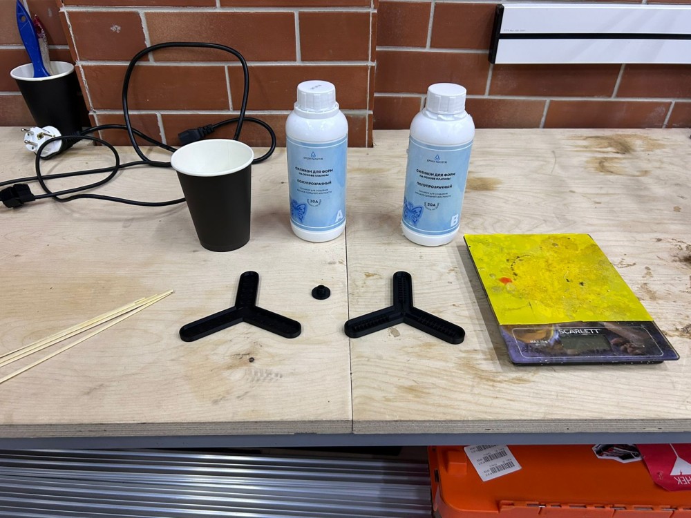
The material I used for casting is a two-component addition-cure silicone rubber. This type of silicone comes in two separate parts — commonly called Part A and Part B — which are chemically inert on their own but react and crosslink when combined. Unlike condensation-cure silicones (which release a byproduct during curing and can shrink slightly), addition-cure silicones cure with almost zero shrinkage, which is critical for dimensional accuracy in mold work.
The mixing ratio for my silicone was 1:1 by weight, meaning equal parts A and B. Some silicones use ratios like 10:1 or 100:10 by weight — always check the technical data sheet for the specific product you are using, because getting this ratio wrong will result in a part that is either permanently tacky, too soft, or simply doesn't cure at all.
Properties of cured silicone relevant to this project: - Highly elastic — can stretch several times its original length and return to shape without permanent deformation - Chemically inert — resistant to water, many solvents, and temperature extremes from -60°C to over 200°C - Biocompatible — safe for skin contact in most medical-grade formulations - Translucent to opaque depending on pigment additives - Shore A hardness typically in the range of 10–40 for soft robotics applications — I used a softer formulation to allow the channels to deform at lower pressures
Safety Data Sheet (SDS) summary:
Before starting any casting work, I reviewed the SDS documents for both Part A and Part B. Key findings:
- Hazard classification: Both components are classified as non-hazardous under standard conditions. They are not flammable, not corrosive, and not acutely toxic at typical exposure levels.
- Skin and eye contact: Prolonged or repeated skin contact with uncured silicone may cause mild irritation in sensitive individuals. Always wear nitrile gloves and safety glasses when handling uncured material. If skin contact occurs, wash thoroughly with soap and water. Avoid touching eyes.
- Inhalation: Uncured silicone has very low vapour pressure at room temperature, meaning it does not readily evaporate into the air. Working in a normally ventilated space is sufficient for occasional use — no respirator is required under standard Fab Lab conditions.
- Ingestion: Do not ingest. While cured silicone is considered food-safe in many formulations, uncured components should be treated as industrial chemical substances and kept away from food and drink.
- Inhibition warning — critical: Addition-cure silicones are extremely sensitive to inhibition by sulfur-containing compounds. Materials that commonly cause inhibition include: plasticine/oil-based clay (contains sulfur), latex gloves (contains sulfur), tin-cure silicone residue, and some paints and coatings. Even trace contamination from these materials — a tool that touched plasticine, for example — can prevent the silicone from curing, leaving a permanently sticky, uncured surface. To avoid inhibition: use only clean PLA, ABS, or acrylic molds; use only nitrile or vinyl gloves; use clean, dedicated mixing tools; and never reuse containers that held other silicone products.
- Disposal: Fully cured silicone is chemically inert and can generally be disposed of in regular solid waste. Mixed but uncured silicone should be allowed to cure completely before disposal. Do not pour uncured mixed silicone down drains.
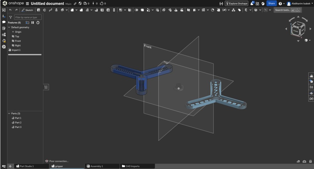
Mold Design in Onshape
I designed the mold using Onshape, a fully browser-based parametric CAD platform developed by the founders of SolidWorks. Onshape requires no local installation, saves automatically to the cloud with full version history, and supports real-time multi-user collaboration — making it ideal for distributed Fab Academy work. For mold design specifically, its parametric feature tree makes it straightforward to adjust a wall thickness or channel dimension and have the entire model regenerate automatically without rebuilding from scratch.
Design Philosophy
Designing a mold for a soft gripper finger is quite different from designing the gripper itself. You are not designing the object — you are designing the negative space that will form the object. Every surface inside the mold becomes a surface of the final silicone part. Every edge, corner, texture, and even fingerprint on the mold interior will be faithfully reproduced in the cast, because silicone is an extraordinary surface replicator.
This means you have to think in reverse: the walls that create the internal air channels of the gripper are actually positive cores protruding into the mold cavity — solid features that the silicone flows around and then releases from during demolding. Getting this geometry right requires thinking carefully about how the liquid silicone will flow, where air might get trapped, and how the cured part will come out without tearing or locking.
Mold Structure
I designed the mold as two separate halves — a top half and a bottom half — that fit together to define the complete internal geometry of one gripper finger. This two-part approach is standard practice for any part that cannot be released from a single open-face mold due to undercuts, enclosed channels, or complex geometry. The gripper finger, with its internal pneumatic channels, clearly requires this approach.
Key design decisions I made and the reasoning behind each:
Draft angles: All vertical walls in the mold cavity have a slight outward taper of 1–2 degrees. This is called a draft angle, and it is one of the most fundamental rules of mold design. Without draft angles, the silicone part grips the mold walls as it tries to be pulled out, creating enormous friction — the part either tears or the mold deforms. With even a 1-degree draft, the contact area decreases as you begin to pull the part out, making demolding much easier and safer.
Alignment pins and sockets: The two mold halves need to register precisely so the internal channels are symmetric and the parting line — the seam where the two halves meet — is clean and flush. I added two cylindrical alignment pins on one half and corresponding sockets on the other. This ensures the molds snap together in exactly the right position and cannot shift during casting or cure.
Pour spout and vent: At the top of the mold I added a funnel-shaped pour channel through which the mixed silicone is poured. At the highest point of the internal cavity I added a small vent hole — as the silicone rises and fills the mold from below, air needs somewhere to escape. Without a properly placed vent, trapped air creates bubbles and voids inside the part, which break up the internal channels and create weak spots in the walls.
Smooth interior surfaces: In parametric CAD, surfaces look perfectly smooth on screen. But FDM 3D printing introduces layer lines — horizontal ridges every 0.1–0.2 mm — that transfer directly onto the silicone surface if not addressed in post-processing. I designed the mold with this in mind, choosing surfaces that are accessible for sanding with flat and folded sandpaper, and avoiding deep narrow recesses where finishing tools cannot reach.
Internal channel geometry: The pneumatic channels inside the gripper finger follow a PneuNet-inspired pattern — a series of connected rectangular chambers separated by thin walls on the inner bending face. The ratio between wall thickness on the outer face versus the inner face is what determines the bending direction and magnitude. I modeled these channels as solid cores in the mold, checking each feature to confirm it could be cleanly demolded — no hidden undercuts, no geometry that would lock the silicone permanently in place.
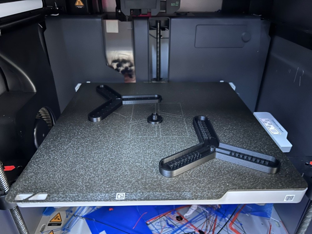
Mold Production — 3D Printing in PLA
Once the mold design was complete and verified in Onshape, I exported both halves as STL files and printed them on an FDM 3D printer using PLA filament.
Why FDM Printing for the Mold?
FDM printing was the right choice for this mold for several reasons. The gripper finger geometry includes internal channel structures that would be extremely difficult or impossible to machine with a CNC mill — the internal cores and overhangs require either 3D printing or multi-part mold designs with complex parting lines. FDM printing allows complete geometric freedom for this type of organic, channel-heavy geometry. It is also fast and inexpensive for prototype molds, allowing me to iterate quickly if the design needs changes.
The primary limitation of FDM for molds is surface finish — the layer lines require post-processing. But for silicone molds, this is manageable through sanding, which I describe below.
Print Settings
Print settings matter significantly when producing molds. My choices:
- Layer height: 0.1 mm — fine detail mode, used to minimize the height of layer ridges on the mold interior surfaces. At 0.2 mm standard layer height, the ridges are visible and tactile on the final silicone part.
- Infill: 50% grid pattern — the mold needs to be structurally rigid. If the mold walls flex during casting, the internal geometry shifts and the part comes out distorted.
- Wall perimeters: 4 — thick, solid outer walls ensure the mold surface is non-porous. FDM parts with thin wall counts can have micro-gaps between perimeters where liquid silicone seeps in during casting.
- Print orientation: no supports in cavity — I oriented both mold halves so that no support structures were needed inside the mold cavity. Support material leaves rough, uneven surfaces that are nearly impossible to sand cleanly, and any roughness transfers to the silicone.
Surface Finishing — Sanding
After printing, the mold interior surfaces still showed visible layer lines from the FDM process. Silicone will replicate these lines precisely, so removing them completely before casting is essential for a clean part surface.
I sanded the interior surfaces progressively through the following grit sequence:
- 120 grit — aggressive material removal to take down the peaks of layer ridges and remove any print artifacts like strings or blobs
- 220 grit — smoothing the scratches left by 120 grit, surface begins to feel uniform
- 400 grit — further refinement, visible layer lines are gone, surface starts to feel smooth to the touch
- 800 grit — near-optical smoothness, no layer lines remaining, silicone will release cleanly
For the deep and narrow areas around the channel cores, I used small pieces of sandpaper folded around a wooden stick and small round files. This stage requires patience — trying to rush it results in inconsistent surface quality that shows up in the final part.
Mold Release Agent
After sanding, I applied mold release spray to all interior surfaces of both mold halves. Mold release creates a thin physical barrier between the silicone and the PLA, preventing adhesion. Without release agent, silicone can form a permanent chemical and mechanical bond to the mold, making demolding impossible without destroying one or both.
I applied two thin coats of release spray, allowing each coat to dry fully (about 5 minutes) before applying the next. It is important to coat every surface thoroughly — any missed patch will stick.
Casting Process — Step by Step
With the molds prepared, sanded, and released, I was ready to mix and cast. It is important to have everything prepared before mixing — once Part A and Part B are combined, the pot life clock starts and there is no pausing.
Step 1: Preparation
Before mixing, I assembled the two mold halves and secured them together with clamps. I verified that the alignment pins were fully seated and there were no visible gaps at the parting line. I also confirmed the pour spout was accessible and the vent hole was open. I laid out the digital scale, clean mixing cup, wooden stick, and both silicone components within easy reach.
Step 2: Mixing the Silicone (50/50 by Weight)
I placed the mixing cup on the scale and tared to zero. I poured Part A to the target weight, recorded the number, then tared the scale again and added an exactly equal weight of Part B. Achieving a precise 50/50 ratio by weight is non-negotiable — even a 5–10% deviation can noticeably affect cure time, final hardness, and mechanical properties.
Mixing was performed with slow, deliberate strokes for 3–4 minutes. I used a folding and scraping technique rather than vigorous stirring — aggressive mixing introduces a large amount of air bubbles into the silicone that can become trapped in the final part. I scraped the sides and bottom of the cup repeatedly to ensure no unmixed Part A or Part B remained in pockets at the edges.
Part A and Part B are typically slightly different in visual appearance — one may be slightly more opaque or tinted — which makes it possible to visually confirm when the blend is uniform. I mixed until no streaks or regions of different colour were visible.
⚠️ Critical note: Incomplete mixing is one of the most common causes of failed silicone casts. Any unmixed material will remain liquid or tacky in the final part, creating weak spots, leaky regions, and potential channel blockages. Always take the full time to mix thoroughly.
Step 3: Pouring into the Mold
With the silicone fully mixed, I poured it slowly into the pour spout of the assembled mold. I poured from a height of about 15–20 cm in a thin, steady stream — this thin-stream technique allows small bubbles to pop as the silicone falls and also reduces the turbulence as it enters the cavity. I poured into one consistent point and let the silicone self-level and fill the cavity from below, naturally pushing air upward and out through the vent hole.
I watched carefully for the silicone to appear at the vent hole, which confirmed the cavity was fully filled. I poured a slight excess to ensure the cavity was completely filled without voids near the top surface, then stopped and gently cleaned any overflow from around the pour spout before it could cure and interfere with demolding.
Step 4: Initial Cure — Refrigerator (30 minutes)
Immediately after pouring, I placed the fully filled mold into the refrigerator for 30 minutes. This step might seem counterintuitive, but it serves an important purpose. Cold temperatures significantly slow down the crosslinking reaction in addition-cure silicones, effectively extending the pot life of the material inside the mold. This gives any remaining air bubbles more time to rise through the liquid silicone and escape before the material begins to gel and trap them permanently.
At room temperature (around 22–25°C), my silicone would begin to gel within approximately 20–30 minutes. By cooling the mold to refrigerator temperature (~5°C), I extended this window significantly, giving the silicone more time to fully wet out the mold surfaces, flow into fine details, and release trapped bubbles.
Step 5: Heat Cure at 50°C
After removing the mold from the refrigerator, I transferred it to a conventional oven preheated to 50°C for the main cure and post-cure phase. Applying moderate heat accelerates the crosslinking reaction dramatically — what might take 24 hours at room temperature can be achieved in 1–2 hours at 50°C. Elevated temperature curing also improves the final material properties: higher crosslink density results in better elasticity, higher tear strength, and improved resistance to mechanical fatigue over repeated actuation cycles.
50°C was chosen specifically because it is safely below the glass transition temperature of PLA (around 55–60°C under load). Exceeding that temperature could cause the mold to soften and deform, which would distort the internal geometry of the part. I monitored the oven temperature with a separate probe thermometer throughout the cure to ensure it remained stable.
I left the mold in the oven until the silicone was fully cured — confirmed by pressing gently on the exposed silicone at the pour spout and finding it completely firm and non-tacky.
Step 6: Demolding
After the cure cycle was complete, I removed the mold from the oven and allowed it to cool for a few minutes before demolding. I removed the clamps and carefully began separating the two mold halves by prying gently at the parting line with a thin flat tool, working progressively around the entire perimeter rather than forcing one corner. Gradual, even pressure is essential — sudden force can tear thin walls in the silicone part.
The mold release agent performed well — both halves separated from the silicone cleanly without adhesion. The silicone part remained intact inside one half, and I gently peeled it away from the remaining surface with my fingers.
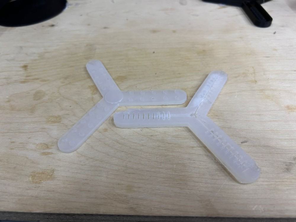
The demolded silicone half had excellent surface quality. No layer lines were transferred from the mold walls, the internal channel structure was clearly visible through the translucent silicone, and the parting line on the silicone part was clean and flush.
Assembly — Bonding the Two Halves
Each casting produces one half of the gripper finger — either the top or bottom section, depending on which mold half it came from. To create a functional pneumatic actuator, the two halves must be bonded together to completely enclose the internal air channels and form a sealed pneumatic circuit.
Bonding Method: Silicone-to-Silicone Adhesive
The most reliable method for joining two cured silicone parts is to use fresh, uncured silicone as the bonding agent. Silicone bonds best to itself — the uncured material chemically crosslinks with the already-cured surfaces on both sides of the joint, creating a bond that approaches the strength of the bulk silicone. This is superior to using commercial adhesives, most of which have poor adhesion to silicone surfaces.
The process I followed:
- Cleaned both mating faces with isopropyl alcohol to remove any dust, release agent residue, or contamination that could prevent bonding
- Mixed a small batch of fresh silicone (Part A + Part B, 1:1 by weight) in a clean cup
- Using a fine brush, applied a thin, even layer of uncured silicone to the mating face of one half — covering the entire surface uniformly without excess
- Carefully aligned the two halves, using the channel geometry as a visual reference for alignment
- Pressed the two faces together firmly by hand, then applied clamps around the perimeter to maintain even contact pressure during the cure
- Left the assembly clamped at room temperature for the full cure time
The most critical aspect of this step is achieving complete contact without excess adhesive entering the channels. Too little silicone adhesive and the bond will have gaps — even a 0.1 mm gap in the joint line is enough to allow significant air leakage under pneumatic pressure. Too much adhesive and the excess squeezes inward into the channel openings, reducing or blocking the cross-section that air needs to flow through.
I inspected the bond line from all sides after clamping, using a bright light to check for any visible gaps or areas of incomplete contact. The joint appeared clean and flush.
Testing — Pneumatic Actuation
Once the bonding cure was complete and the clamps removed, I was ready to test whether the gripper would actuate. I connected a 20 ml medical syringe to the air inlet port of the gripper using a short length of flexible silicone tubing and a push-fit connector sized to match the inlet diameter. The syringe allows me to manually inject a measured volume of air and observe the gripper's response.
Test Procedure
- Connected the syringe to the inlet with a tight, secure seal — any leakage at the connection itself would invalidate the test
- Held the gripper in a free position where the fingers could bend without obstruction
- Slowly and steadily depressed the syringe plunger to inject air into the internal channels
- Observed the gripper carefully for any visible bending, swelling, or actuation in the finger segments
- Progressively increased pressure by depressing the syringe further, up to the limit of what I could generate by hand
Result
On this first test, the gripper did not actuate as expected. When injecting air, I could feel clear resistance building in the syringe — suggesting the channels were at least partially intact and some pressure was building inside. However, no visible bending or curling of the finger occurred. Under higher applied force, I noticed what appeared to be a very faint, slow leakage of air at a section of the bond line, visible as a slight deformation of the joint when held up to a light.
This result, while disappointing, is genuinely expected for a first prototype of a soft pneumatic actuator. The failure is informative — it gives me specific hypotheses to investigate and test in the next iteration.
Failure Analysis — Possible Causes
1. Air leakage at the bond joint (most likely) If the bond between the two halves is not perfectly airtight across its entire surface, pressure bleeds out faster than it builds up inside the channels. Even a 0.5 mm unsealed patch in the joint is sufficient to prevent actuation under hand-syringe pressure levels. The faint leakage I observed at the bond line supports this hypothesis. The fix: increase the width of the bonding face, apply greater clamping pressure during cure, and consider post-applying additional silicone around the exterior of the bond line as a sealant layer.
2. Blocked internal channels If excess silicone adhesive was squeezed into the channel openings during assembly, it could partially or fully block the air path between chambers. If the chambers cannot fill with air, there is no pressure differential to drive bending. The fix: inspect the channels by injecting coloured water or using a fine wire to probe for blockages, and redesign the bonding face with a channel-protection lip that prevents adhesive from entering.
3. Channel wall thickness too high If the thin inner walls of the PneuNet chambers are too thick relative to the outer walls, the silicone may be too stiff to deform meaningfully at the pressure levels achievable with a hand syringe. The bending behavior depends on a significant stiffness asymmetry between the inner and outer walls. The fix: reduce inner wall thickness by 20–30% in the next mold revision and verify the asymmetry ratio against published PneuNet design parameters.
4. Insufficient pressure from manual syringe Many published soft gripper designs require sustained pressures of 30–80 kPa (0.3–0.8 bar) to achieve full actuation. A 20 ml syringe operated by hand can generate roughly 10–20 kPa at best. If the gripper requires more than this to overcome material stiffness, it simply won't move with a syringe. The fix: test with a bicycle pump or small air compressor connected through a pressure gauge and needle valve, allowing controlled pressure up to 100+ kPa.
5. Geometric asymmetry insufficient The bending behavior of the actuator depends critically on the ratio of outer wall thickness to inner wall thickness. If this ratio is not sufficiently large — if both walls are close in thickness — the finger expands approximately uniformly rather than bending toward one side. The fix: review the design against reference PneuNet papers and increase the thickness asymmetry ratio.
Despite the failed actuation on this first attempt, the process produced genuinely useful information. I now understand where the design is vulnerable and have a clear set of specific changes to make for the next version. Failure that teaches is not wasted — it is how engineering actually works.
Reflections & Next Steps
This week was one of the most hands-on and process-intensive weeks of Fab Academy so far. Molding and casting is a chain process — every decision in every earlier step directly affects what happens in every later step. A problem introduced early, such as a mold surface that wasn't sanded smooth enough, or a bonding step with slightly insufficient coverage, doesn't reveal itself until the very final test. This is fundamentally different from digital fabrication processes like laser cutting or 3D printing, where problems are usually visible as they occur.
What went well: - The Onshape mold design workflow was smooth. Parametric modeling allowed me to adjust channel geometry, wall thicknesses, and draft angles efficiently before committing to a print. - The FDM molds printed cleanly with 0.1 mm layer height, and the progressive sanding process successfully removed layer lines from the interior surfaces. - The silicone mixing, pouring, and curing process went smoothly — the material handled well and the cured parts demolded cleanly with good surface quality. - The internal channel structure was intact and clearly visible in the demolded silicone halves — confirming that the mold geometry was correctly transferred to the part.
What I will change for the next iteration: - Redesign the bonding joint with a wider, flatter mating face to increase bonding surface area and reduce the chance of gaps - Add a perimeter reservoir groove around the bonding face to contain excess adhesive and prevent it from entering the channels - Reduce inner channel wall thickness by 20–30% to improve bending compliance at lower actuation pressures - Test with a proper pressure source (hand pump with pressure gauge) rather than a plain syringe, to achieve controlled pressures up to 60–80 kPa - Apply an additional exterior silicone bead around the bond line after assembly as an insurance layer against leakage
Soft robotics design is a discipline where the gap between concept and working prototype is wide, and intentionally so — the field is built on iteration and physical testing. This week's work has given me a much deeper appreciation for why fabrication precision matters so much in pneumatic systems, and a clear roadmap for what to do differently in the next version. I am confident that with the modifications above, the next iteration of this gripper will actuate correctly.