Week 12: Machine Production & Design
Draft
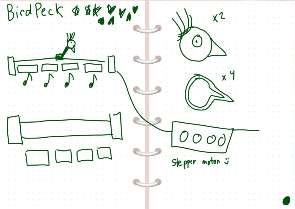
Hello and welcome to machine design and production week! Our assignment was to design, create, and document a machine that includes a mechanism, actuation, automation, and application!
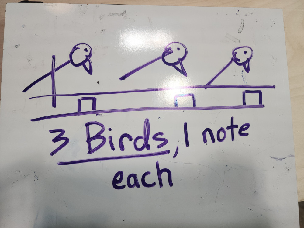
My teammate Angela and I do not have a fabrication or engineering background, this was a big adventure for both of us! We started off by brainstorming ideas of a device. that included both of our interests: motors and music! Our goal was to create a bird that would peck at something to generate music!
Scheduling
Our schedules were not aligned for this week. This week was also mid-term break. The plan was that I would work for the first 7 days developing the mechanism to make the bird peck up and down with a single motor. Then Angelea would come back and work on the coding + motors aspect. After 3 days, I would come back and help finish up with the xylophone keys, housing, and aesthetics. Since we only had 3 people, we added our instructor, Will Rudolph, to our group. His job was to make the xylophone keys and help refine the 3D model.
Cardboard Prototype
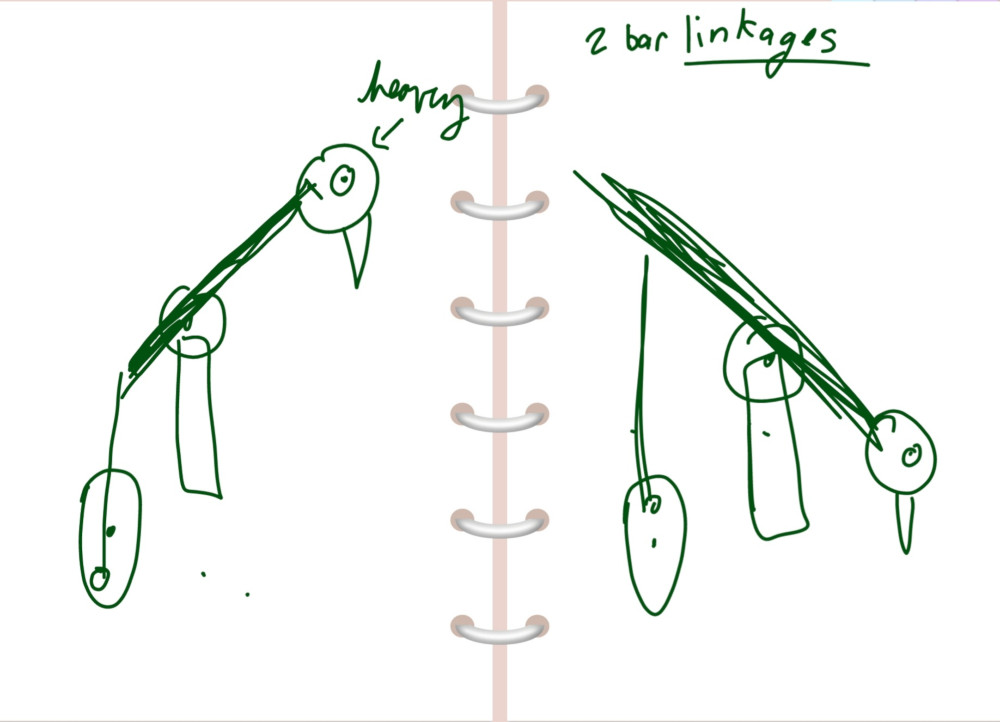
On day 1 I jumped straight into prototyping! I used cardboard,scissors, and tape to freehand an inital design. I was unable to describe to my classmates what I was imagining the mechanisim to be, so I made it! From this prototype I understood that I needed 3 main pieces to work
Laser Cutting
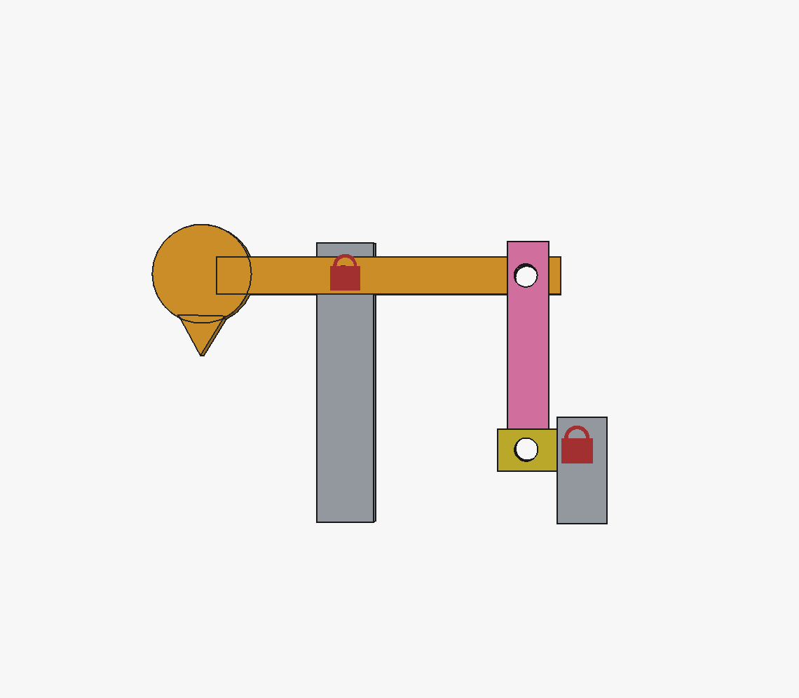
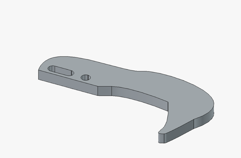
I started out with this design on FREECAD. At the time, my 3D modeling skills were based on my ability to make an SVG and extrude. This design is made of 5 parts, 3 of which move.
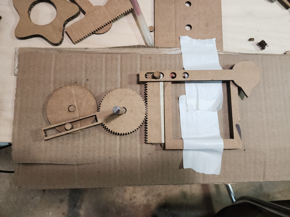
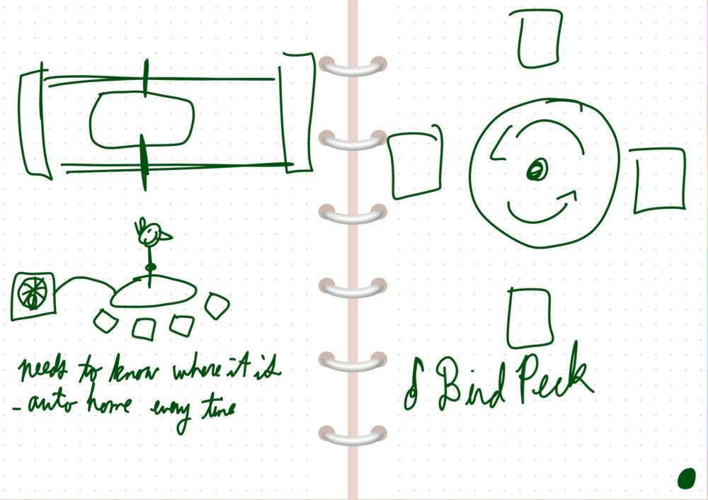
On the suggestins of the lovely instructors from Global Open Time, I changed my design from a series of rectangles connected by holes to do a rack and pinion deisgn. I used an extension on FREECAD called gear workbenck to create the gears. I created all the pieces as an SVG that I extruded to check fit.
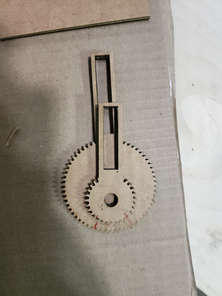
Trying to figure out the correct size ratio of the great to the rack was tough, especially figuring out the placement of the hole. In my initial tries, making the gear itself bigger or smaller didn’t change the distance traveled much. The red lines on both of these pieces mark the two extremes it would touch the rack.
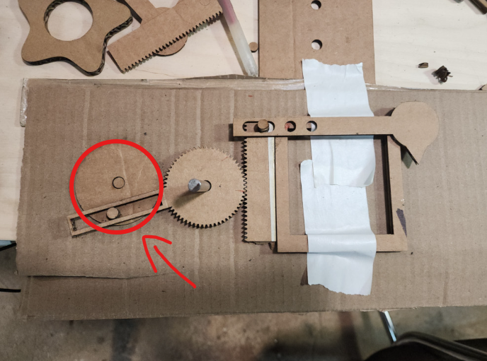
They key was actually to make this piece bigger!
3D Printing
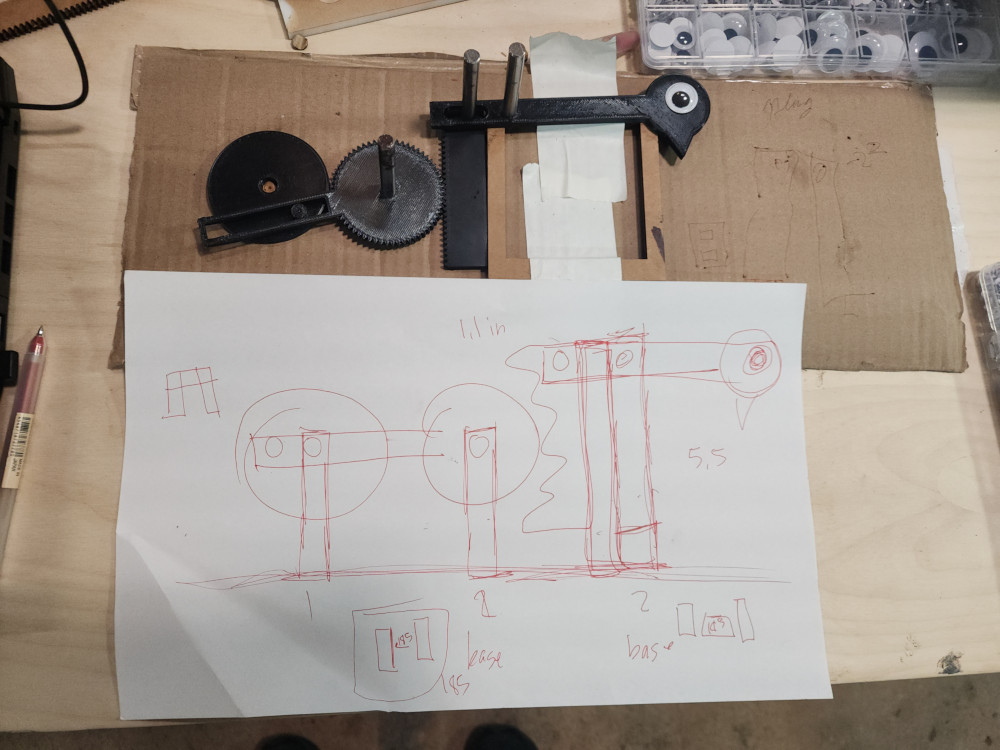
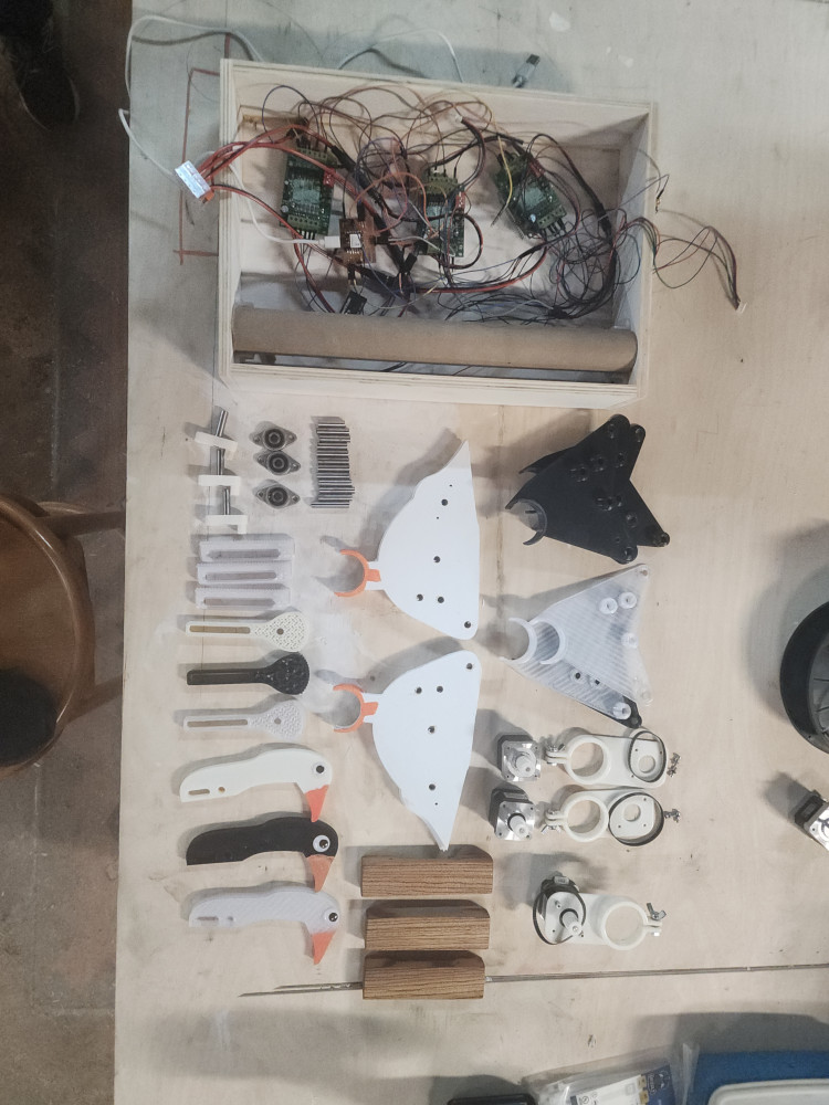
Once I got it all set up we sent it to the 3D printer! We had to go through many iterations to get the tolerences to slide correctly against each other. These pieces were made with PETG filiment. Once we verifies that all these pieces fit together we had to create a structure to make it upright!
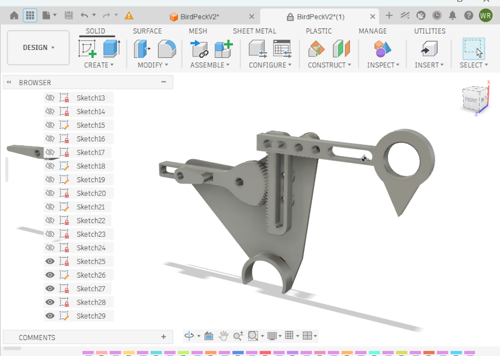
This next iteration you can see that improvements made. This is the design the Instructor refined. He streamlines the shapes to be smaller and more easily printable. This is a very important part of the prototyping, as it allows us to get through iterations quicker.
- the head is more hollow
- the turning circle has been compltly reduced to a round ovalish shape,
- the gear itself isnt printed all the way around, it only has teeth where it will interact with thte rack
- the rack now has a hole in the middle that we can anchor to the sides
- theres now a supporting structure that we can press 6mm bars into to assemble!
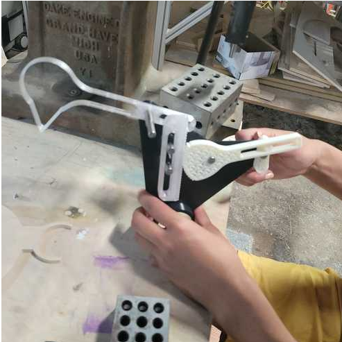
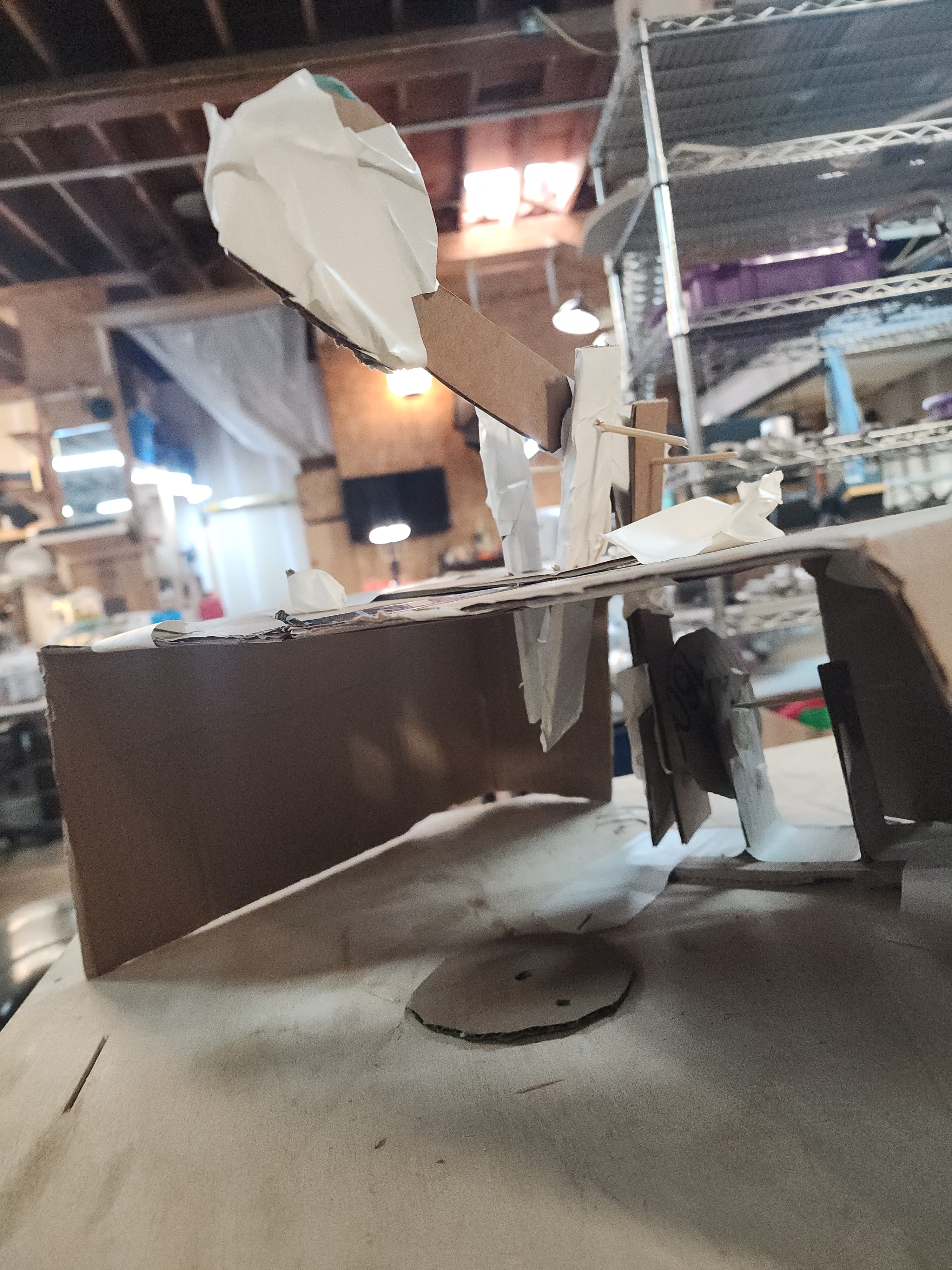
Here’s how it looks printed!
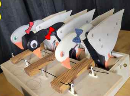
Aesthetics
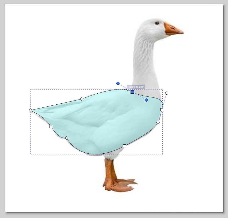
Aesthetics easily added about 5 more hours of work to this project, but it was worth it. We originally tried a woodpecker, or a duck. But the ratios weren’t looking right. So instead we modled it off a goose, because the long neck fit our design! I used Inkscape and traced out a design, then I overlaid it with the structure to line up the holes from the 3D printed supports.
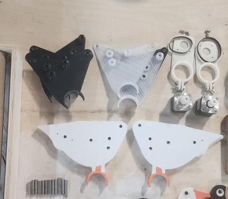
Next I laser cut the bodies out of 1/8th in plywood and painted them. This had a functional purpose. The nails and pressure of the belt from the motor were pulling at the 3D printed structure, so we reinforced it with plywood!
Next up was the goose head. Again, I traced over the model. I made sure to overlay it with our current bird head design to make sure that the hols and the peckers were in the exact same spot.
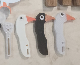
And this is the fun part! We were on a time crunch and used all 3 3D printers, but we didn’t have 3 spools of filiment. That is why the heads and bodies are different colors. I painted the beaks on each of them, and then we all got to pick what eyes to put on our goose!
Xylophone
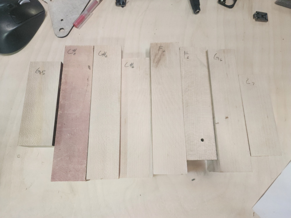
Will expirimented with xylophone keys. We used La Favre to guide us. These were cut out with the CNC. after some expirmenentation and reading we learned that keys like to be twice as wide as they are tall, and that if the height and width were the same, height determined the notes. In this picture I used an turning website to determine each note.
After the right keys were picked out ( F, G, A) I sanded and finished the keys.
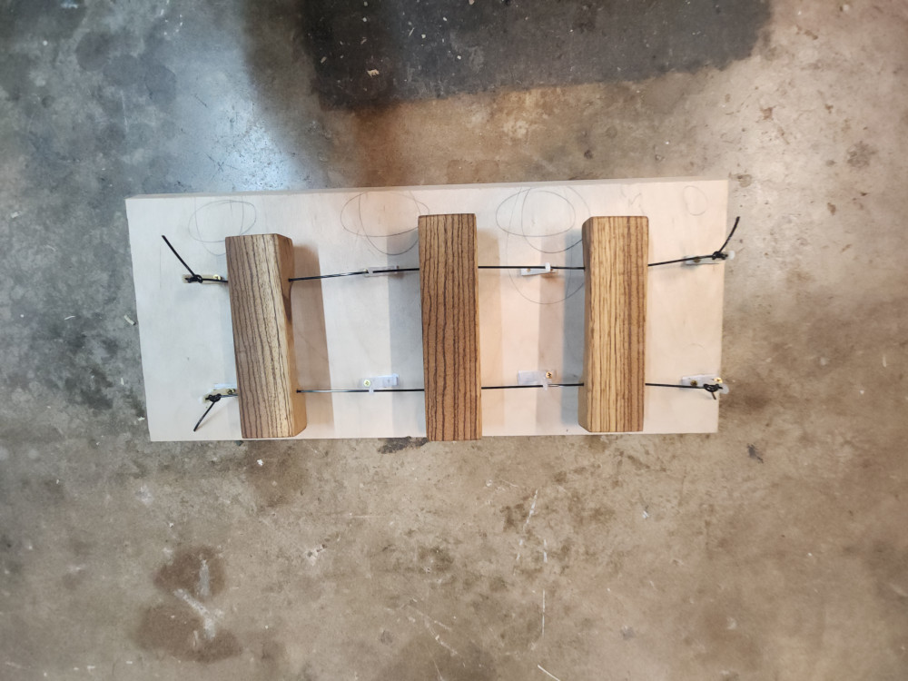
We also tested 3 different methods to see which one would produce the cleanest sound
- hanging on a string
- using rubber pins
- laying on styrofoam.
Hanging by a string produced the cleanest sound, and by far was the easiest to mount
I went into FREECAD to create a simple tool to string the keys through and keep them suspended.
At this point, we were so close to being done. My iterations of this suspender were taking longer than I thought it should. I realized it was the orientation that I was printing them on. Laying them on their side reduces the printing time by half!
Assembly
This is all out parts laid out together before final assembly!
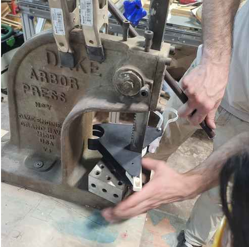
We used an arbor press to get all the poles through the slots.
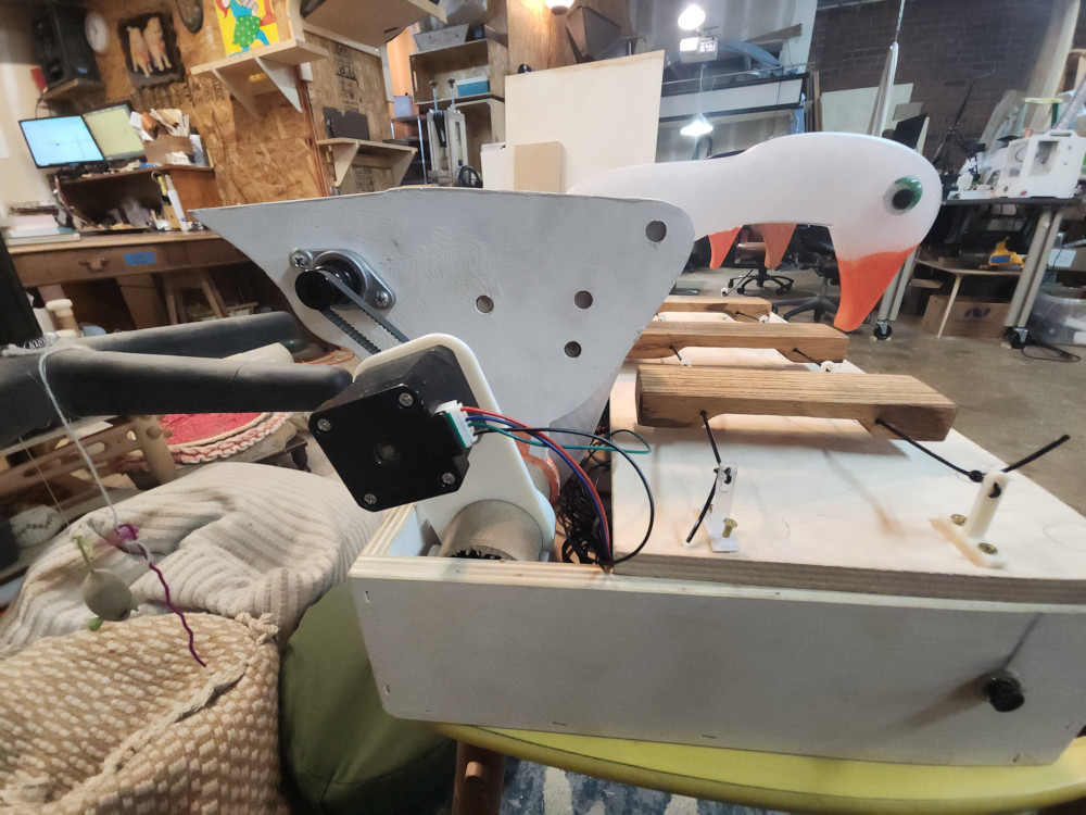
From this side view you can see that the keys just barely hover over the board. It took some time to position the Geese so that when they were at their lowest point they would hit the key. We also had to mess around with belt tension. We drilled the Geese “feet” onto their “perch” to keep them in place
Coding & Motor Control
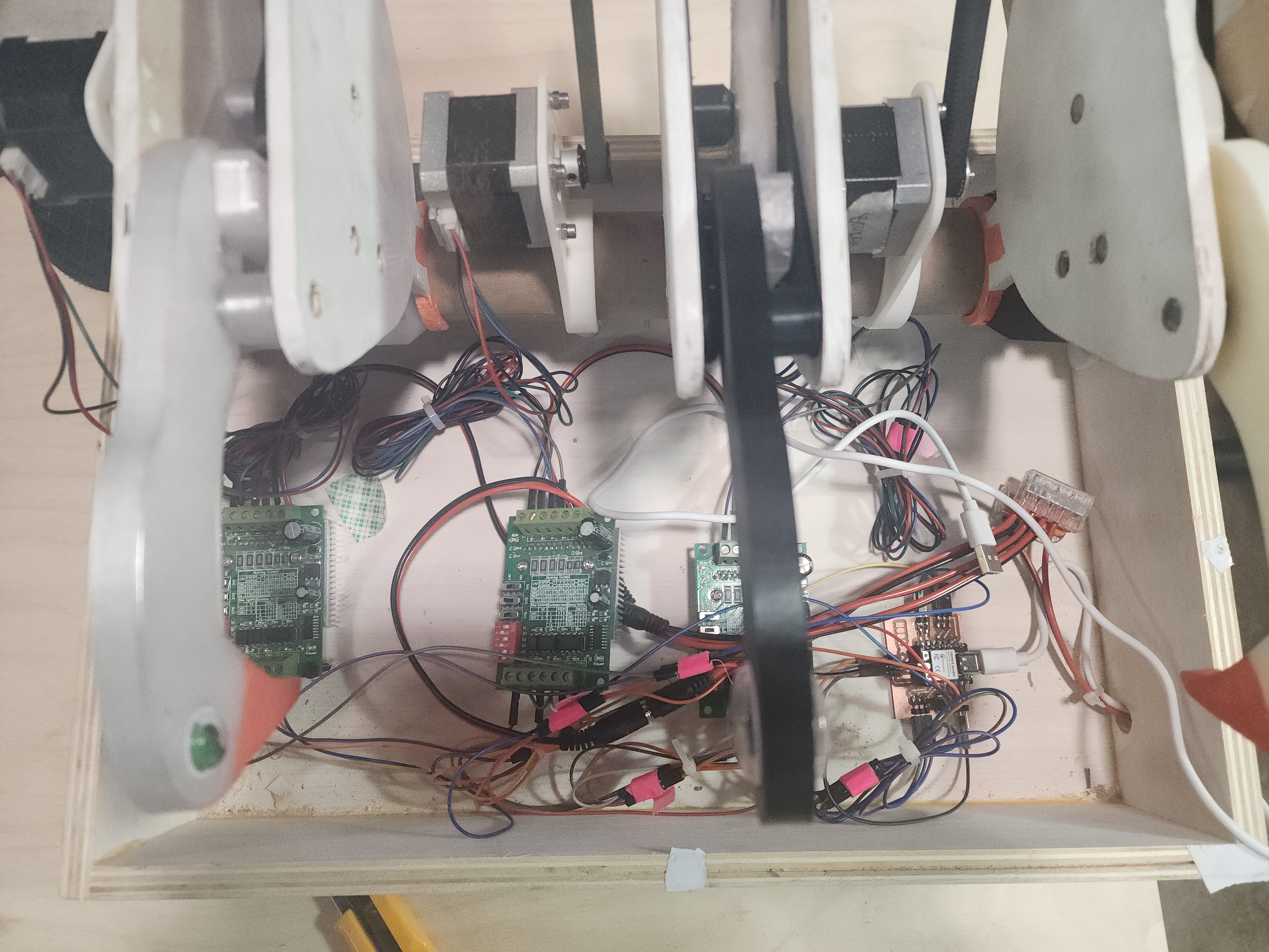
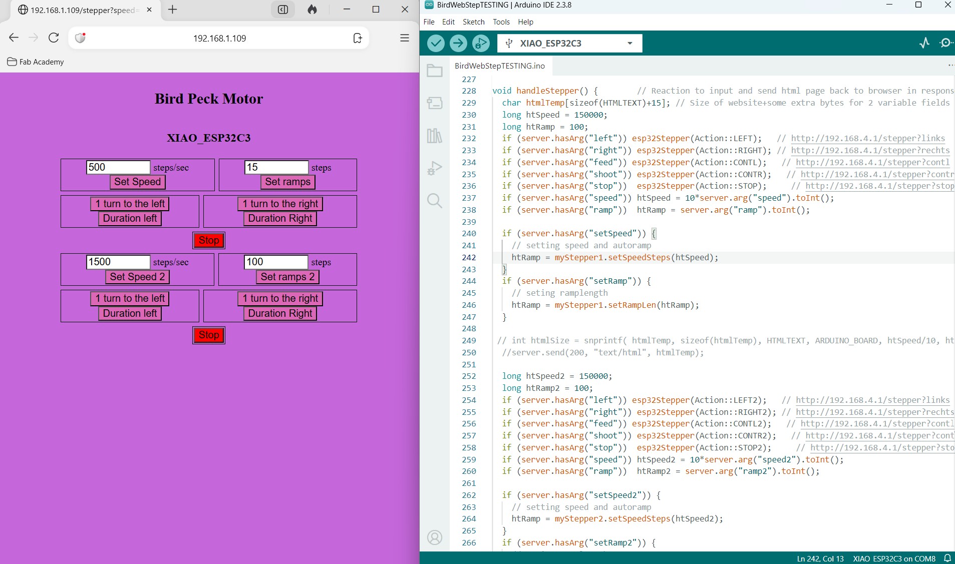
My teammate Angela did some truly amazing things with the motor and coding for this project. She created this UI to control the birds, however the website and directions were in German, so she had to translate it line by line! CLick Here to learn more about this amazing feat!
Reflection
This week was absolutely amazing! Angela and I had no background in fabrication, so to be able to make a machine completely from our imaginations and from scratch was life changing. If we had more time, I would have liked to switch our roles so we each took the part that we were weaker at. However due to the vacations and time crunch, we decided to stick to our strengths. Our schedule worked and we were on track for both weeks. However in order to do this we did pull a few late nights. Overall I’m very proud of the work we did together.
Groupwork
Click here to access our group page
Files
Cats!
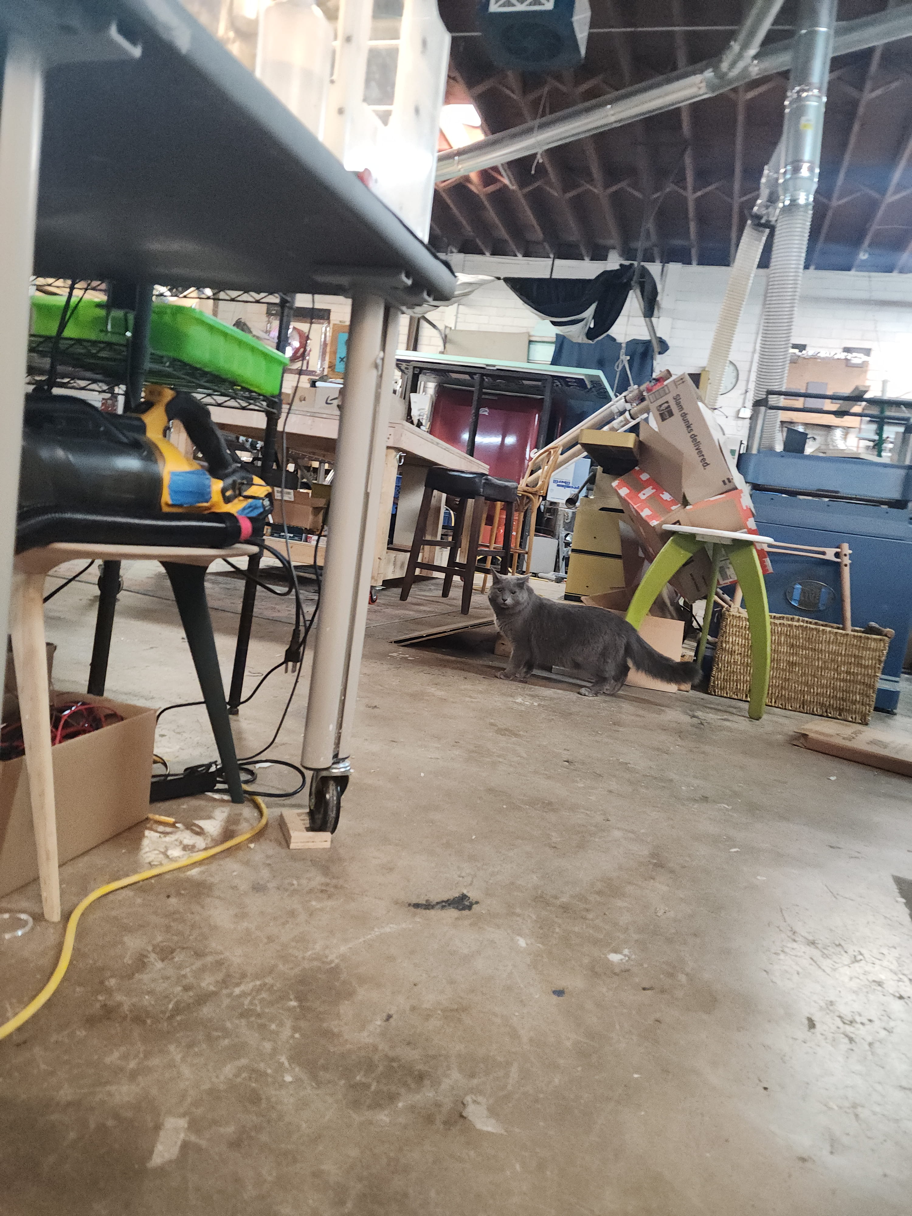
This week was a treat! I got to play will a small friendly cat named Oliver. Shadow knocked over a bunch of cardboard and then just looked at me, unrepentant.