Week 10: Output Devices
How I did it
This week is output devices! My final project involves controlling 10 LEDs with an accellerometer! I want the final project to look pretty, so the LED are arranged on a large circut board. I chose Neopixels so I could change the colors easily, and because Neopixels were the first thing I every played around with in code.

First off is making the plan! Connecting 10 NeoPixels together creates a wire mess, but I can do it!

The schematic was a little harder since I didn’t put them all in a row. Please note the cutout so that I can power the ESP32C3 with a battery later!
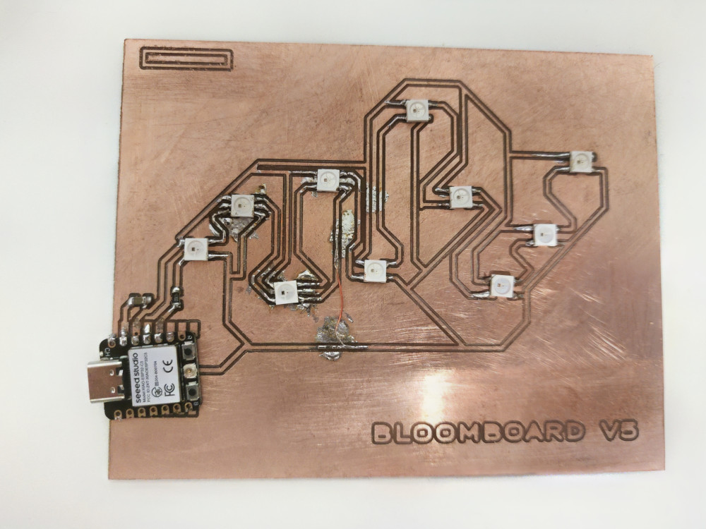
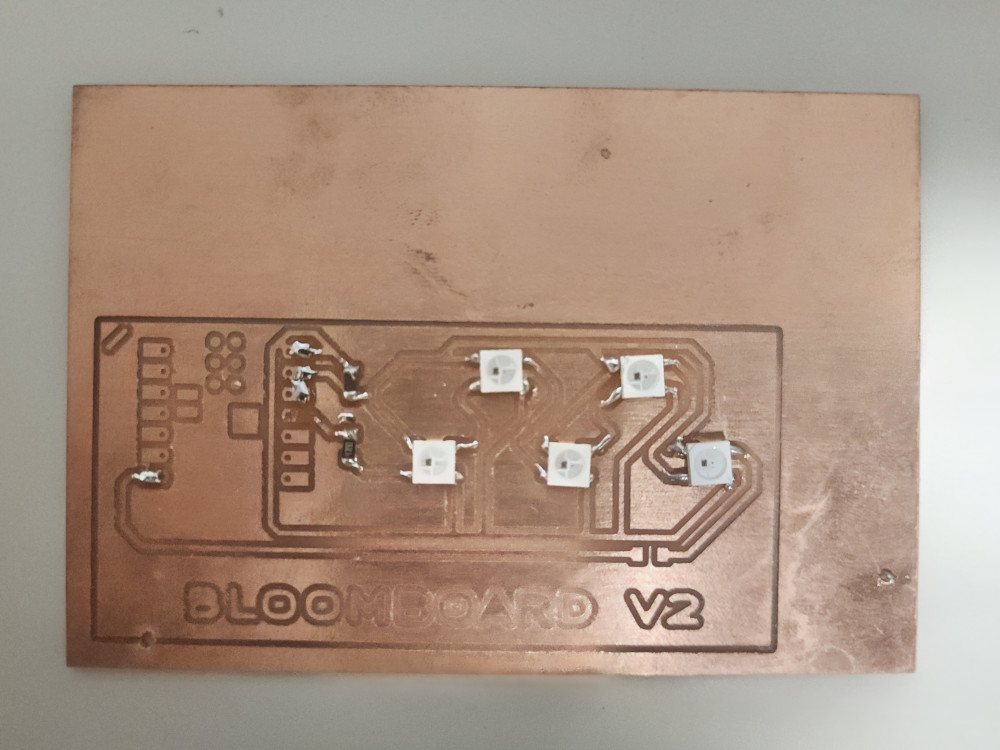
It’s all milled out, and would you believe I’ve tried 6 times already? But the board lights up! Version 1 only had 5 LED as proof of concept.
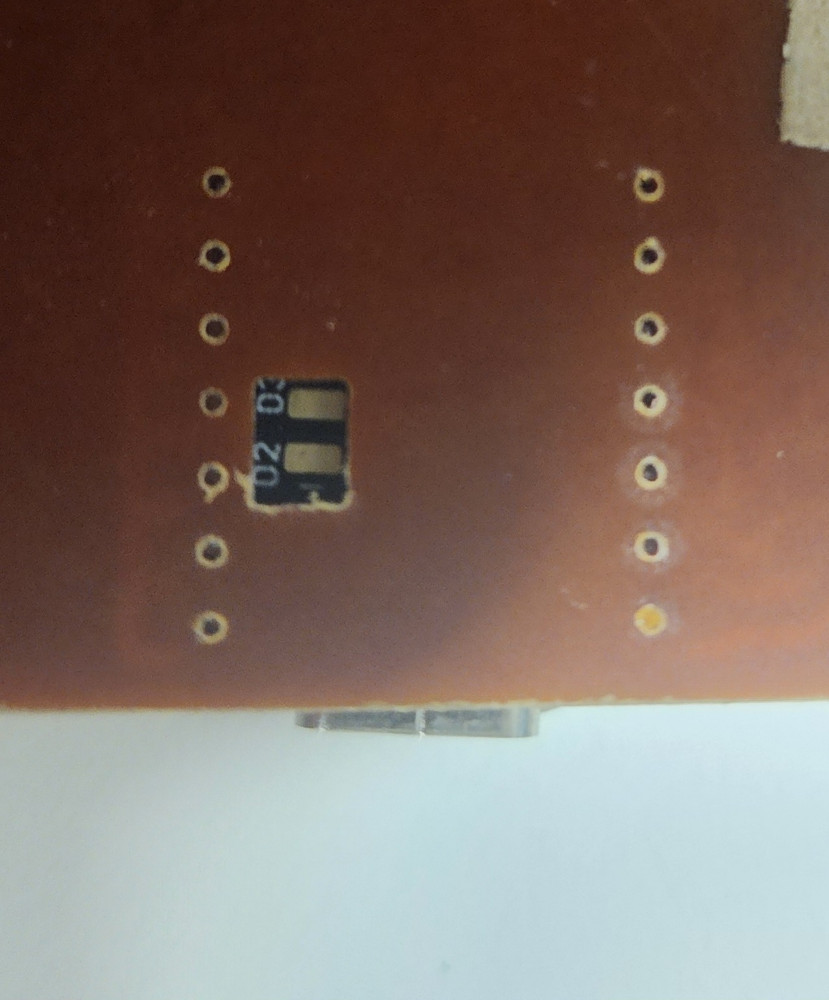
Also please note the mark on the upper left corner of the board, this is so I know which way the Neopixels need to face, they also have a mark in the upper left corner.
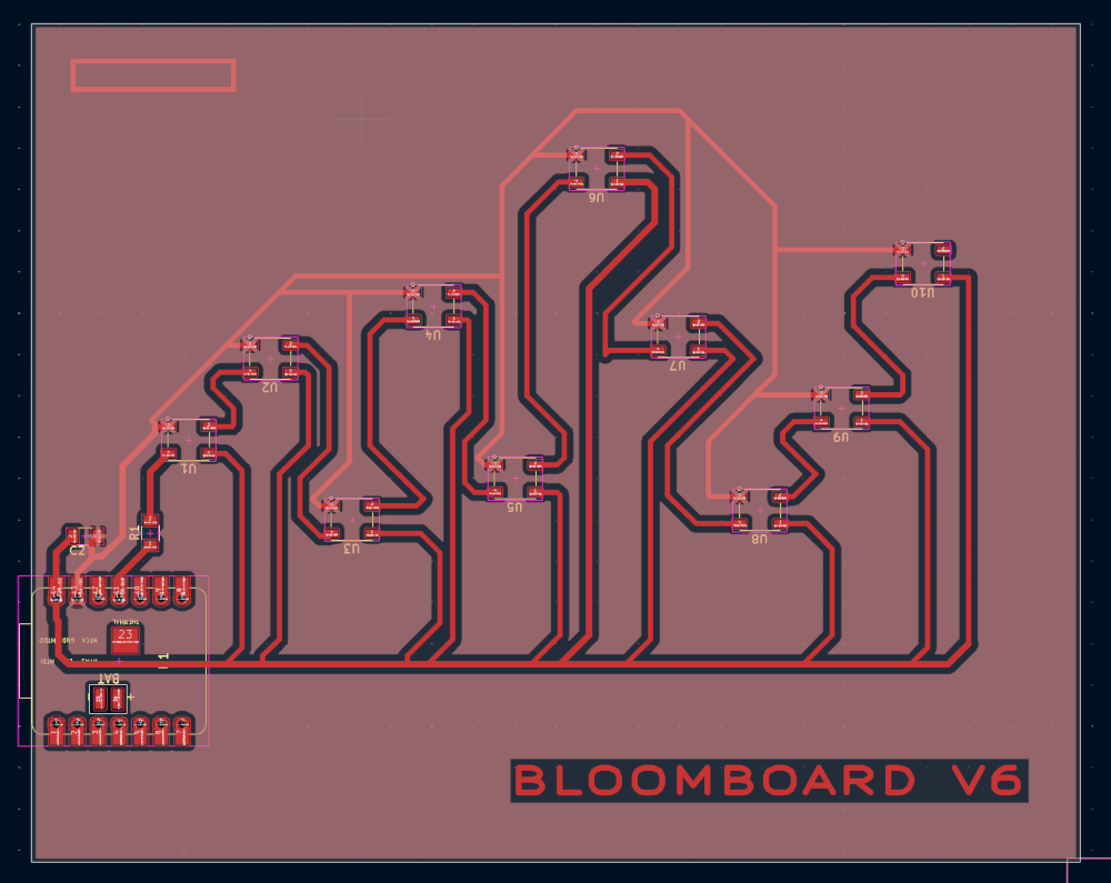
Currently I am at V6. I am hoping that making a HUGE ground fill plane will make it easier and faster to solder. My last fully functional board was V2.
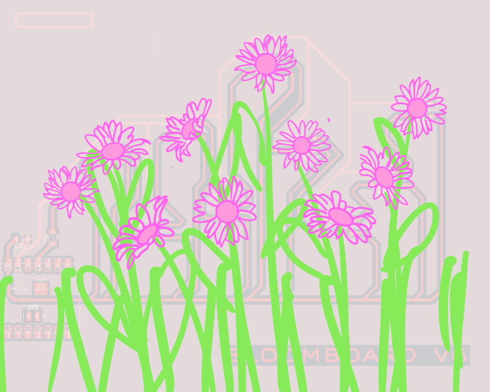
A small peek at my final project. Each Neopixel will be a flower in a flower field!
Code
I used the AI LM Studio to create the code. I used the AI model Gemma 4 E4B Instruct. I wanted to generate a code that works as a timer. There are 10 flowers, they turn on like a progress bar, where a new light turns on and stays on every minute. After all NeoPixels are one, they all turn off. Each cycle of 10 min is a new color. yellow, the blue, then white.
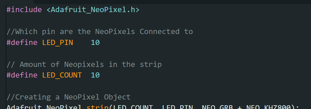
This section is the library, telling it what pin the strip is connected to, and how many are connected to the strip
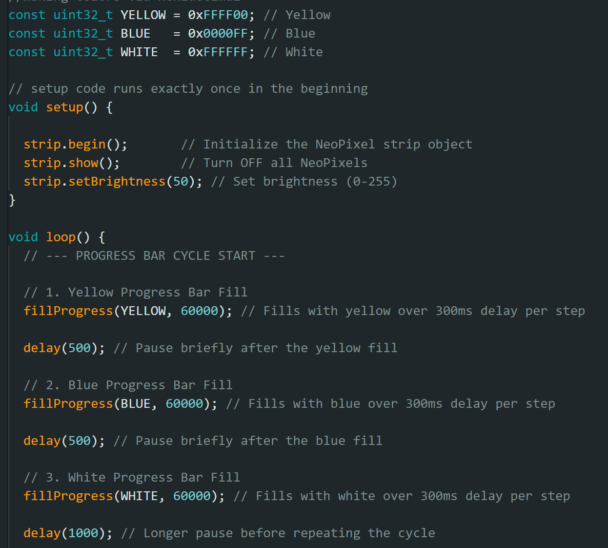
This section defines colors
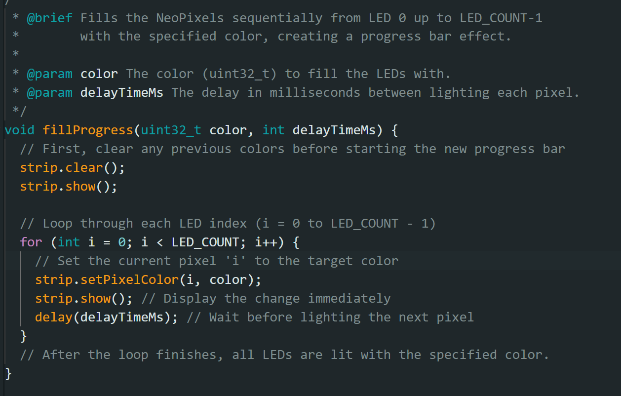
This section actually declares the loop and how each light turns on.
Overall, generating code was easier than writing it. However, it took some trial and error to explain to the AI what I wanted it to do. Often, it would write code that only turns on one light at a time, or turned all lights on but didn’t loop it. I was able to get a successful code by saying I wanted the lights to turn on like a “progress bar”.
Troubleshooting
Finding the correct resistor size and capacitor size was difficult. I used a 1uF capacitor and a 470 resistor. Although the math was very simple, I kept getting uF and nF mixed up.
The neopixels were tiny, kept flying off, and the housing kept melting. I fixed this by taping the neopixels down. I did try reflowing, but I found that taping + normal soldering was faster.
On Bloomboard V5 I forgot to wire some of the neopixels to 5V. This caused only those two to not turn on,
On Bloomboard V4, I wired the Neopixels to 3V3, because I heard tht if I use battery power it will only output 3V, The neopixels did not work at all. I also started vutting out the battery hold for later
On Bloomboard V3, I ripped off a copper pad. I used the coper wick to create a false bridge to connect the pad anyway, it worked!!
On Bloomboard 2V I only did 5 NeoPixels to test
On Bloomboard 1V I forgot the resistor
Reflection
Another week of highs and lows. Originally I wanted to make a motor for my original final project idea. However I got sick for 3 days and had to simplify. Switching to NeoPixels did not save as much of my sanity as I thought it would. Each Neopixel is an independent component that Relies on the previous to work.
Groupwork
Click here to learn more about measuring output decives
Cats
The cats found a new place to lounge!
Files
Conversation to generate code can be found here
Copyright 2026
Source code hosted at gitlab.fabcloud.org