Week 08: Electronics Production
How I did it
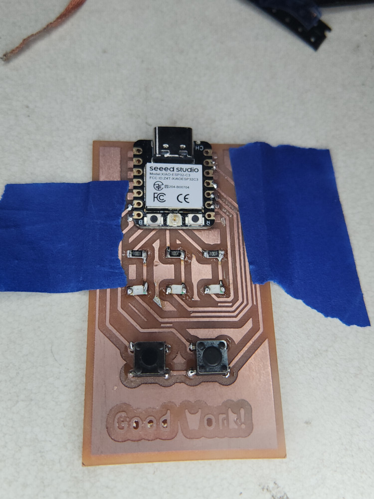
Using Kicad, I created a board. My goal was to create a board with 2 buttons and 3 LED. Yellow, green, and blue.
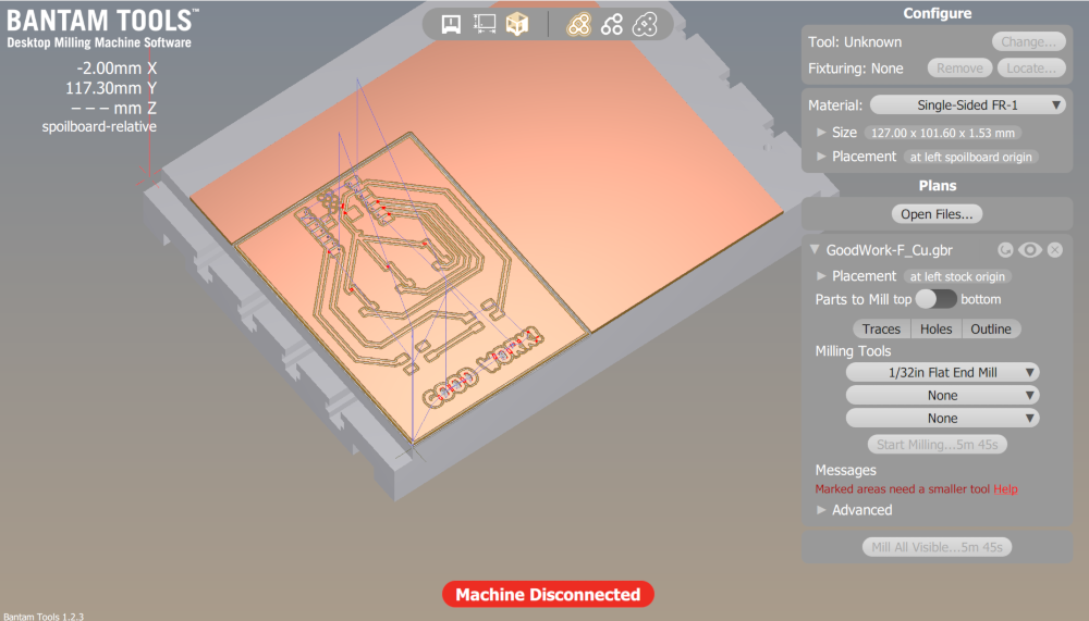
I used the program Bantum tools to create a milling path for my board, double checking that the paths were set correctly. It is important to home the machine and set the material thickness. The program makes this easy by giving it prompts
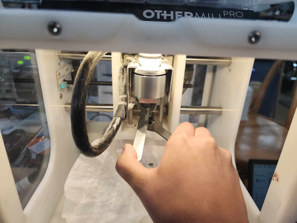
The actual process of milling is quite easy, when I need to change tools to make a smaller cut the program will prompt me. It is the same process as changing tools on the big CNC.
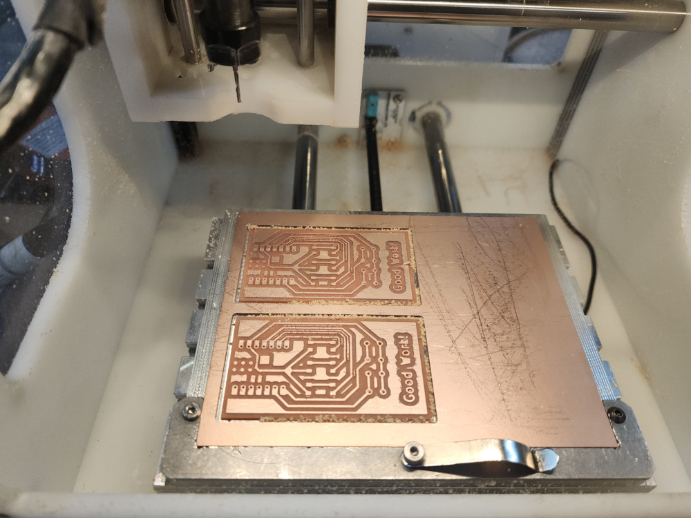
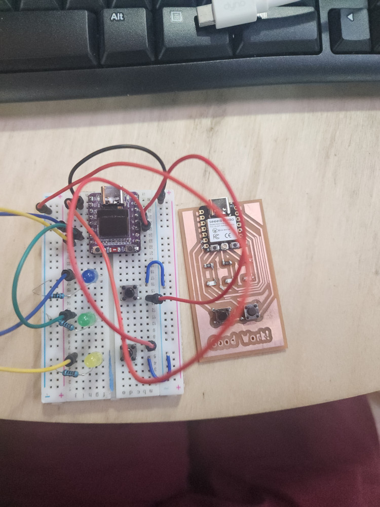
Now the board is all set!
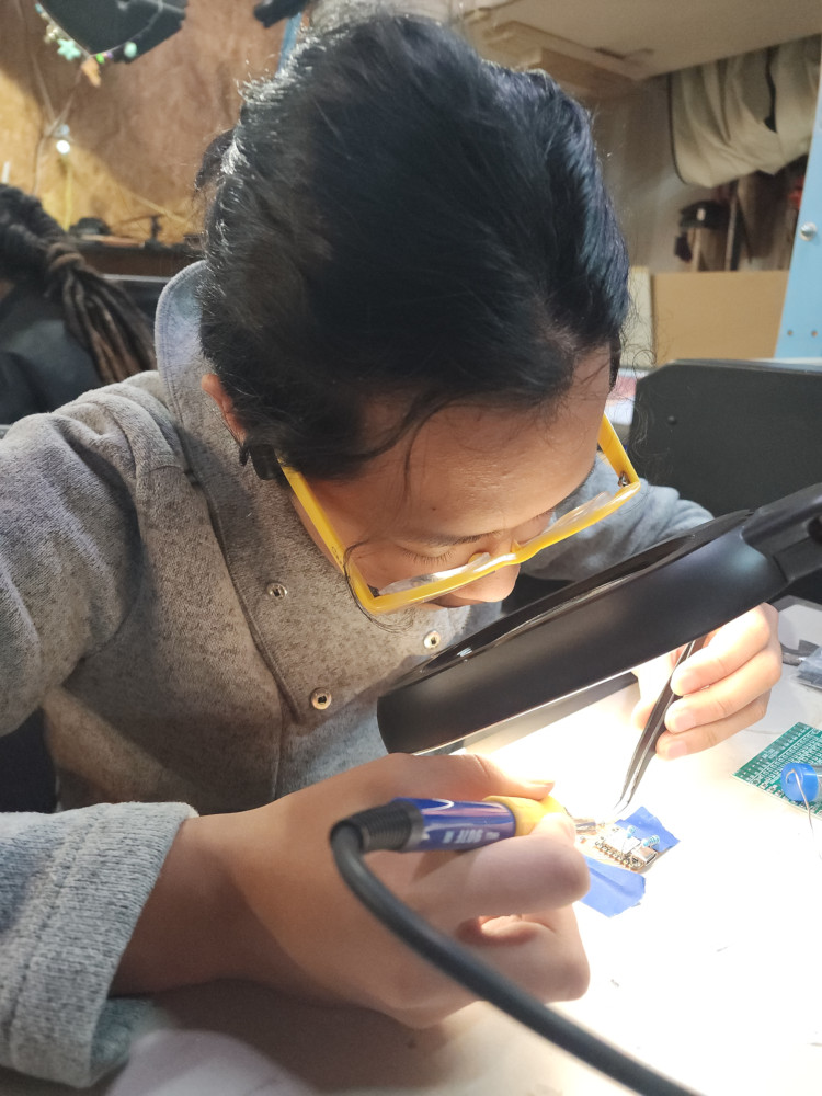
I am new to soldering, I tried out different thicknesses of solder, making sure to keep the exhaust on and putting the solder pen in it’s holder and not on the table.
success! I used the multimeter to confirm all the connections
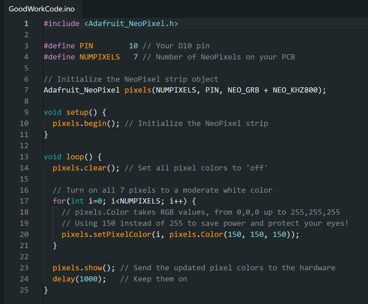
For coding my goal was that if you press the left button, the yellow LED turns on. If you press the right button, the blue LED turns on. If you press both, the yellow and blue turn off, and the green LED turns on.
I had great difficulties with the coding. Unlike last week, when I was using a neo pixel to decide color, the LEDs just had one. All I had to do was get them to respond to a button. My code logic was solid. Eventually I asked my brother, and engineer, to take a look. He gave me this code and explained everything.
When I plugged in the code it did not work! It did the opposite of what I wanted. This is an easy fix, I just wrote the word not in front of the lines. But I didn’t understand why it was doing this.
The reason this happened is because I had wired the LEDs and buttons to ground. It created a full circuit so they were “pressed” and “on” by default. If I had wired them to be connected to the Power source instead this would not have happened.
Troubleshooting
** Q: My program won’t let me carve out all the details I want, what do I do? **
A: Use a smaller tool, or move the circuit lines farther apart.
** Q: How do I get solder to stick to my board? **
A: Use Flux! It is a compound that cleans the surface of your board and helps you make a good joint.
** Q: I accidently put solder down and now 2 things are connected, how do I fix that? **
A: Solder wick is your friend. It is a woven bit of copper embedded with flux. You place it on top of the the accidental solder and heat it up. It will melt the solder and remove the extra solder.
Reflection
Overall, I found this process difficult. In 1 week I had created a design, learned how to use a new machine, soldered for the first time, and tried coding again. All new things to me. Neil described the first time being able to code a light to turn on as life changing. I did not feel that last week. However this week I gained a much more through understanding of code and troubleshooting. I made something a little more complex, that came from my own imagination. It was life changing.
Groupwork
Click here to learn more about characterizing our mill
Cats

Files
Copyright 2026
Source code hosted at gitlab.fabcloud.org