Week 09: Input Devices
How I did it
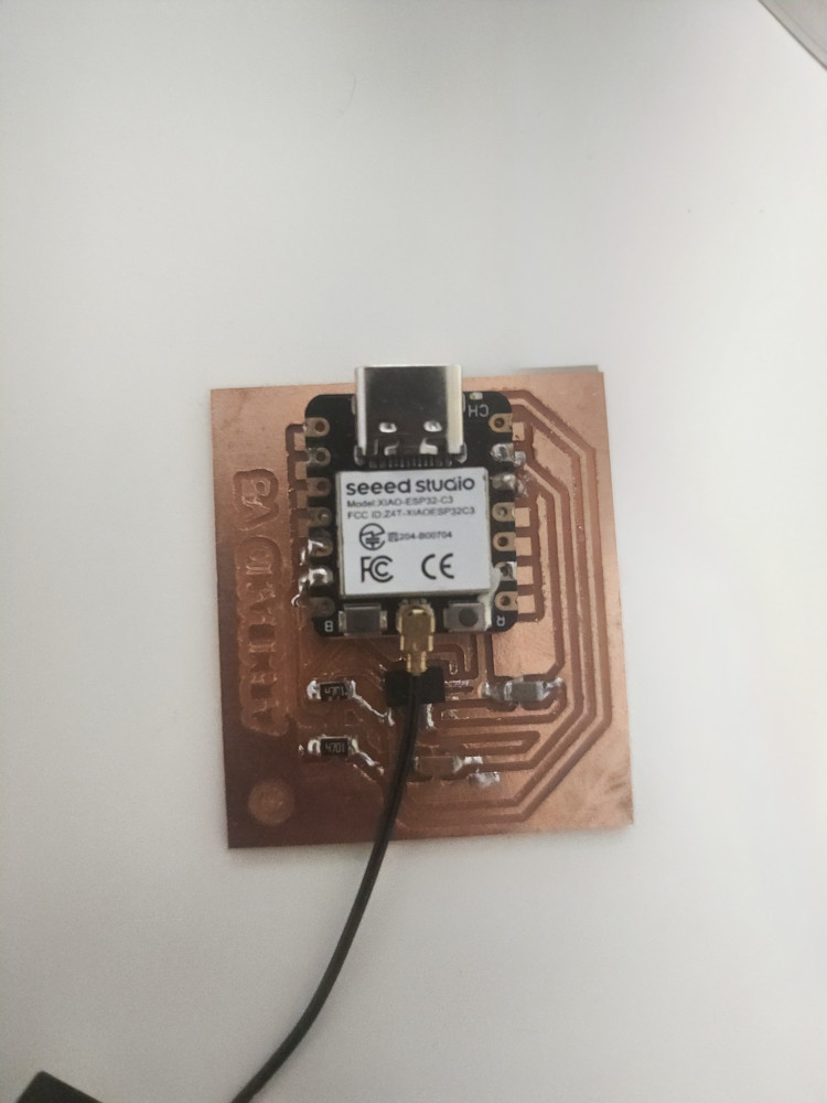
Since my final project involves attaching a movement sensor to a motor, I decided to use an accelerometer. I used the ADXL343 because it is in the PCM fablab folder in KiCAD.
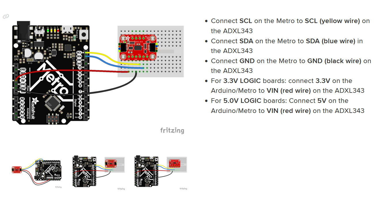
I used this guide To follow along and learn how to wire her up. They include code to write in! These number are the movement of her! she is an absolute positional sensor. That means she give me numbers based on where she is in the world.
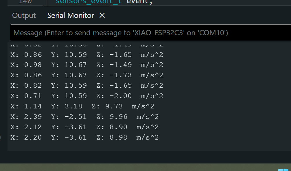
Based on the x value you can see if shes high or low. You can see here that it detects the change in direction when the coordinates change.
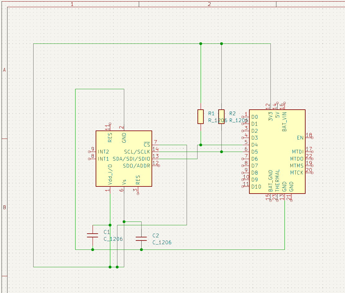
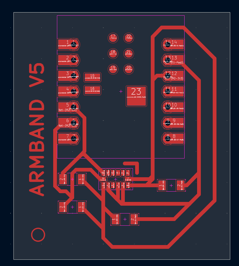
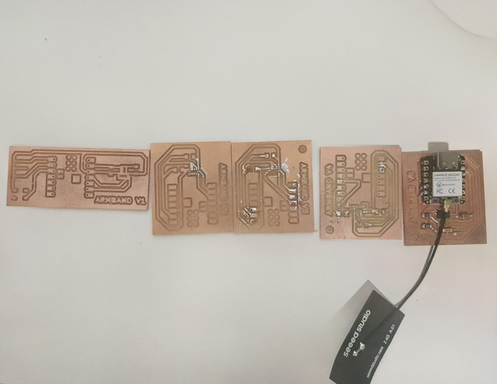
Next up was creating a design to attach board. I needed 2 resistors and 2 capacitors. The guide says to connect the 3V3 pin to the CS pin. But I actually needed it connected to both the CS pin, the Vs pin, AND THE Vdd pin. Knowing I needed to add all these components easily added 5 iterations alone.
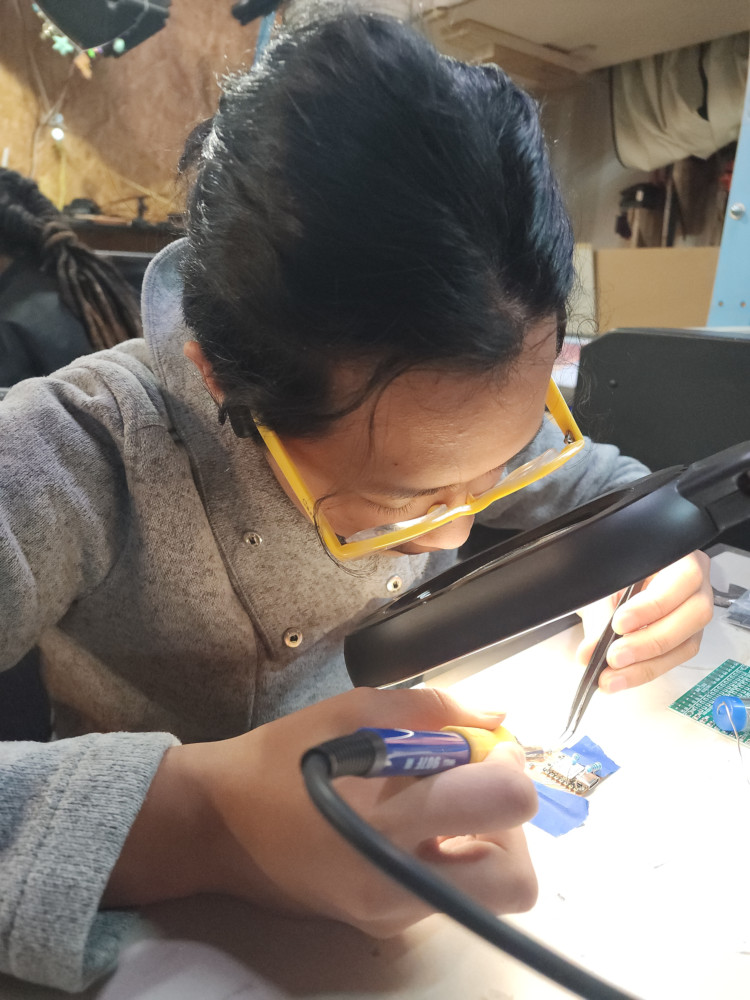
Then I soldered it all together
Success!!
Code
I used the Adxl343 Library in Arduino.
Troubleshooting
The LIS3DH caused so many issues I thought I was going crazy. I eventually switched to the ADXL343 so that it was smaller and would actually have a KiCAD footprint.
It did not have a KiCAD footprint
I changed the wiring. the exact same wiring worked on my classmates laptop with the same code. It was the LIS3DH that was broken. Because the code worked when I used a different one.
The ADXL343 was so tiny I had to learn reflow. This is when you place solder on the pads and small amounts of solder. Next you line up the ADXL343 where you want it to be, and then use a heat gun to melt the solder into pace. In larger commercial settings, this is done with baking in an oven. Many datasheets include data on the temperatures their chips can withstand. This can be difficult. If you mess up you may rip the copper plating off your board. I ripped up a copper pad and had to remill.
Code
So, I didn’t write any of my own code this week. I didn’t even have to change the code to get this to work. this is my understanding of how it works.
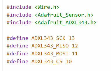
This include libraries and tells you which pins each part is wired to. While I was troubleshooting I played around with the pin numbers. They way I had my board wired meant that it connected automatically, telling the board which pins are where doesn’t matter at all in my case.
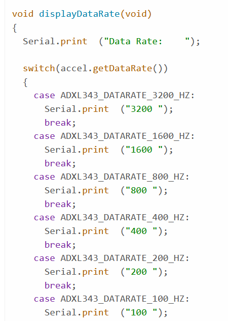
This section is basically saying, if you sense 800Hz, print 800 Hz, and repeats for each number
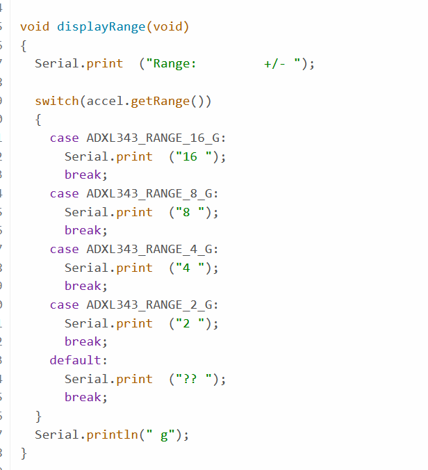
This section sets the range of values
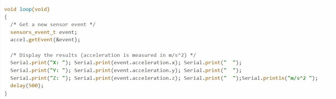
This one prints out the X, Y, and Z coordinates.
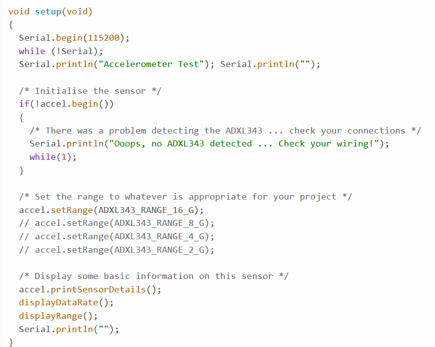
This section tells you if it cannot sense the ADXL343.
Reflections
This week I learned that debugging is a huge part of the fabrication process, and that knowing how to debug is important. It does not mean I failed the project. I also understand now why there is a huge emphasis in FabAcademy around documenting failures. For something as simple as learning to attach a movement sensor, there only needs to be 1 guide on how to do it correctly. What is far more interesting, and useful, is documentation on all the ways it has gone wrong and how to fix it.
Groupwork
Click here to learn more about multimeters and Oscilloscopes
Cats
The cats long to smell and taste my food, yet they never eat it. Even when it’s unseasoned pork.
Files
Copyright 2026
Source code hosted at gitlab.fabcloud.org