Week 12: Mechanical Design and Machine Design
Our assignment:
Group Assignment:
Mechanical Design1. design a machine that includes mechanism+actuation+automation+function+user interface 2. build the mechanical parts and operate it manually 3. document the group project and your individual contribution
Machine Design 1. actuate and automate your machine 2. document the group project and your individual contribution 3. prepare a demonstration of your machines for the next class _
Individual Assignment: Document your individual contribution
Group Assignment: Bird Peck!
For our group assignment, we decided to make a bird pecking machine Find our group documentation here and my documented contributions and learnings below.
Individual Assignment
My contribution to the group assignment included motor testing/operation, developing code for operating our machine as ideas evolved, electronics production and wiring management, mounting motors and gears, and support with overall assembly and troubleshooting. I also created the powerpoint and contributed to overall documentation.
Motor Testing: DC Motors
To operate the machine, ultimately, we ended up using three stepper motors. To get there, I spent many hours learning about and testing various motors and motor drivers.
Micro Servo 9g A0090
First I tried using the Micro Servo 9G A0090 since it would be safe to run with the power supplied by a microcontroller.
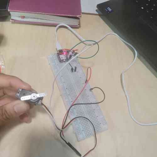
Micro servo breadboard circuit.
DC Motor with an L298N Motor Driver Board
With some setup help from Will, I next tested a DC motor, using an L298N motor driver board and power supply.
This L298N Motor Driver Board guide provided a good overview. I learned that the driver has a 5V voltage regulator (it can take a maximum of 12V) where it creates a separate circuit managing the 12V. This allows us to set the flow of current through whichever pin is high or low by using an H-Bridge. A jumper cable connects 12V to the voltage regulator. And even though supply voltage isn't being shared, ground does need to be shared.
With the proper wiring and code, you can control the spinning direction of the motor by switching HIGH or LOW the Input (IN1/IN2, etc.) channels. You can control the speed of the motor by adjusting the Pulse-Width-Modulation (PWM) via the enable pin (ENA/ENB). A higher duty cycle of the PWM results in higher speed of the motor.
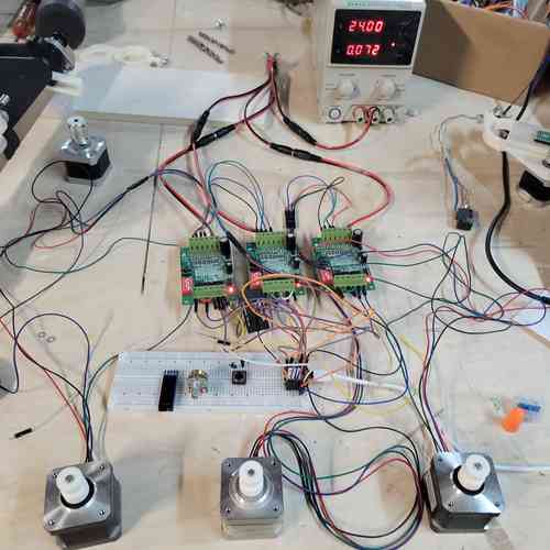
With this and remaining motor testing, we used the power supply equipment in the lab which was made it easy to set voltage and be mindful of current.
Eventually, found this code on Random Nerd Tutorials which worked for running a test run (also in design files). After getting this to work, I messed with the code to get a better sense of how to control speed. As the Random Nerd Tutorial summarizes, switching the HIGH/LOW values of inputs 1 and 2 will control the direction of the motor, forwards or backwards. The speed of the DC motor is proportional to the duty cycle so sending a PWM signal to the enable pin will control speed.
Next tried with two motors:
Two motors running
DRV8251A 4.1-A Brushed DC Motor Driver
Will created a motor driver board using a DRV825A device data sheet here. Since Castor's progress led to a mechanism where the bird motion was periodic with the same motor direction rather than needing the motor to go forwards then turn around, I began focusing on using DC motor while getting sharper on speed regulation.
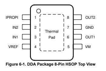
Pin out of the motor driver device from the data sheet
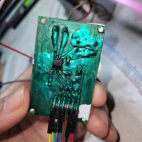
Will's board
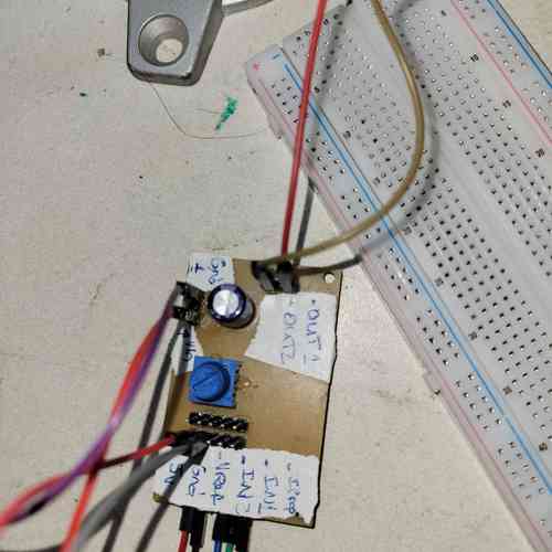
The underside of Will's board with helpful labelling!
This board has pins for connecting to the motor (OUT 1 and OUT 2), pins for connecting to motor's power supply (VM) and ground (GND), pins for connecting to logic inputs (IN1 and IN2), pin for analog input (VREF - this is hooked up to a potentiometer on board), and finally a pin for connecting to the Analog current output proportional to load current (IPROPI).
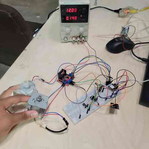
Then, I ran test code below for operating the motor. Since there was no enable pin, this made the coding a bit simpler. I did make use of the IPROPI pin and had the analog read values printed to the serial monitor.
// Simplified code for running a DC motor through DRV8251A motor driver

// MOTOR A: define pins connecting to motor driver board
int IN_1 = D1;
int IN_2 = D2;

// define speed
uint8_t speed = 0;

void setup() {
// MOTOR A: setting pins as outputs
pinMode(IN_1, OUTPUT);
pinMode(IN_2, OUTPUT);

Serial.begin(115200);

Serial.print("Testing DC Motor..");

}

void loop() {
// Move DC motor forward at specified speed
Serial.println("Moving Forward");
analogWrite(IN_1, speed++); // moves motor at increasing speed
digitalWrite(IN_2, LOW);

// brake motor at certain speed
if (speed > 200) {
    digitalWrite(IN_2, HIGH);
}

// Read analog input values
int IPROPI = analogRead(A0);
Serial.println("IPROPI Reading");
Serial.println(IPROPI);

delay(100);

}
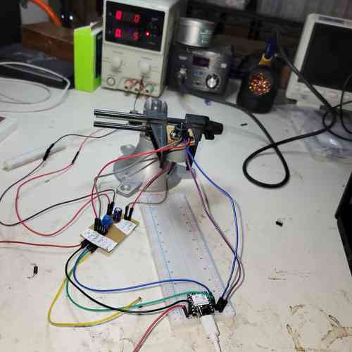
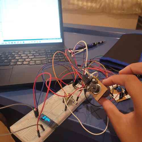
Set-up for running tests with this motor board device
Applying Motor Encoders
At this point, our project idea evolved into users being able to set the speed. We have these motor encoders (clicking he dropdown menu under encoder test provides downloads for assembly instructions, test procedure, and test program) in the lab which can be mounted around the motor along with magnets to essentially sense speed.
This guide by tinkimo gave a helpful overview on the uses of motor encoders. It explains that as the motor shaft turns the encoder generates electrical pulses which can be counted within the code to determine different information (I'm interested in speed). "In simple terms, the encoder turns a basic spinning motor into a measured, controllable movement system." The encoder has two pulse connections ("A" and "B") and with one signal the encoder can count movement; with two, it can measure both movement and direction due to a small offset of the sensors. For this project, I'll just need to use one pulse connector.
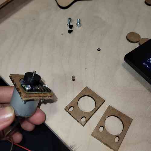
Needed to create a laser cut for the mounts so on to Inkscape and laser cutter I go...
After making the needed measurements with calipers I created a few options:
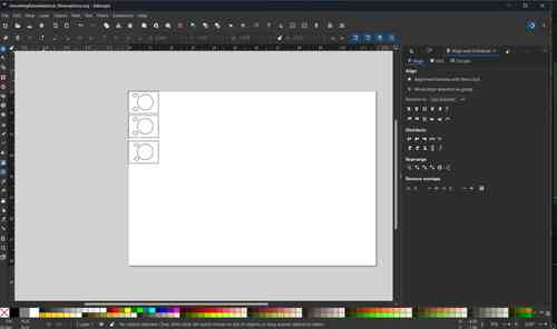
Design for mount on Inkscape
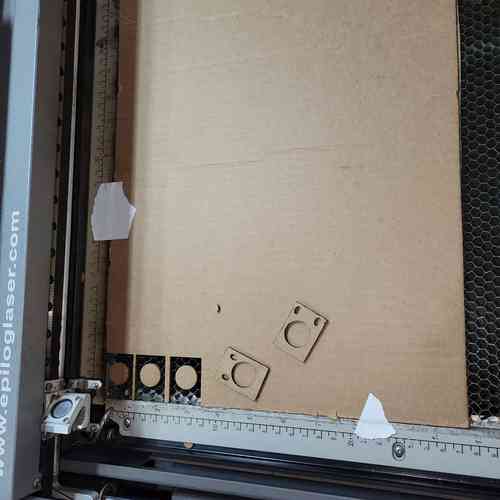
Cardboard cutouts of mounts after laser cutting
After hooking up the encoder, I tested using it with some test code.
Here was some simple test code used that counts movement detection in the serial monitor:
// Code to test encoder made with assistance from Will for Fab Academy 2026

// Define encoder pin (this code just uses one)
#define ENCODER_A_PIN D7

// MOTOR A: define pins connecting to motor driver board
int IN_1 = D1;
int IN_2 = D2;

// define speed
uint8_t speed = 0;

// store state of the detector of the encoder - current and prior state of the encoder
bool detectorState;
bool detectorState_prior;

// initialize detector counter - variable we're going to increment every time we detect a state change
long detectorcounter;

void setup() {
// MOTOR A: setting pins as outputs
pinMode(IN_1, OUTPUT);
pinMode(IN_2, OUTPUT);


Serial.begin(115200);

Serial.print("Testing DC Motor..");

// define pin modes for the encoder
pinMode(ENCODER_A_PIN, INPUT_PULLUP);

}

void loop() {
// Move DC motor forward at specified speed
Serial.println("Moving Forward");
analogWrite(IN_1, speed++); // adds 1 to the speed every loop
digitalWrite(IN_2, LOW);

if (speed > 200) {
    digitalWrite(IN_2, HIGH); // brakes the motor when speed is above specified value
}

//store prior detector state from previous loop
detectorState_prior = detectorState;

// read current state of detector pin
detectorState = digitalRead(ENCODER_A_PIN);

// incrementing variable by 1 when change from current to prior detector state
if (detectorState != detectorState_prior){
    detectorcounter++;
}


// Print detector counter
Serial.println("Detector Counter");
Serial.println(detectorcounter);

delay(100);

}
To generate more advanced code, I prompted qwen3.6-plus using the prompt attached here. Essentially, I prompted it to create code that would allow for the speed of the motor to be controlled by a potentiometer while displaying this in the form Beats Per Minute on an OLED screen.
I spent a while debugging the code and my wiring. At this stage, turning the potentiometer does change the speed of the motor but it isn't very reliable and it is also flipped. Another issue is the actual vs target speeds had huge discrepancies.
Looked into this encoder library for more information and to attempt debugging the code.
HEDS-9040 Encoder
Next, I learned about using a DC motor with an encoder included. The motor used had an HEDS-9040 encoder. I hooked up the motor and encoder and ran basic test code to verify it was working. This time, I used both channels A and B.
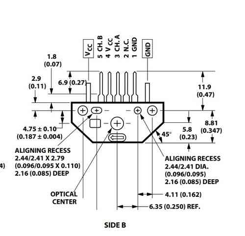
Pin-out of the HEDS-9040 Encoder
Looking at the serial monitor, the encoder was running but soon I found that once I started supplying 21V and above to the motor (it's a 24 V motor) the counting would no longer work.
Motor Testing: Stepper Motors
Stepper Motor Learning
For our machine, I had to consider the differences between DC and Stepper Motors. The DC motors can certainly go fast, but stepper motors are easier and more precise to control. I needed to determine if they could go and accelerate fast enough to do our bird pecking tasks...TLDR: it was!
I found some online resources: this comprehensive guide on using stepper motors with Arduino and this guide on using stepper motors with the L298N driver. The stepper motor is cool because on the inside it has a perimeter of wrapped up coils/electromagnets (called a "stator") that organize their charge in such a way that controls an inner magnet ("rotor") by activating the coils via electric current which either attracts or repels the rotor step by step (hence the name "stepper motor").
My first attempt using the stepper motor with an L298N Motor Driver board with example code gave me trouble. But I learned a trick described in links above to determine the proper wiring because you need to know which two pairs of wires are connected to each coil (from there polarity doesn't matter).
RAMPS1.4 Board
We have the RepRap Arduino Mega Pololu Shield (RAMPS) 1.4 circuit board in the lab which is capable of running all three of our motors needed. It came from an old 3D printer and designed to hook up with the Arduino Mega 2560 board. I found helpful documentation on this wiki page and a good overview summary on this circuit design website. Some things I noted:
- Operates at 12V-24V. It is important to take care with wiring ensuring not to invert polarity of cable connections or to be rewiring while power is on
- Has 5 slots for stepper motor drivers (either A4988 or DRV8825)
Soon, I hit a roadblock with getting it to operate and decided to shift to using another board for driving the stepper motors....
TB6560 Stepper Motor Driver
At LONG last, I tested a stepper motor driver board that worked great for the machine: TB6560 Stepper Motor Driver. I found this tutorial on TB6560 Stepper Motor Driver boards. Also, Will shared this library by MobaTools made for model railroader enthusiasts which had code for stepper motors that I could mess around with. (I learned earlier when using DC motors that I could also reference code for controlling LEDS within this library which can actually be applied to motors via PWM).
When using the board, I learned that the excitation mode dip switch controls microstepping. So if it's at 1, it'll be 200 steps per revolution (1 full step) and if its at a half step it'll be 400 steps per revolution. I just need to make sure it aligns with code. Since I have 400 steps per revolution in the code, I keep the setting at 0.5.
For wiring, I followed the guide and checked in with Will. I had to wire the positive outputs high and flip the dip switch to appropriate values. After uploading example code it worked smoothly.
Things to notes with power and ground: DON'T share ground with microcontroller and motor driver's power supply. Also, DO provide 5V power to board separate from motor driver's power supply.
Web Server Interface
I came across a neat website online that documents how to control a stepper motor through a webserver. I followed instructions and adapted it with the basic stepper motor code I had been working with.
Video of operating a stepper motor hooked up to bird pecker using a slow and fast speed. Very cool that you can interface on the web!!
Castor wanted the ability for the birds to strike once with user input. This would require special attention to the "ramp length" so that the motor can accelerate fast enough to strike well and then stop. I was more interested in the machine having metronome-like capabilities, where users could input something analogous to Beats per Minute (BPM) and the bird would then hit the block at that rate. Will shared more code from the MobaTools library that had an ESP32-Web example that I could reference for the WebServer. Although it's in German, a little quick translation and adapting and we got it up and running. Now, using a web server, we as users could easily input motor speed and ramps AND we could hit a button for the motor to turn once to the left or a button for having it spin. Quick note: since it was in German I found the full code for "website.h," pasted that in its entirety rather than writing "#include "website.h" and translated that so the website is in English. (Eventually I learned how to add files to Arduino so see design files for the final version). I also changed the colors to some I liked better. I'm glad I did this or I wouldn't have been able to figure out how the naming in the html works within later parts of the code to adapt it.
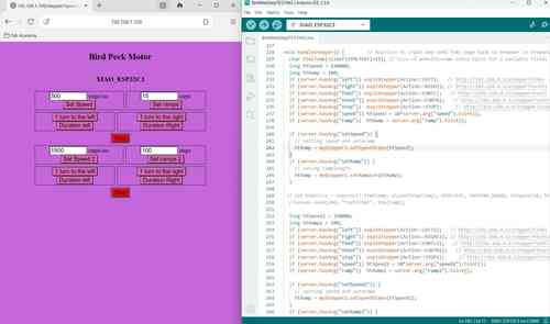
Making progress in the weeds of late night coding. At this point, I figured out how to add a second set of inputs for a second motor and separated it so that the top inputs apply to motor 1 and the bottom apply to motor 2. After a little more testing, I'll apply the same logic to create a third set of inputs for the final motor
Eventually, I figured out how to wire the motors and adapt the code to include all three steppers.
Using Web Server interface to operate all three motors!
Automation and Coding
Having the web server for controlling speed, acceleration, and duration of motor turn was great. Now, I had to learn how to automate the machine. Castor had the idea for the machine to play Mary Had a Little Lamb, which works as a three note song.
I wired a push button to one of the ESP-32 pins and tested different functions in the void loop to get precisely timed motor movement with each motor corresponding to a note in the song. By setting a high speed setting with low ramp length and adjusting the delay time in between motor movements, I found a sweet spot where there is no overlaps and the timing mirrors the song. I also found that when the code is running while button is pressed it blocks Web Server input functionality.
Three motors set up to Web Server and with button. Running motors to the tune of Mary Had a Little Lamb
Electronics Production and Wire Management
Circuit Board Production
Now that I've finally gotten a motor + code set up I can work with, I designed a circuit board for mounting the XIAO-ESP32 board and wiring with the 3 motor drivers. There was just enough pins to wire all three stepper motors and have I2C lines open just in case. (For this assignment, we'll just wire a button one of the I2C pins). I included headers for 5V power and for GND to have it and I included several headers for the 3.3V power connections since each motor will need access.
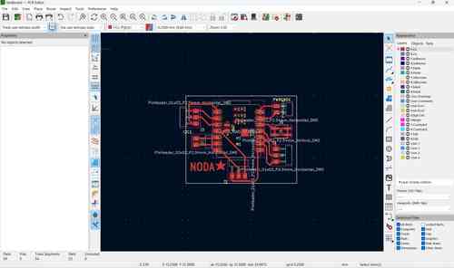
PCB design in KiCAD
After milling and soldering, I rewired the stepper motor drivers to my PCB.
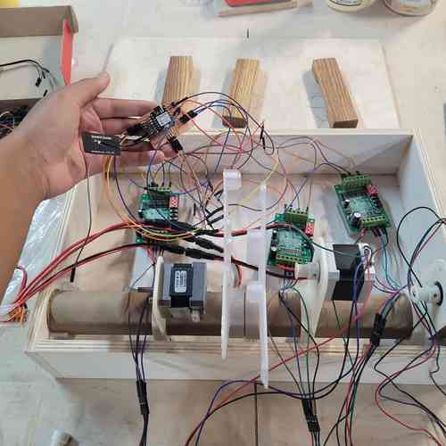
Making progress on wiring to PCB
Power We used the power supply equipment for motor driver power supply at 24V. We used a USB cable to power the XIAO ESP32-C3 board. To access these cords we needed to cut a hole to feed the wires through.
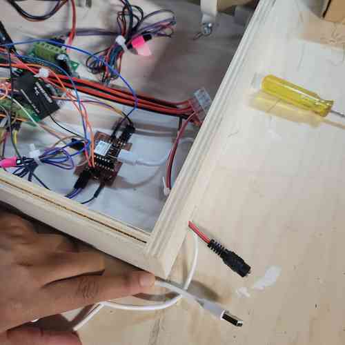
Creating an access hole for wires
Button We had this push button switch with screw terminals in the lab which is used in places like elevators. You can wire it by simply placing the wire underneath the screw before tightening it.
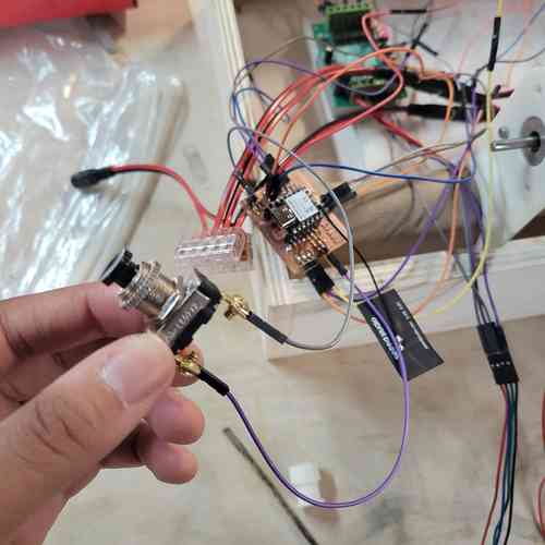
Fastronix Momentary Push Button Switch. Wired to the ground pins and pin D5 on the XIAO board.
Then we had to cut a hole for the button in our base board device and fix it in place so that users had easy access to press.
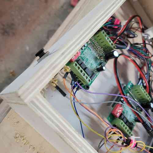
Button is securely in place!
After wiring everything up, all the motors ran smoothly on the first attempt. Eventually, I got some zip ties an tape for managing wires and fixtured the motors and PCB board into place.
A look under the hood. Tidied up the wires
Mechanical Design
Mechanical Design Learning in Fusion 360
Building on Castor's original design, I walked through some of the mechanical design steps in Fusion 360 with Will for learning purposes. I downloaded the Helical Gear Plus app from the app store to use in Fusion for generating gears. Notes below:
- After downloading the app, you can access it by Create >> Helical Gear+ and pro-tip check the "Preview" box to see changes as you adjust settings
- You typically don't dictate final size of gear directly. It's derived from number of teeth and size of teeth.
- You need to pick ratio for reliable meshing with gears. Best to work around certain ratio of pitch to circle diameter.
- In Helical Gear Menu, this is what "Module" refers to --> ratio of diameter to the number of teeth
- Pressure angle relates to pitch of the gear. Standard value s 20 degrees
- Backlash very slightly reduces size of the teeth so rather than being perfectly flush there is some room between them
- Addendum is how much the gear tooth extends above the pitch line whereas dedendum is how much the gear tooth extends below the pitch line. Typically better for dedendum to be a little larger so there's some clearance
- Pitch lines of meshing gears need to be tangent to each other
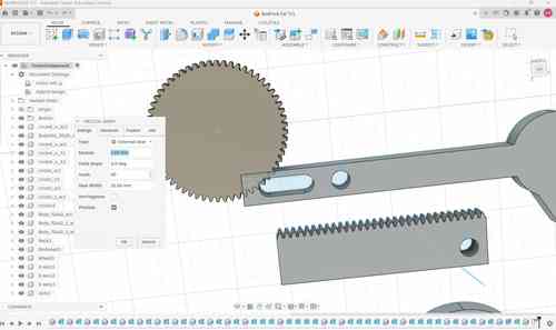
Creating gears on Fusion 360
For this design, I created one rack gear and one external gear with Module set at 1.00mm, Helix Angle set at 0.0 deg, and Gear Width at 10.00mm. Under advanced menu, I set the pressure angle at 20.0 deg, Backlash at 0.00 mm (could've set it to 0.10mm), Addendum set at 1.00 and Dedendum set at 1.25.
Building on Castor's original design, we needed to add a flat plane where gears could be fixtured and we needed to find a way for the rack gear to be "captured" so the it would stay in line. To capture we could add a slot to the rack gear and place two screws. Also needed to focus on spacing.
Aligned rack and external gear by their pitch line. Find midpoint of inner rectangle such that it aligns with the hole in the circle that's attached to the motor. Same thing with the bird striking piece slot needing to be aligned with the corresponding hole on the rack gear. I learned how to use align and move features and started to learn simulating joints.
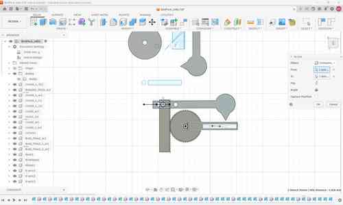
Aligning racks and gears in Fusion 360
Since time was getting the best of me, I didn't go further into design process on Fusion.
Mounting the Motors
Part of what I learned was how to take the operating motors and integrate them into the machine mechanism. As described during class, a mechanism is ""a device that transforms input forces and movement into a desired set of output forces and movement." So I'd need to think about joints, gears, bearings, etc. that would be needed to transform the motor's spinning into the bird striking the wooden block.
For mounting the motor, Will designed 3D printed mount to hold and mount the stepper motor which we assembled using 1/4-20 screws. Stepper motors also take M3 screws on their faces.
Mounts for stepper motor
Motors mounted on the cardboard tube
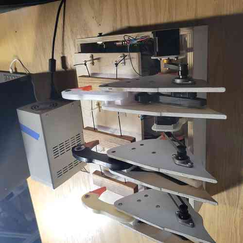
By attaching a gear to the motor and wrapping a pulley around that gear to another gear on a mounted ball bearing, this would allow our machine to run. Along the way, we had some design improvements to do which Will and Castor focused on. For example, the side of each bird pecker wasn't long enough for both ends of the ball bearing to be drilled in and this looseness caused some of the screws to fall out. So Castor designed a new and improved bird pecker side panel that looked more like a goose. This connects back to improved motor operation so the motor can run at high speeds without straining the mechanism.
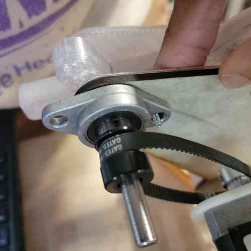
View of the mechanism for motor operation from earlier design
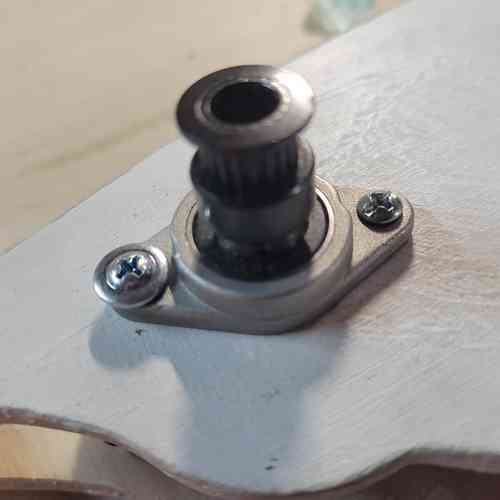
View of mechanism for motor operation from final design
Assembly
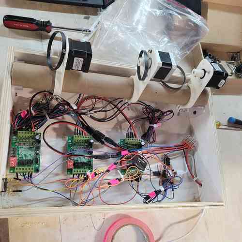
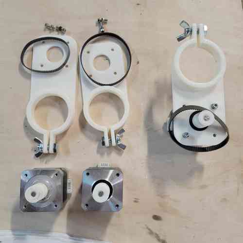
After we had all of our parts, we worked together on assembly.
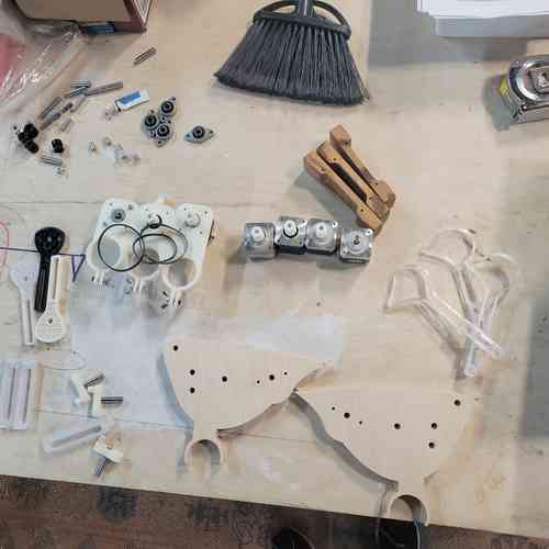
Layout of our parts for assembly
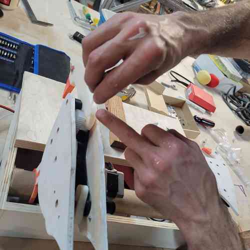
Troubleshooting
After our first round of assembly, for first attempt to run the machine only one of the birds worked smoothly. We decided to switch out the plastic gears on the stepper motors for metal ones and we greased the gears inside the bird with with silicone grease. We also just used the Web Server Interface to run the motors so the parts could wear in.
Adding in grease to the gears
After making these changes the bird ran much more smoothly.
Eventually, we finally got our machine to a working state.
Design Files
Find my design files for the week shared here