My Final Project : Music and Motion Player
Final Project Video:
Final Project Slide:
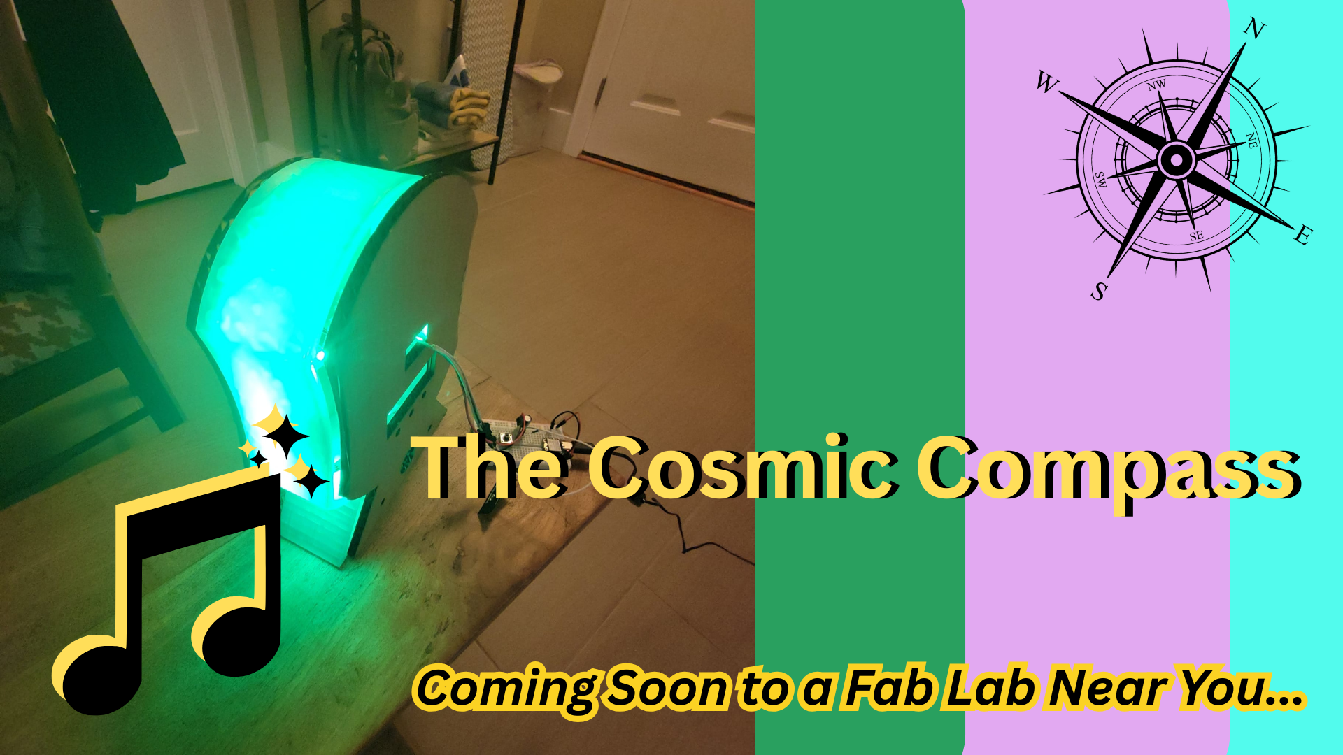
Table of Contents (click to jump to section)
🎵 Motion Music Player 🎵
For my final project, I made a motion-based music player. This interactive gadget will function as a device that plays music and responds motion to shuffle, play/pause, advance to next track, or go back to last track playing. It also detects inactivity and has a goes into power saving mode until activity is detected again. The track title display on an LCD screen with an OLED displaying user interface feedback and positive messages. It also toggles an LED light display. It is powered with an enclosed rechargeable battery system that integrates a charging hookup and power switch.
The device:
-
act as a motion-sensing MP3 player allowing for previous track, next track, and shuffle track features based on motion
-
displays song track title playing on Grove LCD screen
-
displays interface feedback on OLED screen to verify motion detected + meaningful quotes I like
-
houses audio amplification circuitry for boosting audio for speaker output
-
includes a 3 mode Neopixel light display operated by long-pressing the middle button
-
2nd Neopixel mode disabled motion input for audio playback so user can freely move device without changing song while light show corresponds to motion
-
includes a few buttons for play/pause, backward, and forward + LED mode changing
-
encloses a rechargeable battery system
Project Time Management
Spiral Development
Phase 1: Breadboard Prototype - demonstrate most basic electronics + code works
Phase 2: Custom PCB + Cardboard enclosure prototype - get a sense of integration and needs for tweaking physical design
Phase 3: Next rounds of streamlined design - complete set-up for charging circuit within cardboard prototype, test with final material
Phase 4: Further system integration with final materials
Quick links to Weekly Assignments that contributed directly to my final project development:
Relevant Weekly Assignments
Quick links to weekly assignments that contributed to my final project development:
-
Week 4: Embedded Programming: First learned how to wire and hook up push buttons and OLED screen displays to program using Arduino
-
Week 8: Electronics Production Learned PCB production integrating OLED screen and how to use oscilloscope for debugging
-
Week 9: Inputs First learned to use an accelerometer (not the same chip as my assignment but similar function)
-
Week 10: Outputs Learned about LM386 audio amplifier to use speaker outputs. I used a variation of this in my final project circuit
-
Week 16: Systems Integration This week got me together! How all the different pieces are integrated as a cohesively packaged system and not a big wire-y mess
-
Week 18: Project Development + Applications and Implications Created draft for final questions to be answered about final project
-
Week 19: Invention, Intellectual Property, and Income Project status check in and deciding licensing and final project dissemination
Work Plan
| Date | Focus | Tasks to Complete |
|---|---|---|
| April 30th | Final Project Planning | Finalize idea + sketch, plan out tasks, create systems diagram, order needed components, complete midterm review |
| May 6 | Breadboard Prototyping + CAD | Figure out electronics circuit; create design on Inkscape or Fusion 360, design and document systems integration |
| May 13th | Device Prototyping | Laser cut (or 3D print) draft design + (device holder if ahead) - incorporate with Wildcard week (meshtastic device??), design and 3D print enclosure for wiring |
| May 20th | Electronics Design + Production | Design custom PCB, mill, solder, and test |
| May 27th | Systems Integration and Testing | 3D print buttons, mounts, etc.; wire management; |
| June 3rd | Final Presentation | Finalize documentation, slide deck, and video; embellish / make pretty / make the playlist of my dreams |
Weekly Task Breakdown / Checklist
April 30th
Finalize idea + sketch
Create work plan
Sketch systems diagram
Place Digikey order for needed components
Complete Midterm Review - tasks completed
May 6th
Update electronics schematic
Complete initial electronics circuit testing
Document and design systems integration
Create initial design on Fusion 360 and export to Inkscape for laser cutting cardboard prototype
Test audio circuitry
May 13th
Finish next draft of 3D design on Fusion (esp the 3D printed internal layer)
3D print prototype and laser cut cardboard prototype of actual size of front and back panels
design enclosures for batteries
design PCBs for project on KiCad
develop most basic code that demonstrates all components working on breadboard
May 20th
Mill PCBs
solder and stuff PCBs with components
initial wire management placement (using crimped cables, etc)
test and debug most basic code on current circuit
May 27th
Mill next iteration of PCBs
solder and stuff updated PCBs with components
develop more advanced working code for updated project
3D print accessory pieces (button faces)
laser cut and engrave final panels on acrylic, mirrored acrylic, and walnut veneer
3D print final inner panel
mount, fixture, and secure all components inside >> pass shake/drop test
add decorative touches
June 3rd
Create final project slide deck
Create final project video
Finalize final project webpage
2D and 3D Design
Initial Sketches
Here's an initial sketch for the music player:
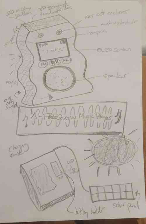
Music player and charger sketch
Updated Sketches
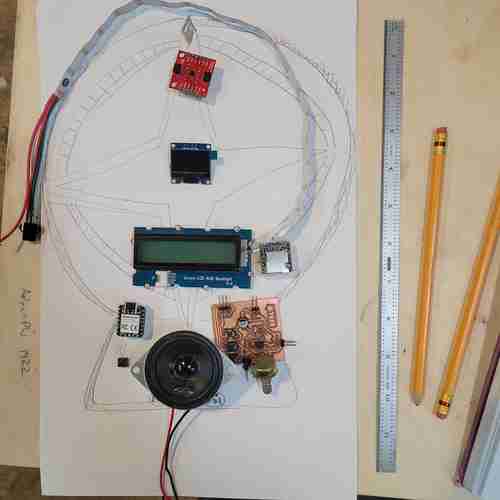
Updated sketch of my final project design with some of the components placed
Computer Aided Design
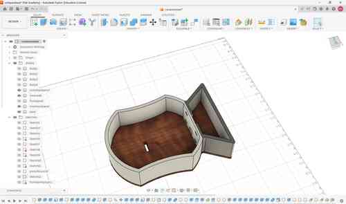
Here is an iteration of my prototype. After laser cutting and 3D printing, I have made tweaks to the design to fit with the components.
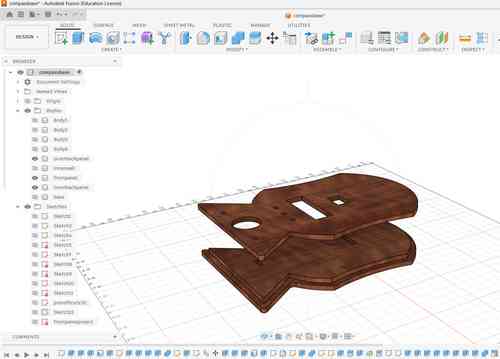
Another view of this prototype iteration of just the front and back panels. For the back panel, I am thinking to CNC mill this to take advantage of the 2.5D capabilities that can ensure a better fit.
Prototyping
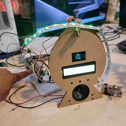
Breadboard testing early iteration of device. We've come a long way from here!
Here is the prototype of a second version of my design piecing together the cardboard laser cuts and 3D printed inner wall all together
To the right, I have printed the inner wall of the device. This took two separate print jobs because the size of the inner wall is bigger than the bed of our printer. Designed holes and extrusions that would allow for press-fit piecing together
Here I am testing how the Neopixel lighting looks through the 3D printed material with the second version of my design
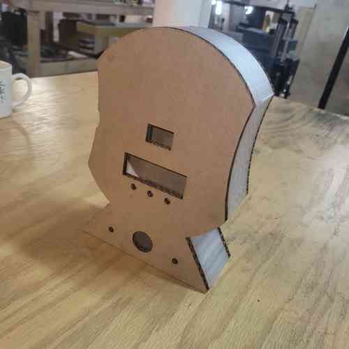
Another cardboard prototype iteration. Here, I have updated the design again to make it smaller after I pivoted from the compass idea so it didn't have to be quite so big
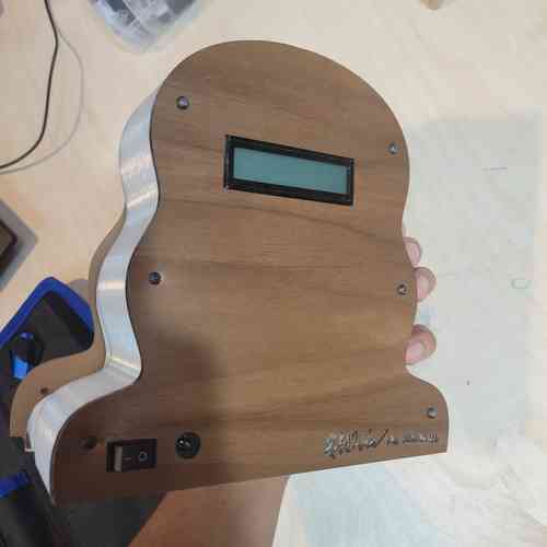
Eventually, I got to my final version of the design:
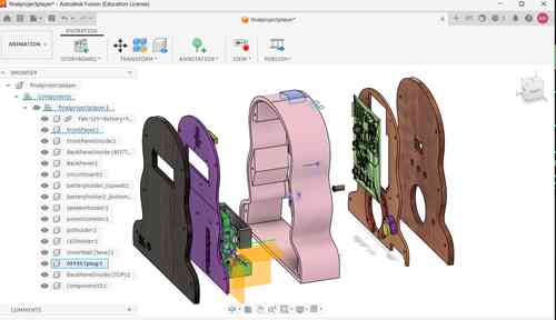
A view of my final design in Fusion 360 that incorporates systems integration planning and iterations
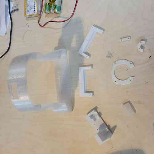
Additive Manufacturing
I will use 3D printing for the inner wall of the final project, for encasing for wiring/electronic components, and for button pads.
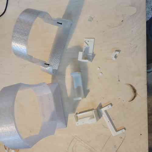
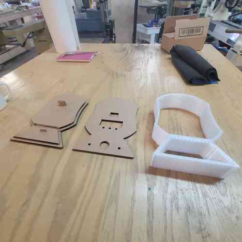
Here is an array of 3D prints made along the way for iterating
Inner Wall
Here is the final wall printed out along with the smaller prints
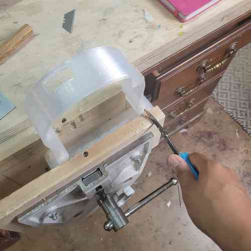
Here is my set up for chiseling out some of the more difficult supports The PLA adhered really tightly. After this, I sanded it to get a smooth surface finish
3-D print settings:
- Print settings: 0.55mm DRAFT (modified)
- Filament: Generic PLA
- Printer: Original Prusa i3 MK3S & MK3S + 0.8 nozzle
- Supports: Everywhere
- Infill: 15%
- Make sure "Generate support material" is checked
- Make sure Style is set to "snug"
- Make sure skirt loops set to 0 (since my print takes up the full bed space)
Estimated print time: 4 hours and 24 minutes
Mounts, Enclosures, Extra Bits
I used 3D printing for the mounts and enclosure to add secure placement of components. I used various printers and filament types based on what we had available. This included: potentiometer mount, the speaker enclosure, the strip for holding the LED strip in place, the top access piece for the SD card, and buttons. Had a couple iterations for some of these to get the fit just right in the tight spacing of my device. I also used a design by my instructor Will to hold the battery pack in place safely.
3-D print settings (Round 1):
- Print settings: 0.35mm STRUCTURAL (modified)
- Filament: Prusament ASA
- Printer: Original Prusa MINI & MINI + Input Shaper 0.6 nozzle
- Supports: For support enforcers only
- Infill: 20%
- Make sure to add brim and place objects close together so that the brims help hold each other down.
- For our specific printer, place bigger objects on the left side (side printer does better on)
Estimated print time Example: 2 hours 1 minute (for pot mount, speaker enclosure, battery mounts v1, and LED strip)
3-D print settings (Round 2):
- Print settings: 0.35mm STRUCTURAL (modified)
- Filament: Generic PETG
- Printer: Original Prusa MINI & MINI + Input Shaper 0.6 nozzle
- Supports: For support enforcers only
- Infill: 20%
- Make sure to add brim and place objects close together so that the brims help hold each other down.
- Change top interface layer to one (did this for the top piece plug)
Estimated print time Examples: (14 min for pot mount v2, 12 min for top piece plug, 1 hr 38 min for battery holder)
Subtractive Manufacturing
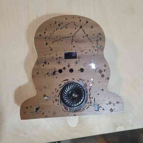
For my front and back panels of my project, I used our lab's laser cutter. For my final material used, I went with acrylic, mirrored acrylic, and walnut veneer.
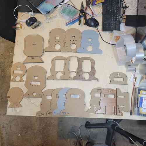
A progression of prototypes.
For exporting files to Inkscape, I had to add the shaper utilities app on Fusion 360's Autodesk because Inkscape was having a hard time recognizing the outer spline curve on a DXF file (reddit post explained). Then I could use this app under "Utilities" tab >> "Make" >> "Export to Origin." Then select the profile and you can then save that as an svg file.
Settings: For my settings, I referred back to our laser test cuts from Week 3's group work for the acrylic material. I will be using acrylic, mirrored acrylic, and a nice walnut veneer for adding an engraved wooden look to the final version. I chose these materials based on what we had most available at this point in the lab for laser cutting. At our lab, we have a 30 watt Epilog Helix laser cutter.
1/8'' Acrylic Cuts Settings
- Power: 95 (my global instructor advised not to use 100 to spare the wear on the laser cutter)
- Frequency: 5000
- Speed: 20 first pass, 10 second pass
- DPI: 600
1/8'' Mirrored Acrylic Cuts Settings
- Power: 95
- Frequency: 5000
- Speed: 10 first pass, 10 second pass
- DPI: 600
Walnut Veneer Engraving Settings
- Job Type: Raster
- Engrave Direction: Top-Down
- Speed: 20
- Power: 50
- Image Dithering: Floyd Steinberg
- DPI: 600
Walnut Veneer Cuts Settings
- Power: 22
- Frequency: 500
- Speed: 30
- DPI: 600
For the walnut veneer, I knew I wanted to engrave something on the top but was getting stuck. My classmate Castor surprised me with the perfect 2D design that I could use to cut and engrave on the walnut veneer and incorporates Aquarian astrological imagery.He also showed me how to sign my name on it which I had placed on the back. Shout out to Castor!
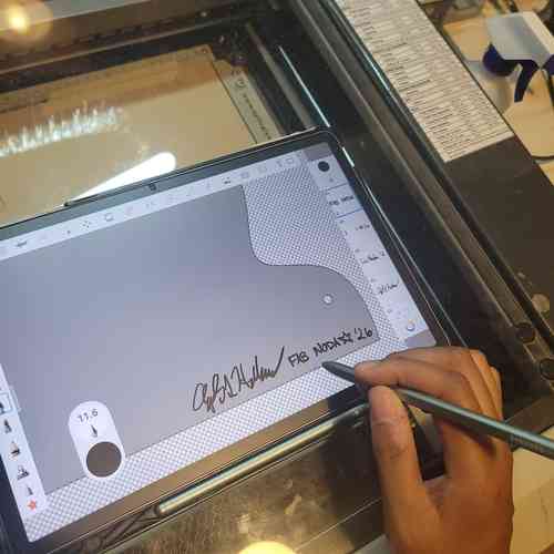
Adding my signature to the design with the help of Castor
I realized that I actually needed to cut that rather than engrave in order to see the mirror underneath. So after I did an engraving round, I then started randomly cutting away in Inkscape parts of the design before printing again so there would be a mixed of engraved bits and cut away bits.
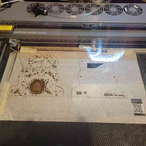
After cutting and engraving the walnut veneer
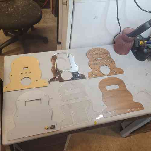
Here are my final laser cuts ready for assembly
Electronics Design and Production
I went through several challenging iterations of electronics design and production, but each iteration I emerged with a new and improved and better integrated design. For more on previous iterations and notes on components, see week 16 systems integration
Below are some example early schematic sketches:
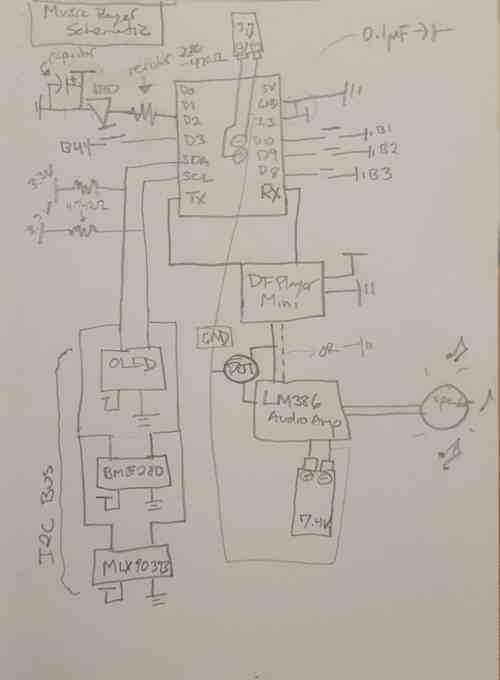
Sketch of schematic for the music player's electronic circuit
Updated sketch with systems integration in mind:
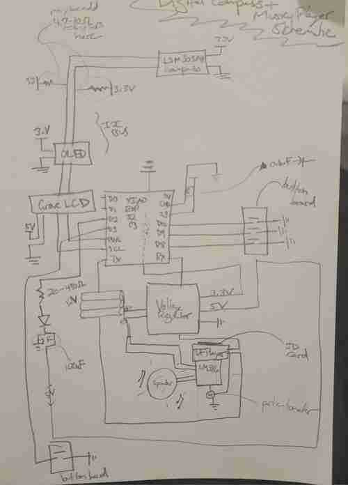
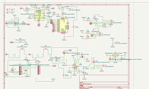
After some initial breadboard prototyping, I've updated the schematic for my project
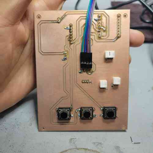
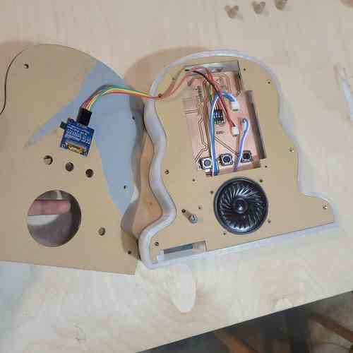
I have completed designs for each of the boards I am planning to use. I went through several iterations of this. I began with 6 interconnected boards but ultimately designed 1 board that directly wires to all components.
Final Board
Purpose: This final consolidated circuit board for my project houses the XIAO ESP32-C3 microcontroller which will control the input/output functions of the device. It includes an accelerometer chip circuit, and audio amplification and sound circuit, three buttons for interfacing, a pin-out for a Neopixel strip, a Grove-LCD, and an OLED screen. This board also includes circuitry for power supply management using a voltage regulators to convert 12V into 5 V. All electronics as integrated as possible! The only wiring needs will be to go to the potentiometer for audio control, the Neopixel strip, the Grove LCD, and (potentially) the OLED screen.
Notes:
-
KEY FINDING! The last version of this board did not work because I had wired an INT pin (pulled low) and BUSY pin to GPIO 9 and GPIO8. seeedstudio's webpage on XIAO ESP32 C3 specifies in the "Strapping Pins" section that GPIO2, GPIO8, AND GPIO9 are strapping pins and high / low configurations can stop it from running program. This is exactly what happended and why nothing would work (not even serial monitor) until cutting those traces. For this final version, I reconfigured my board so that only buttons are on those pins.
-
Since I will be supplying 5V power in via a battery, I use the VIN pin and MUST place a diode to ensure the flow of electricity stays in one direction. I used a Schottky SS34 Diode. See Seed studio's documentation here
-
I will now be using the ADXL343 Accelerometer chip for its motion detecting capabilities. I used the linked data sheet to figure out the circuitry. Some things I noted: tie CS pin high for I2C, tie ALT address low for I2C address at 0x53, must include external pull-up resistors on I2C lines (I did 4.7K Ohm), place decoupling capacitors close to VS/GND and VDDI/O+GND. I also wired INT1 and INT2 pins to use more of the chips capabilities.
-
The orientation of the DFPlayer Mini will now be placed with the SD card facing the top of the circuit board. I will design a hole in the top of the device with a removable plug for access
-
This board has placement for pull-up resistors for all I2C lines
-
I also had to learn how to reflow and take extra care to solder the tiny little ADXL343 chip. I was scared but Will walked my through a practice lesson and with flux paste, a magnifying screen, good chip engineering, and steady breathing I got it on the board even with my shaky hands 🙏🏾
Set-up for soldering the tiny ADXL343 chip on circuit board. My workflow was: 1. Turn chip pins facing up and place on double sided tap 2. tin soldering iron with solder 3. add dab of flux paste to pins 4. apply solder in thin layer across pins allowing it to flow where it wants to flow and make sure there is no bridging 5. clean chip with alcohol and brush 6. add dab of flux paste to the circuit board where the chip will be placed 7. place chip on circuit board in correct orientation (the circle in upper left hand corner is near pin 1) 8. push down on chip slightly to get it in a good and aligned place. then remove your hand 8. apply hot air via heat gun near the chip and watch for it to set into place
-
I learned how to mill double sided boards! This Bantam Tutorial explains the process. I needed to make sure to toggle "top" or "bottom" for which side was milling and be sure to flip the board the correct way which Bantam makes easy to follow. Also, when milling the first layer, don't do the edge cut just yet.
-
Also, since the accelerometer chip is tiny, I had to use the 0.005'' Engraving Bit which needs special attunement with settings. Summary of settings changes:
Thickness: measure double sided copper plate with tape adhere and film remove. My plate measured at 1.80 mm thick

Trace Depth: Go to advanced settings and click customize trace depths. After some test runs with the engraving bit, I wen with 0.07mm for the custom trace depth

Running the milling job with the engraving bit as if you're going to mill with a 1/64 in flat end and 1/32 inch flat end mill. Just cancel the job when you have completed the engraving bit portion. And reset normally settings (use default 0.20mm trace depth)
Components for soldering:
- XIAO ESP32 C3 board
- Schottky SS34 Diode
- ADXL343 Accelerometer
- NCP1117 SOT-223 voltage regulator
- 1206 SMD Resistors: 0 ohms (2 for jumpers), 4.7Ohms (6 for I2C pullups), 330 Ohm (1 for Neopixel), 10 Ohm (1 for audio amp), 1KOhm (1 for audio amp)
- 1206 SMD Capacitors: 1uF and 0.1uf (ADXL343 decoupling), 22uF (between 3V3 and GND), 0.1uF(=100 nanofarad; 1 for audio amp), 10uF (1 for audio amp), 0.05uF (=50 nanofarad; 1 for audio amp)
- polarized capacitors: 10uF (2 for voltage regulators, 2 for audio amp), 100uF (1 for neopixel), 250 uF (1 for audio amp), 470uF (1 for audio amp)
- Buttons (3)
- DFPlayer Mini
- LM386
- 4 socket JST connectors (2)
-
3 socket JST connectors (2)
-
OLED screen (connected via connectors)
- Potentiometer (connected via connectors)
- Grove-LCD (connected via connectors)
- Neopixel strip (connected via connectors)
Schematic for my main board v3
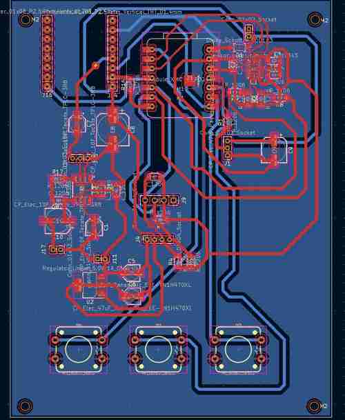
Layout for my main board v3 in Kicad
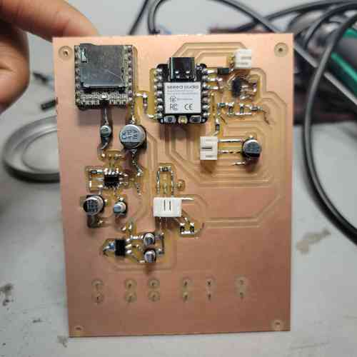
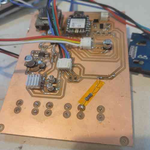
Here is the final board milled and stuffed!!
Annndd here's the back
Debugging
I had a lot of timely mishaps along the way. I made good use of my multimeter and our lab's oscilloscope to troubleshoot. A lot of issues were resolved by simply reflowing solder for joints I didn't get correctly in my late night soldering hours. For example, for one of my board iterations, the speaker kept making loud noises when power connected -- it started low then got louder and more and more high pitched. Tracing the power issue I found my onboard voltage regulator was fritzing out because I had a bad soldering job on one of my through holes.
One of my big discovering that my instructor found on seeed studio's XIAO ESP32-C3 page, was the[strapping pins] configurations of the ESP32C3s which was why XIAO would not run any programming despite power supply being confirmed as fine throughout the circuit. I had hooked interrupt pins (which pull low) of my accelerometer chip in such a way that caused a strapping combination of GPIO8 = 0 and GPIO=9 which the data sheet specifies as invalid. When those traces were cut the XIAO worked properly.
Another finding was that you need an external resistor for using GPIO8 on the XIAO so I soldered one on after milling and stuffing my final board in order to get one of my buttons to work properly.
A final tweak in the electronics production, my Neopixels were drawing a lot of current causing our power supply machine to dip down from 12V to 5 V to manage current (originally I had 20 on a strip). I switched it out for a small one that has more spacing between Neopixels and just uses 7 neopixels. It's not as bright but it didn't cause issues.
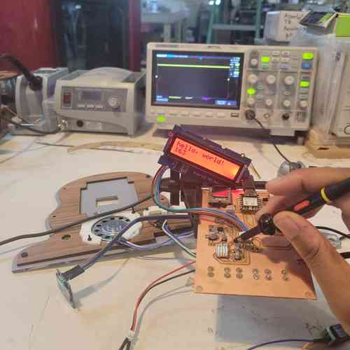
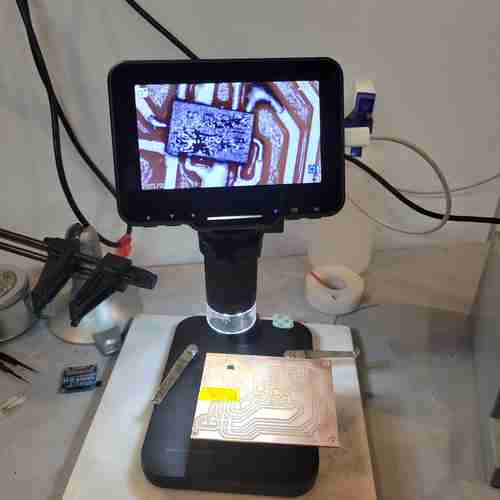
using Oscilloscope helped me to probe the board for debugging
Adding a pull-up resistor between one of button legs via through-hole and the 3.3V power line supplied by XIAO board.
Embedded Programming
My process My process for embedded programming was to compile piece by piece example/test code available from the libraries for the various components used and keep a log of working code. I would test to make sure each component worked. Then, to go a level up from there, I began combining code. For example, combine basic button press code with code for OLED screen + Grove LCD screen displays.This allowed me to identify on a basic level what works best for my microcontroller and set-up. Also, it was necessary for testing and debugging my circuit board.
Next I prompted Deepseek to provide code for the device (see consolidated superprompt in file below) which included my log of test working code (see file below for sources). Once I got a functional working code for the device, I then went in to make my own edits to personalize it. While I can understand basic code like operating one or two or three components at a time, integrating everything I had planned for this project involved much higher level code than I have had time to learn in my Fab Academy time. But I learned about the non-blocking architecture used which is something I've run into with timing delays when I write on my own. This generated code uses millis() command over delay() (which stops everything from operating for the duration of time specified) and the millis() essentially allows the code to keep running. Another more advanced feature was using one button to do multiple things -- the code specifies a short press as under 500ms and a long press as over 500 ms so basically if the button is pressed the program checks for how long and then either runs the play/pause function or the LED cycling function accordingly. The code also incorporates debouncing which we examined in Week 9 with the oscilloscope and button where we could see how in realities, there is bouncing instead of a perfect LOW - HIGH jump every time like when you click it kinda weird. Anyways, here's an example in the code that has these more advanced button handling:
// Middle button: short = play/pause, long = LED mode
if(buttonState[BTN_MIDDLE] == LOW && lastButtonState[BTN_MIDDLE] == HIGH) {
    if(now - lastDebounceTime[BTN_MIDDLE] > debounceDelay) {
    unsigned long pressStart = now;
    while(digitalRead(PIN_BUTTON_MIDDLE) == LOW && millis() - pressStart < 500) {
        delay(5);
    }
Find my final code used here
Find my log of working code compiled from various sources with my adaptations for this project here along with superprompt to Deepseek AI here
These files include my notes and sources.
Systems Integration and Packaging
As with every element, assembly and wiring took much more timing and consideration and troubleshooting than I thought.
In order to avoid having a mess of wires, I am using JST 2.00mm pitch connectors to group most of the wires together. I used 2.54mm pitch header strips for the OLED since its pins have different spacing. This has been integrated into my design on KiCad. I've also included M2 mounting holes so I can mount these boards in place within their enclosures or mounts. I will also add in threaded inserts for securing the panelling to the 3D printed inner wall, and (along with 3D prints) for securing several of the components in place such as the screens, speaker, batteries, and potentiometer.
Threaded Inserts
I placed threaded inserts for M2 and M3 screws for assembly. This allowed for integrating the 3D-printed inner wall with the laser cut panels and the components with their mounting pieces fixtured to these walls of the device.
Placing threaded insert on soldering iron. Shiny lip faces up. I set the heat at around 200°C and eventually when I got to the acrylic/mirrored acrylic material of my laser cut panels, I set the heat around 285°C
Placing in the threaded insert carefully with consistent pressure making sure to go in as straight as possible so that it is lush with surface
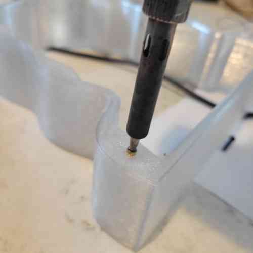
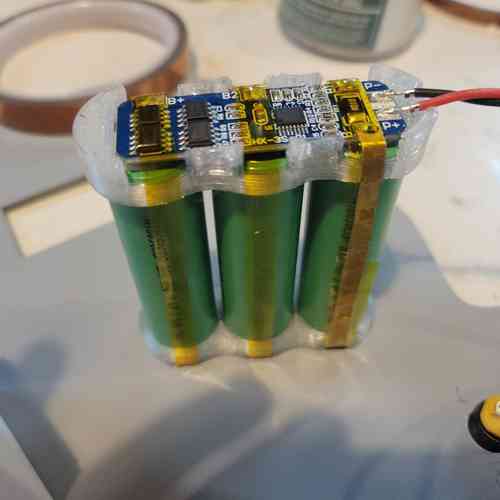
Battery Pack Assembly
For safety, my instructor Will walked me through step by step how to assemble and wire the three rechargeable lithium ion batteries in series to get ~12V. He also shared with me a small 3D printed design for sitting the batteries in place together with the battery module.
For this we used, thin sterling silver sheet metal strips available in the lab. We then used this 18650 Battery Protection Module (12V 10A) which allows for safe power management. With solder, I connected the silver strips from negative terminal of Battery 1 first and did battery to battery connects to wire the batteries in series.
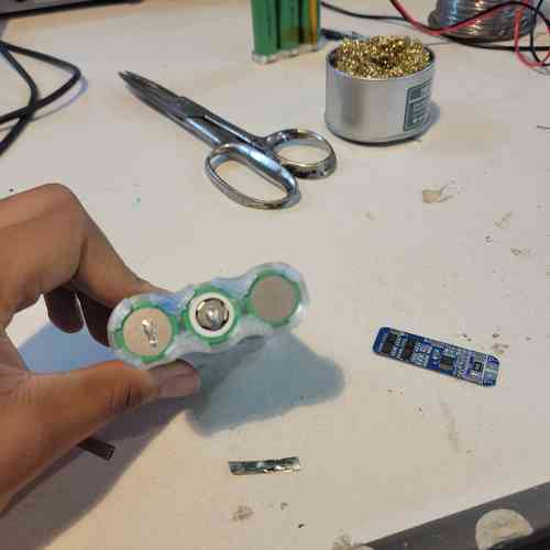
Then prepared strips going vertically along the side of cell 1 and cell 2 and then small taps sticking out that would fold up to be soldered onto the battery module.
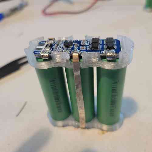
Had to be careful not to cause a short by touching strips or connecting in the wrong order (I did 😅 but it's a quick lesson to learn not to do it again)!
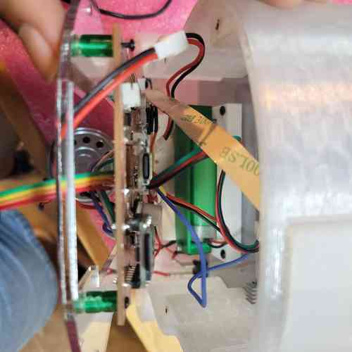
Assembly and Wiring
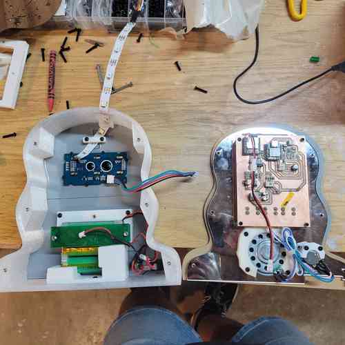
Beginning of assembly process. Speaker, potentiometers, batteries, and LED strip have mounts securing them in place. Wiring is kept as minimal as possible for this system. Zip ties used to tidy wiring between potentiometer and speaker.Everything folds nicely into place within the inner cavity of the device
Top view peak into electronics layout
Front view
Inner panel view
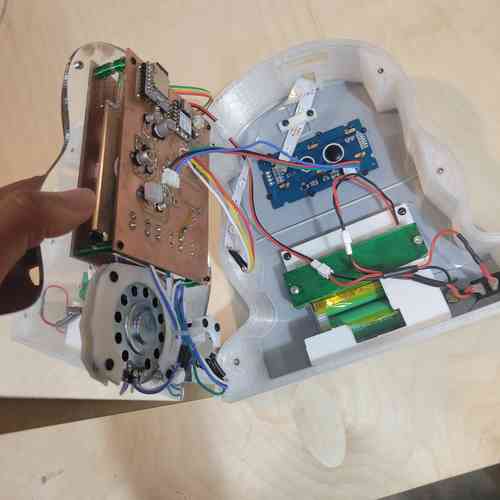
Under the hood of the electronics view
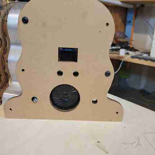
View of back panel
As you can see in my video, the assembly process involved proper configuration of wiring of components, using threaded inserts to fixture on mounts within and for screwing in panelling on front and back side.
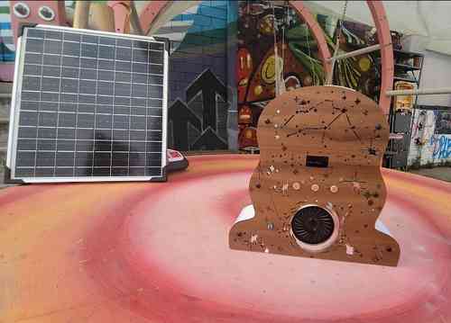
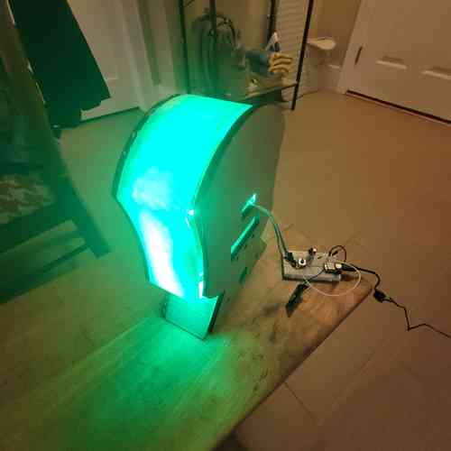
Final assembled music player out in the wild (at Fab NODA)
Bill of Materials
Here is my Bill of Materials for this final project electronics. Much of this we already had around the lab.
| Component | Info | Quantity | Price | Total |
|---|---|---|---|---|
| Neopixel Strip | 2541 | 7 (LEDS) | $0.47 | $3.29 ➡ (I used part of a strip) |
| Speaker | AS02808MR-R | 1 | $4.53 | $4.53 |
| JST Connector and Wire | YO-2503-2.0-Kit-HY | 14 | ~$0.37 | $5.18 |
| Accelerometer | ADXL343BCCZ | 1 | $3.69 | $3.69 |
| Linear Voltage Regulator 5V | NCV1117ST50T3G | 1 | $0.59 | $0.59 |
| Audio Amplifier | LM386M-1 | 1 | $1.33 | $1.33 |
| Potentiometer | TEKFA4076 | 1 | $1.99 | $1.99 |
| M2 Screws and Socket | 0P7L4P97S1Z95 | 32 | ~$0.09 | $2.88 |
| Threaded Inserts | B0FWRMXX4V | 32 | ~$0.09 | $2.88 |
| XIAO ESP32-C3 | 113991054 | 1 | $4.99 | $4.99 |
| 12V Rechargeable Battery | L111A26-3-2-2W | 1 | $27.64 | $27.64 |
| Battery Protection Module | 18650 | 1 | $3.90 | $3.90 |
| DFPlayer Mini | DFR0299 | 1 | $6.88 | $6.88 |
| 8G SD Card | U1 5Units | 1 | $8.38 | $8.38 |
| Button | FSM2JSMA | 3 | $0.28 | $0.84 |
| Rocker Switch | GRB112D802BB | 1 | $4.54 | $4.54 |
| Resistors 0603 | PHH5-KIT | 11 | ~$0.01 | $0.11 ➡ Breakdown of resistors used: 0Ω (2), 4.7Ω (6) 10Ω (1), 330Ω (1), 1kΩ (1) |
| Capacitor 1206 | 618202981142 | 13 | ~$0.01 | $0.13 ➡ Breakdown of capacitors used: 220nf (1),100nf (4), 10uF (1), 0.05uF (1), 10uF polarized(3), 250uF polarized (1), 22uF polarized (1), 470uF polarized (1) |
| Schottky Diode | SS34 | 1 | $0.04 | $0.04 |
| PLA Filament | Generic PLA | 1 large print | ~$2.00 | $2.00 |
| ASA Filament | Generic ASA | 1 medium print | ~$2.06 | $2.06 |
| PETG Filament | Generic PETG | 1 small print | ~$0.70 | $0.70 |
| Acrylic Sheet | 202038047 | 0.25 piece | $18.48 | $4.62 |
| Mirrored Acrylic Sheet | B0GSPRWDS6 | 3 sheets | $5.00 | $15.00 |
| Acrylic Sheet | 202038047 | ~2sqft | $2.89 | $5.78 |
| OLED Screen* | DM-OLED096-636 | 1 | $4.90 | $4.90 |
| Grove LCD* | 104030001 | 1 | $15.00 | $15.00 |
| Current Total | $133.87 |
Design Files
Here are my final design files:
Acknowledgements
Special thanks of course to my instructor Will for all the diligence, patience, enthusiasm that powered me through the challenges that came my way. His many sit-down sessions and guidance supported with my CAD design, putting together batteries and thinking through safe battery management in design, making the 3D button prints, and troubleshooting a thousand and one issues.
Thanks to my classmate Castor for the beautiful design for outer veneer panel and for always keeping things fun.
Note on Music Usage
Since this project will be archived online, I used free and open source audio for demonstrating the music playing functionality from pixabay's music archive. Their license summary here clarifies permission to use content freely. I will link to the songs I used that are featured in the final video below:
- "The Truth"
- "Water"by kontraa
- "Afrobeat Afro Beat Smooth Chill" by Sonican
- "Cozy Afrobeat - Lazy Trip"
- "Between Sky and Water"
- "Midnight Forest" by Syouki Takahashi
- "Sci-Fi Inspiring" by The Mountain
- "Simple Background"
Licensing
I share my final product under Creative Commons' CC BY-NC-SA 4.0 license which allows for freedom to share and adapt the material as long as there is attribution, noncommercial use, and same license usage for building on the material ("ShareAlike").
Final Project Questions
To recap and update the final project questions (drafted in Week 18):
What will it do?
See project overview above
Who's done what beforehand?
This project is far from an original idea. I am part of the growing body of hobbyist, makers, and people interested in DIY, simplified electronics like creating MP3 players so that you don't have to use your phone or big tech. Resources that I came across that sparked my interest and/or provided examples in this final iteration of the project include:
-
Kaled Souky's Retro-Style MP3 Player on Arduino documentation here
-
justwag's DIY Solar Powered Pocket Radio documented on instructables (I really want to dig more into solar-power next and integrating this into design)
-
Matt Keeter did a Fab Boombox.
What sources will you use?
There is lots of documentation on the various chips and modules my project uses. I first refer to data sheets and libraries
- XIAO ESP32-C3: data sheet
- ADXL343 Accelerometer: data sheet // library
- LM386 audio amplifier: data sheet
- AMS1117 voltage regulator: data sheet
- NCP1117 voltage regulator: data sheet
- Battery Protection Module: product page
- DFPlayer Mini: data sheet // library
- Neopixel strip: product page // library
I also have found a number of guides and blogs online for additional code and set up support:
- ADXL343 Accelerometer: Adafruit guide
- DFPlayer Mini: ZBotic Post; Homemade Circuit Project; Hackster post on use with ESP32
- Neopixel strip: esp32 tutorial page; Arduino blog post on toggle on/off switch
What will you design?
I will design:
-
an integrated main PCB with XIAO, accelerometer, power regulation, outputs, audio amplification circuit, and DFPlayer Mini
-
an enclosure for the device made from a combination of 3D printing and laser-cutting
-
3D printed mounts and enclosures
-
decorative engravings (with thanks to Castor!)
-
prompting for Deepseek AI code for programming + adapting to fit my project desires
What materials and components will be used? Where will come from? How much will they cost?
See Bill of Materials above.
What parts and systems will be made?
-
Front and back panels for the enclosure of the device made from acryllic and mirrored acryllic (was available in lab)
-
middle layer for the enclosure of the device made from 3D printing PLA filament
-
main board control system with XIAO, motion sensing ADXL343 accelerometer system, power management system, user interface system (buttons, LCD screen, OLED screen), audio board with audio amplifier system, and DFPlayer Mini hooked up to volume potentiometer and speaker
What processes will be used?
-
Computer Aided Design: Using Fusion 360 to do 3D modelling; using Inkscape for laser cutting and prototyping
-
Additive manufacturing: 3D printing
-
Subtractive manufacturing: laser cutting
-
Electronics Design and Production: designing PCBs in KiCAd, milling PCBs
-
Systems Integration: consolidating electronics design; using 3D printed enclosures and mounts, fixturing materials with press-fit with M2/M3 screws for added security, planning for user interface (ex. SD card access, on/off switch, displaying information on screens)
What questions were answered?
What about the design can be modified to improve the project now that I have decided not to use the magnotometer? --> I was able to make the design smaller and less tall which is more practical (the entire inner wall can fit on a 3D printer bed)
What are best practices for designing a device that can be both handheld and needs sturdiness to hold speaker and batteries that are a bit on the heavier and bulky side? --> adding in the curves on the side helped make it a bit more hand-able; using mounts for secure placement, the M2/M3 screws with threaded inserts helped keep everything secure; I ended up liking how the device can sit well and sturdily on its own
How do I best manage the timing and responsiveness of the code with interfacing the components at once? --> using millis() instead of delay() allows program to keep running and communicating with other input/outputs without stopping until end of delay
How sensitive or not sensitive will I need to adjust the accelerometer so that there are not false detections? --> this wasn't an issue; the only thing I didn't figure out here was how to distinguish the "Free Fall" detection from a "Shake" detection -- it wasn't key to my project so I didn't go deep here but the other functions of the accelerometer and its INT pins worked smoothly (once I got the chip properly situated on the board)
How will it be evaluated?
This project is fairly light-hearted and intended to add a fun motion-sensing element to a standard rechargeable music player. My primary motivations for the project are to personally learn from the process and have a functional device that will work in a year from now where hopefully I will get better and better in the realm of digital fabrication.
With that said, I'd consider success to be a music player device that reliably controls music outputs based on motion with an accompanying display that shows feedback of motion detection. I'd also want for the LED strip to be able to turn on and off with the button at the very least, but ideally it would correspond with the music.
Since shaking and motion is a part of the function, I will need to ensure that the device passes the "shake test" meaning secure and thoughtful integration and wire management.
Aesthetics is not my strongsuit so I won't evaluate myself on how pretty it looks but I do respect the need to go beyond a laser cut box type of design. I want to feel like I got to express some creativity and thoughtfulness in the final shape of it -- something that puts my own spin on a typical speaker/music player.
Though I am interested in playing more with sound, I am not evaluating myself as much by the actually quality of sound. But it should be decent.