Week 15: Interface and Application Programming
Our assignment:
Group Assignment:
1. compare as many tool options as possible
Individual Assignment:
1. write an application that interfaces a user with an input &/or output device that you made
Group Assignment
Find our group assignment documented here with pictures included and my documented contributions and learnings below.
p5.js
For the group assignment I decided to explore p5.js, a free, open-source JavaScript tool perfect for artists and those learning to code. I appreciated their emphasis on accessibility, inclusivity, and community.
You can set up coding environment either on the web or on your computer vs VS Code. I opted to use the Web Editor. NOTE: Firefox, Edge, Chrome, Safari are browsers that work. I had some issues trying to run on DuckDuckGo.
This software uses JavaScript programming language (hence ".js") which is great for making things pretty and interactive.
I walked through the tutorial and learned some of the basics for Javascript like how to change background size and color, how to draw shapes, how to start using user interface with mouse pressed inputs.
Next, I followed a tutorial for creating an interactive landscape. Learnings:
- all p5.js projects have its library and three files: index.html (sets up the webpage), sketch.js (sets the style of the webpage) and style.css (where you make changes to canvas)
- two main functions are setup() (like I'm used to in Arduino, this runs one time to set everything up before running the remaining functions) and draw() ( executes lines of code within curly brackets at 60 times per second until stop or noLoop() function)
- there's a cool feature for color where you can search for different colors within the web editor interface
- when drawing things, unless you specify values for thinks like fill color, stroke weight, stroke color, etc. it will just go by defaults
- you can add emojis! >> for example: text("🤠", 100, 370); this adds in an emoji with the corresponding X and Y (textSize(50) is used to change the size to say, 50)
- note about data types: some functions need arguments that are strings ("text") and some need arguments that are numbers (number)
- coding in the interactivity! for X and Y coordinates of things, rather than a number you can set it to "mouseX" and "mouseY" and it will adjust according to your pointer
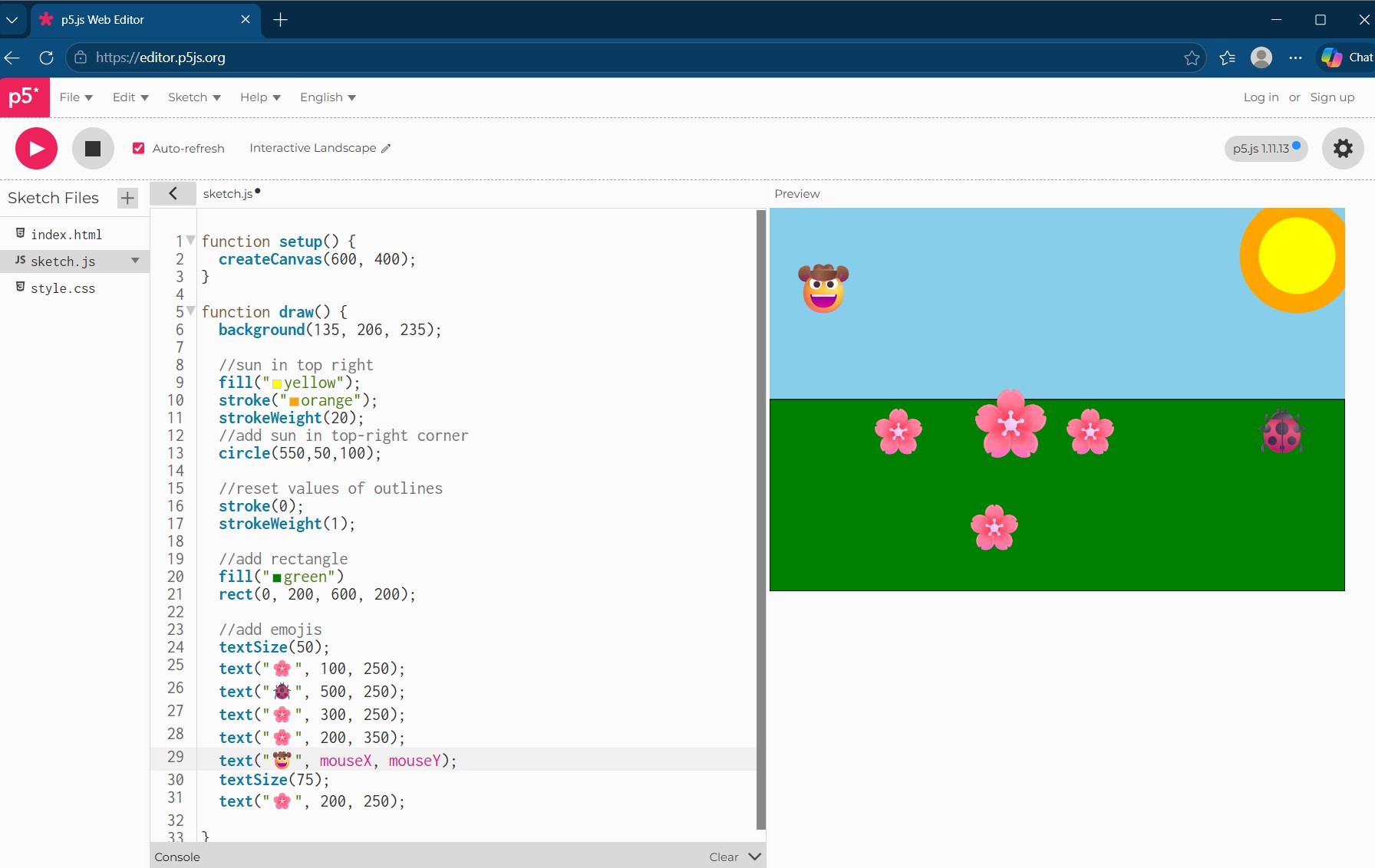
My beautiful landscape!
Now that I've got basic familiarity, I looked for ways to interact with a microcontroller board. This page on github provided a library to do this. I adapted code from this LED light example
First added in some extra LEDs and updated pins:
Code in Arduino
// Code from gohai's p5 webserial library on github: https://github.com/gohai/p5.webserial/tree/main
// angela adapted for Fab Academy 2026

//defining LED pins
#define LED_PIN D2
#define LED2_PIN D3
#define LED3_PIN D4

void setup() {
Serial.begin(57600);

//set LED pins as outputs
pinMode(LED_PIN, OUTPUT);
pinMode(LED2_PIN, OUTPUT);
pinMode(LED3_PIN, OUTPUT);
}

void loop() {
if (Serial.available() > 0) {
    String line = Serial.readStringUntil('\n');
    line.trim();  // get rid of unwanted characters
        if (line == "1") {
        digitalWrite(LED_PIN, HIGH); // turns LEDs on
    digitalWrite(LED2_PIN, HIGH);
    digitalWrite(LED3_PIN, HIGH);
    } else if (line == "0") {
    digitalWrite(LED_PIN, LOW);  // turns LEDs off
    digitalWrite(LED2_PIN, LOW);
    digitalWrite(LED3_PIN, LOW);
    }
}
}
Then I had to carefully look through documentation to figure out how to adapt the code for it to work with my XIAO ESP 32 C3 microcontroller and the port it is in. This meant I needed to specify "COM14" as my port since thats where my microcontroller is plugged in (working with Processing earlier helped me figure this out). Also, since I'm not using an Arduino board I took out the part of code that looks for that board specifically. And changed some of the language. My main and most time consuming mistake: trying to use DuckDuckGo 🫠 Once I ran the code with its adjustments in a compatible browser it worked!
Code for p5.js Web Editor
// code from gohai's p5 webserial library on github: https://github.com/gohai/p5.webserial/tree/main
//angela adapted for Fab Academy 2026

let port;
let connectBtn;
let ledOn = false;

function setup() {
createCanvas(400, 400);

port = createSerial();
connectBtn = createButton("Connect to XIAO");
connectBtn.mousePressed(connectBtnClick);

// in setup, we can open ports we have used previously
// without user interaction
let usedPorts = usedSerialPorts();
if (usedPorts.length > 0) {
    port.open("COM14", 57600);
    connectBtn.html("Disconnect");
    //connectBtn.hide();
}
}

function draw() {
background(255);

if (ledOn) {
    fill(255, 0, 0);
} else {
    noFill();
}
circle(width / 2, height / 2, 200);
}

function mouseClicked() {
if (ledOn) {
    // it's on, turn it off
    ledOn = false;
    port.println("0");
} else {
    // it's off, turn it on
    ledOn = true;
    port.println("1");
}
}

function connectBtnClick() {
if (connectBtn.html() != "Disconnect") {
    port.open(57600);
    connectBtn.html("Disconnect");
    //connectBtn.hide();
} else {
    port.close();
    connectBtn.html("Connect to XIAO");
}
}
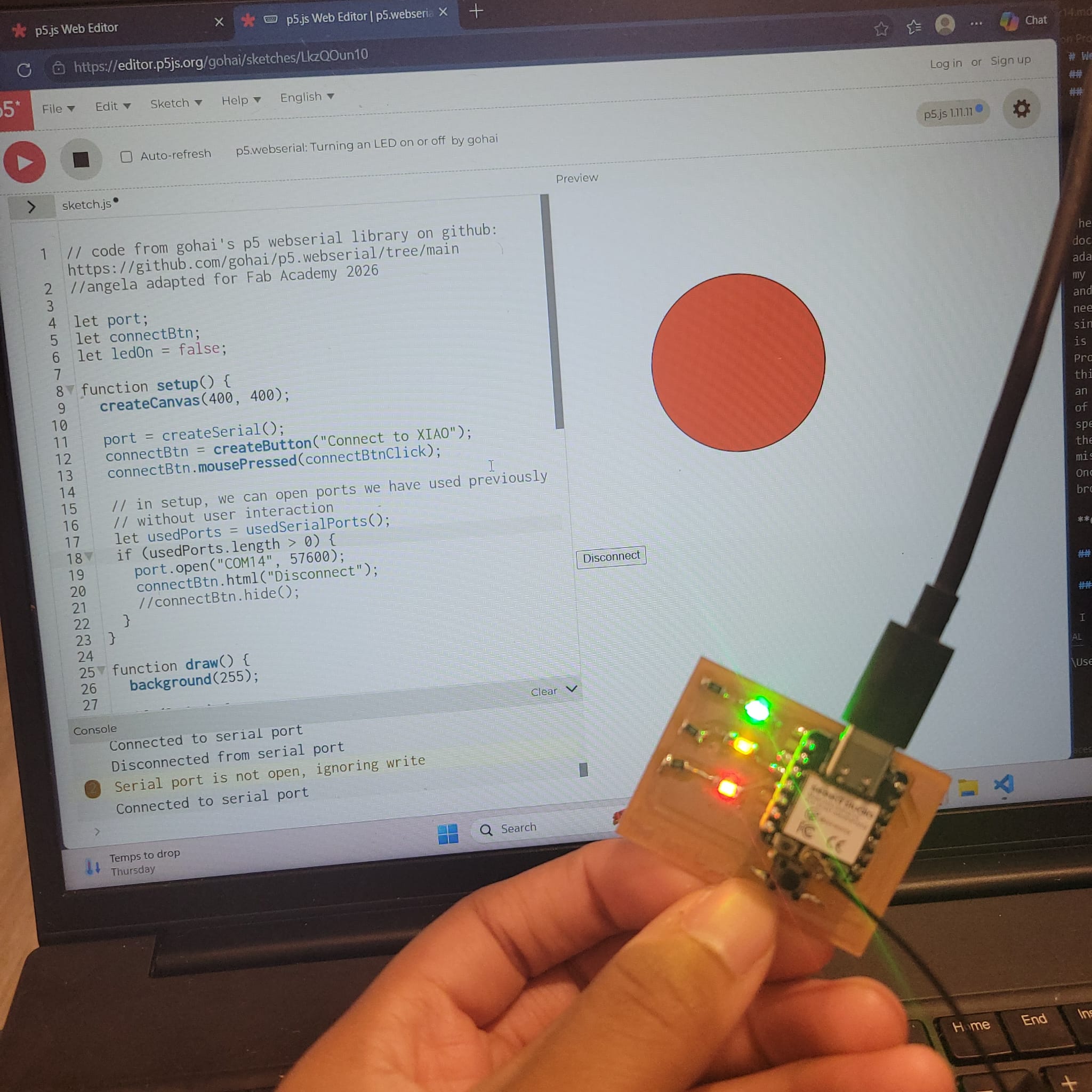
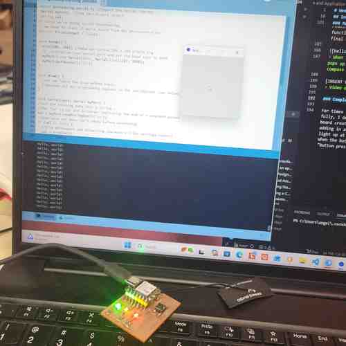
When I connect the XIAO to the web server I can then use the button function to turn the LEDs on the board on and off
Here's a video of using this
Overall, p5.js is a wonderful resource and very friendly to use for beginners like me. It uses JavaScript and is similar to Processing (which I used for my individual assignment). I appreciated how you can share a URL to open up and share code and how its optimized for web use.
Individual Assignment
Getting Started with Processing
I began by downloading Processing and running through a series of tutorials available on their website to get familiar with the interface and using Java.
Some learnings to note:
- a static sketch is a program written as a list of statement and performs tasks without interaction (ex. draw a line)
- an interactive program is one that has built-in functions (ex. setup() and draw()) that allow for interaction
- Processing has a ton of libraries and tutorials. Some fun sound related ones are the example Sound library
- Check out Make: Getting Started with Processing resource when I have more time
Connecting Arduino to Processing
Next I followed this Sparkfun tutorial shared in the Fab Academy resources to figure out how to get Arduino and Processing to communicate together.
After writing and saving test code in Arduino, I opened up Processing and went to Sketch >> Import Library >> Serial and then added the test code provided by the tutorial. Note: my microcontroller was plugged into COM10 port. Using the number 0 in the corresponding place in code worked for me to detect this port. Also, I had to make sure that I had closed out Arduino IDE so that the port wasn't busy.
Code Used in Arduino
// Code created using Sparkfun tutorial on connecting Arduino with Processing: https://learn.sparkfun.com/tutorials/connecting-arduino-to-processing
// for Angela Henderson Fab Academy 2026 assignment

void setup() {

//initialize serial communications at a 9600 baud rate
Serial.begin(9600);

}

void loop() {
// send 'Hello, world!' over the serial port
Serial.println("Hello, world!");
//wait 100 milliseconds
delay(100);

}
Code Used in Processing
// Code from above tutorial used in Processing
Serial myPort; // Create object from Serial class
String val; //Data received from serial port

void setup()
{
// open whatever port is the one you're using
String portName = Serial.list()[0]; // change number in [ ] to match the port
myPort = new Serial(this, portName, 9600);
}

void draw()
{
if ( myPort.available() > 0)
{ // If data is available
val = myPort.readStringUntil('\n'); // read it and store it in val
}
println(val); // print it out in the console
}
Hello, world testing sending data from Arduino to Processing
Next I tried the reverse: sending data from Processing to Arduino, again following the tutorial. The code sends a '1' whenever there is a mouse click in the processing window and prints that on the console (or zero with no click). Since I have a Xiao board and not an Arduino board as the tutorial is made for, I wired up an LED to the D7 pin of the XIAO board including a 330Ohm resistor and slightly altered the Arduino code to use that as an output pin. So, when I click on the interface in Processing, it should light up the LED.
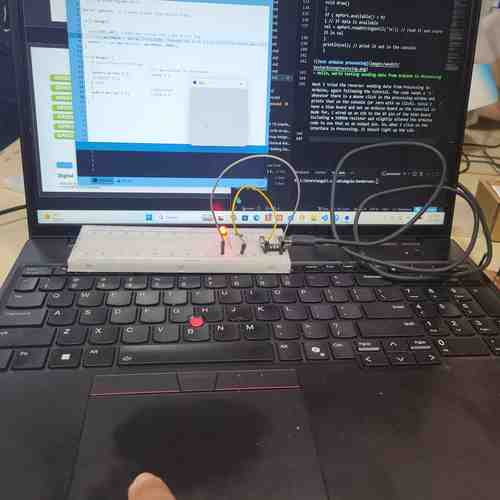
Clicking on the interface lights up the LED
Video of clicking the interface to turn on LED light
Next, I tried "shaking hands" i.e. allowing data to flow both ways between Arduino and Processing. Wrote up code in Arduino (Note! I had to move up the establishContact function to go right after void setup function in order for it to work).
Video of data flowing both ways. The microcontroller is sending the Hello, world! data and the click in Processing interface controls the light
Making a Compass with Magnetometer
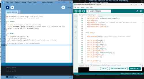
Since I wanted to use a magnetometer in my final project, I pulled out a SparkFun Triple Axis Magnetometer MLX90393. Following the hookup guide, I uploaded the example code (reproduced below) in Arduino to test the sensor:
/*
MLX90393 Magnetometer Example Code
By: Nathan Seidle
SparkFun Electronics
Date: February 6th, 2017
License: This code is public domain but you buy me a beer if you use this and we meet someday (Beerware license).

Read the mag fields on three XYZ axis

Hardware Connections (Breakout board to Arduino):
3.3V = 3.3V
GND = GND
SDA = A4
SCL = A5

Serial.print it out at 9600 baud to serial monitor.
*/

#include <Wire.h>
#include <MLX90393.h> //From https://github.com/tedyapo/arduino-MLX90393 by Theodore Yapo

MLX90393 mlx;
MLX90393::txyz data; //Create a structure, called data, of four floats (t, x, y, and z)

void setup()
{
Serial.begin(9600);
Serial.println("MLX90393 Read Example");
Wire.begin();
mlx.begin(); //Assumes I2C jumpers are GND. No DRDY pin used.
mlx.setOverSampling(0);
mlx.setDigitalFiltering(0);
}

void loop()
{
mlx.readData(data); //Read the values from the sensor

Serial.print("magX[");
Serial.print(data.x);
Serial.print("] magY[");
Serial.print(data.y);
Serial.print("] magZ[");
Serial.print(data.z);
Serial.print("] temperature(C)[");
Serial.print(data.t);
Serial.print("]");

Serial.println();

delay(1000);
}
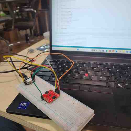
Breadboard test of magnetometer. I discovered this board also has a temperature sensor too!
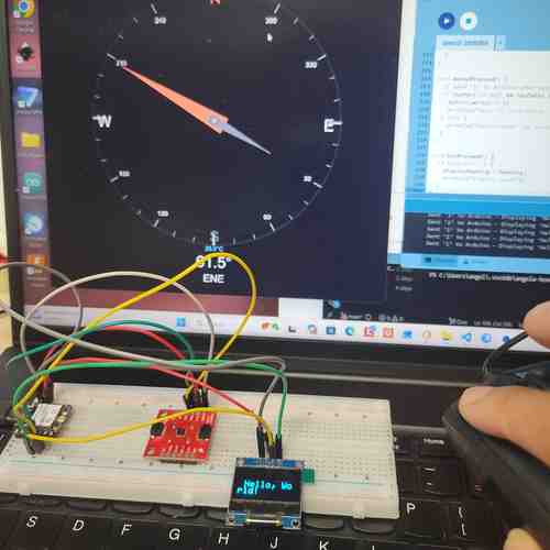
Now that I got that test code working and verified the magnetometer worked, I now needed code for Arduino IDE and Processing IDE that would display a compass that moves along according to the sensor input data. For this, I prompted Deepseek which provided baseline code for me to work with: "I have an XIAO ESP32-C3 board connected to a SparkFun MLX90393 magnetometer. I need Arduino code that reads the sensor, calculates the heading angle (0-360°), sends it over Serial, and Processing code that displays a rotating compass needle. The sensor is detected at I2C address 0x0C.". Basically, this code works to calculate heading angle based on sensor data and that number is what is sent to Processing. I spent a while debugging and trying to figure out best method for calibrating the magnetometer since at first it wasn't giving a good range. Eventually, I got the code to a good working place by auto-calibrating the magnetometer(see design files below for code).
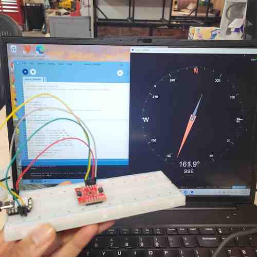
Using the magnetometer as a compass!
Here's a video of the magnetometer working as a compass
While I had this set up, I decided to try wiring up an OLED screen and getting a compass to display on that
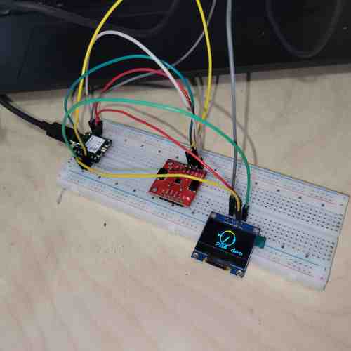
Compass on OLED screen -- it's a little squished but does correspond to change in direction
Since the magnetometer has a temperature sensor onboard, I decided to update the original code (with a Deepseek prompt: "Update the existing Arduino and Processing code to also read and display the temperature from the MLX90393 sensor. The data format should be "heading,temperature" over Serial. In Processing, add a temperature gauge bar that changes color (blue for cold, orange for hot) and shows the temperature in Celsius.") to just use that functionality and display on the screen. This was simple enough.
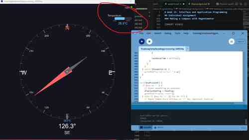
Updated display to include temperature
Next, I decided to challenge myself to figure out on my own how I could get the application to communicate with the microcontroller board. I figured I'd refer to the tutorial code for switching on a LED light. My guess is that if I just change the code in Arduino to configure an OLED screen and include code for displaying "Hello, world!" on the OLED screen instead of code for turning the light on then that should work...I'm not sure how it will interfere with the compass heading code.
After correcting for typos, missed semicolons, and missed brackets, I had my first attempt uploaded.
Next, I headed to Processing to add in the code there. On my first try, I got an error message "Duplicate method serialEvent(Serial) because I had added in a function in the code "serialEvent" but it had already been used earlier. So I tried just inserting the content of that function within the already existing one. Next I got an error that the "variable 'val' does not exist." I realized I forgot to include this in the beginning of the sketch. Then the sketch uploaded but the compass interface just showed no data connection. I tried consolidating boolean operation to remove repetitiveness. I spent a while messing around and then prompted Deepseek again to help find errors. I did this by sharing the code I had and prompting "I am updating the code so that if I click it will write "Hello, world!" on an OLED screen hooked up to the microcontroller. However with the code in Processing I am getting a message for "No data connection." Can you explain any errors detected in the code?" It looks like I had duplicated processes for reading serial data. It also included a mousePressed() function for sending the '1' to Arduino when I click. The final code generated is included in the design files.
When I click on the screen the message, "Hello, world!" pops up on my OLED screen. Otherwise, it displays a compass visual
Video of compass working
Completing the Assignment
For times sake and for the sake of writing my own code fully, I decided to next pull out my old stoplight LED board created. I updated the Sparkfun tutorial code by adding in all three LEDs on the board so that they'll all light up at the click. I also added in a button so that when the button is clicked it will send the message "Button pressed!" to the Serial monitor in Processing.
When I click on the box in the application interface, all three LEDs light up on my board. When I click again, they turn off.
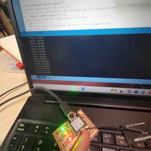
When I press the button on my board, the message "Button pressed!" shows up in the console of Processing
Video of using application for communicating with embedded microcontroller board, using input button device and output LEDs
Design Files
Find Design Files (code) for this week linked here