Week 16: System Integration
Our assignment:
Individual Assignment: 1. design and document the system integration for your final projects
See my final project page for an overview of systems integration documentation and more detailed design and documentation below.
Revisions - Ready for Review!
Adding in some revisions to provide more design and details of systems integration. As a part of the process, I have iterated and adapted the project. I have consolidated my PCBs, added design features like mount holes/insets for secure and tidy board placement, incorporated more design elements based on electronic hardware needs, and planned for tidy, secure wire management. I began with the intention of focusing on the compass breakout but in the process became more inspired to work with an accelerometer and motion.
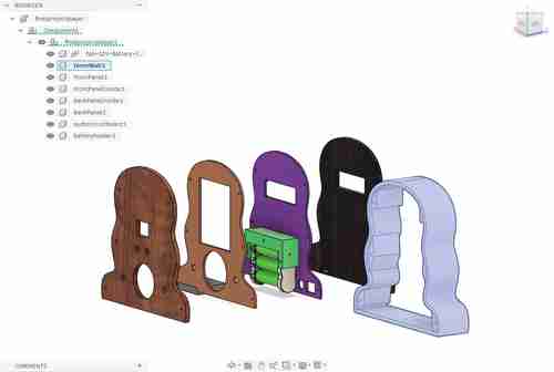
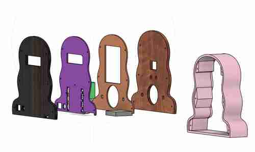
Electronic Boards
I have completed designs for each of the boards I am planning to use. I went through several iterations of this. I began with 6 interconnected boards but ultimately designed 1 board that directly wires to all components.
Final Board
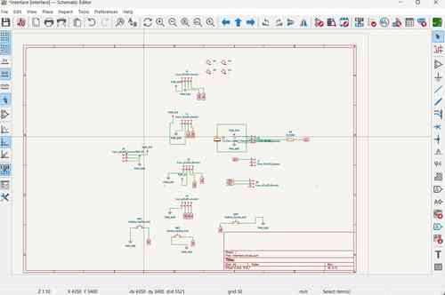
Purpose: This final consolidated board houses the XIAO ESP32-C3 microcontroller which will control the input/output functions of the device. It includes an accelerometer chip circuit, and audio amplification and sound circuit, three buttons for interfacing, a pinout for a Neopixel strip, a Grove-LCD, and an OLED screen. This board also includes circuitry for power supply management using a voltage regulators to convert 12V into 5 V. All electronics as integrated as possible! The only wiring needs will be to go to the potentiometer for audio control, the Neopixel strip, the Grove LCD, and (potentially) the OLED screen.
Notes: (more notes below on previous versions)
-
KEY FINDING! The last version of this board did not work because I had wired an INT pin (pulled low) and BUSY pin to GPIO 9 and GPIO8. seeedstudio's webpage on XIAO ESP32 C3 specifies in the "Strapping Pins" section that GPIO2, GPIO8, AND GPIO9 are strapping pins and high / low configurations can stop it from running program. This is exactly what happended and why nothing would work (not even serial monitor) until cutting those traces. For this final version, I reconfigured my board so that only buttons are on those pins.
-
Since I will be supplying 5V power in via a battery, I use the VIN pin and MUST place a diode to ensure the flow of electricity stays in one direction. I used a Schottky SS34 Diode. See Seed studio's documentation here
-
I will now be using the ADXL343 Accelerometer chip for its motion detecting capabilities. I used the linked data sheet to figure out the circuitry. Some things I noted: tie CS pin high for I2C, tie ALT address low for I2C address at 0x53, must include external pull-up resistors on I2C lines (I did 4.7K Ohm), place decoupling capacitors close to VS/GND and VDDI/O+GND. I also wired INT1 and INT2 pins to use more of the chips capabilities.
-
The orientation of the DFPlayer Mini will now be placed with the SD card facing the top of the circuit board. I will design a hole in the top of the device with a removable plug for access
Components for soldering:
- XIAO ESP32 C3 board
- Schottky SS34 Diode
- ADXL343 Accelerometer
- NCP1117 SOT-223 voltage regulator
- 1206 SMD Resistors: 0 ohms (2 for jumpers), 4.7Ohms (6 for I2C pullups), 330 Ohm (1 for Neopixel), 10 Ohm (1 for audio amp), 1KOhm (1 for audio amp)
- 1206 SMD Capacitors: 1uF and 0.1uf (ADXL343 decoupling), 22uF (between 3V3 and GND), 0.1uF(=100 nanofarad; 1 for audio amp), 10uF (1 for audio amp), 0.05uF (=50 nanofarad; 1 for audio amp)
- polarized capacitors: 10uF (2 for voltage regulators, 2 for audio amp), 100uF (1 for neopixel), 250 uF (1 for audio amp), 470uF (1 for audio amp)
- Buttons (3)
- DFPlayer Mini
- LM386
- 4 socket JST connectors (2)
-
3 socket JST connectors (2)
-
OLED screen (connected via connectors)
- Potentiometer (connected via connectors)
- Grove-LCD (connected via connectors)
- Neopixel strip (connected via connectors)
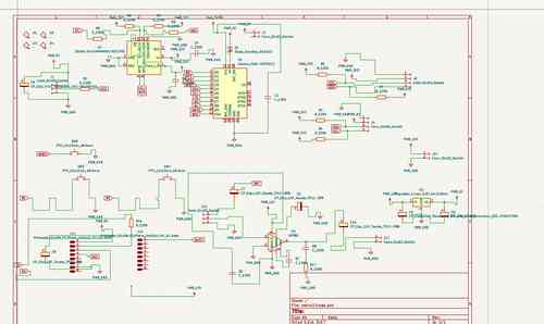
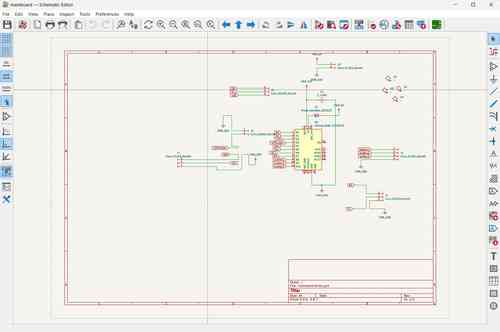
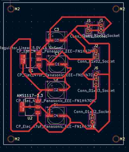
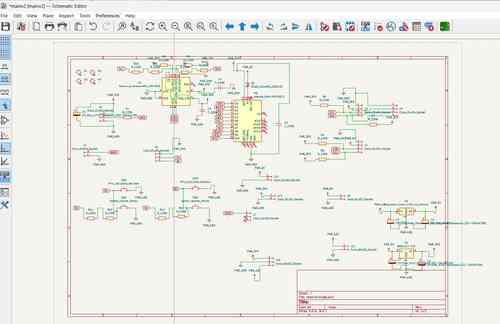
Schematic for my main board v3
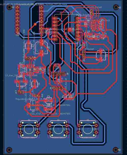
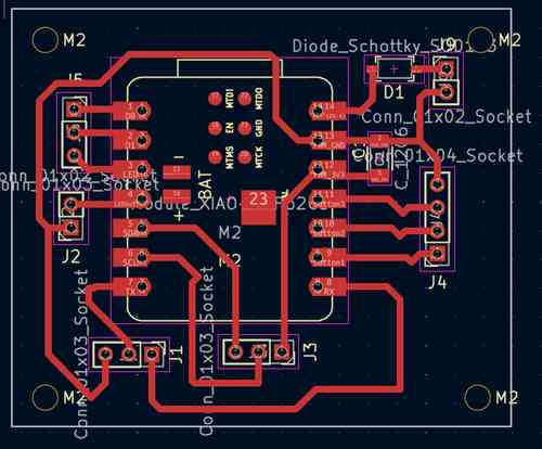
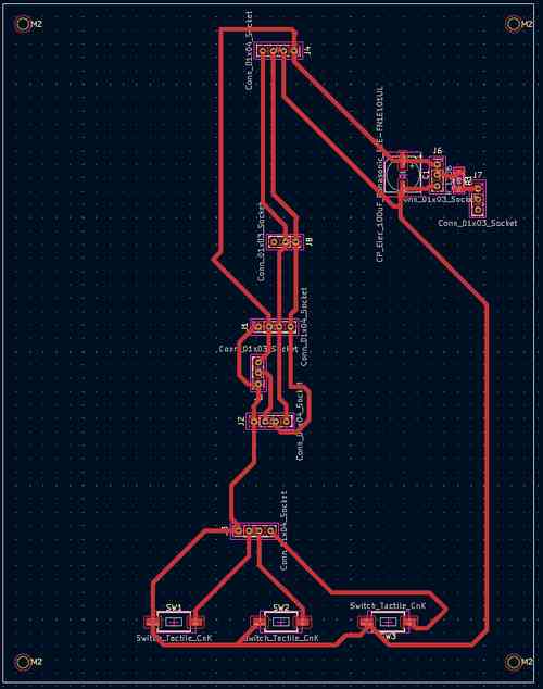
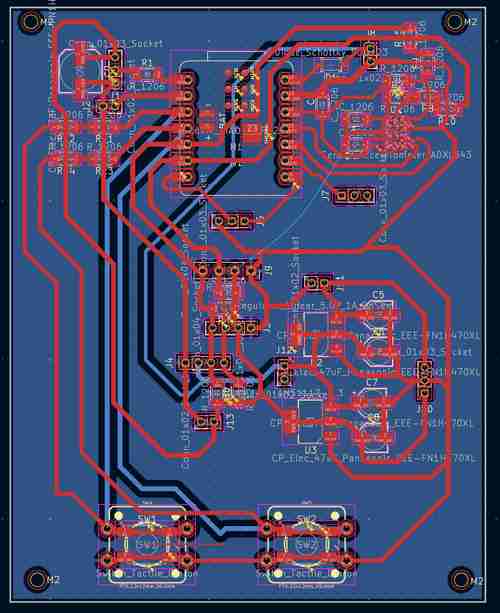
Layout for my main board v3 in Kicad
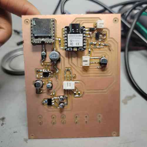
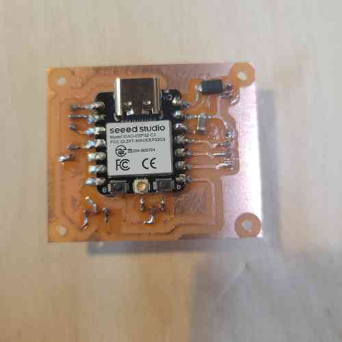
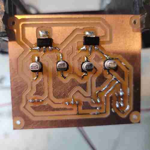
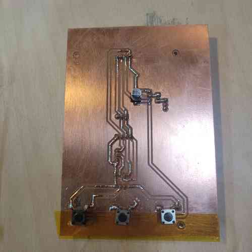
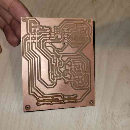
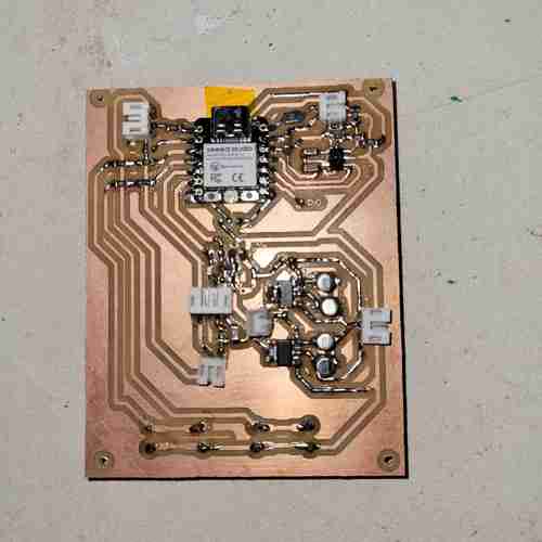
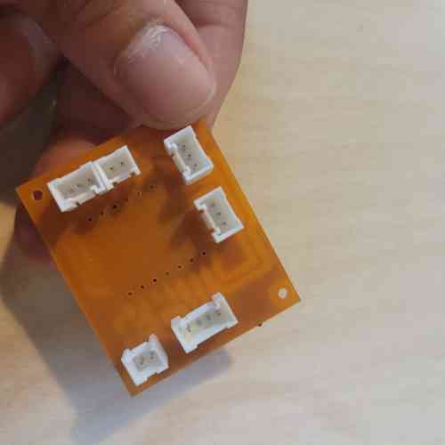
Here is the final board milled and stuffed!!
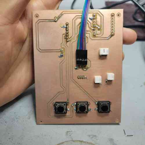
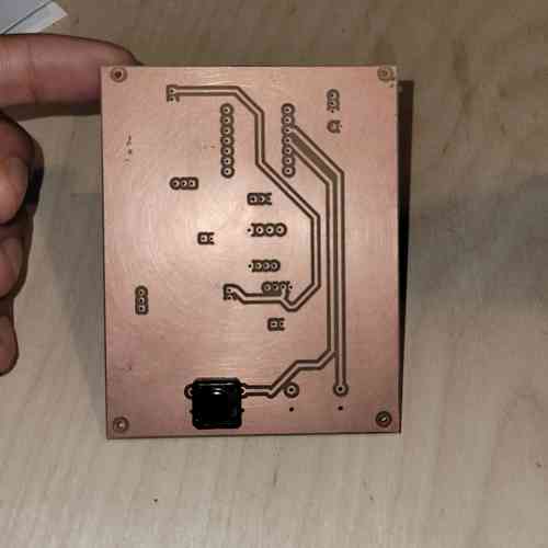
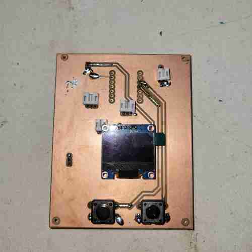
Annndd here's the back
Past Boards
Main Controller Board V1 -- NO LONGER USING THIS VERSION BUT KEEPING FOR DOCUMENTATION
Purpose: This board houses the XIAO ESP32-C3 microcontroller which will control the input/output functions of the device.
Notes:
- Since I will be supplying 5V power in via a battery, I use the VIN pin and MUST place a diode to ensure the flow of electricity stays in one direction. I used a Schottky SS34 Diode. See Seed studio's documentation here
Components for soldering:
- XIAO ESP32 C3 board
- Schottky SS34 Diode
- Resistor
- 4 socket JST connectors (1)
- 3 socket JST connectors (3)
- 2 socket JST connectors (2)
Here is the schematic for the main controller board in KiCad
Here is layout for the main controller board in KiCad
Here is the board after milling and stuffing with components! I used through holes for the JST connectors and soldered them on from underneath. I will mount the main controller board within the bottom base of the device to the left of the speaker and towards the top so that there is space for the wires to hook up from underneath.
Power Supply Management Board -- NO LONGER USING THIS VERSION BUT KEEPING FOR DOCUMENTATION
Purpose: This board will manage power from 12V battery supply. It houses two voltage regulators which provide a 5V power line and a 3.3V power line.
Notes:
-
To drop 12V down to 5V, I used the NCP1117 SOT-223 package
-
To drop 5V down to 3.3V, I used the AMS1117 SOT-223 package
-
The data sheets for both the above mentioned linear voltage regulators are very straightforward. I simply needed to add
-
After testing the board, I noticed the voltage regulators got hot. Will suggested making a ground plane or ground loop for the future. Also, I could make thicker traces and use more solder on them. I also realized there was a small tear in the trace from wear and tear. Once that was fixed it operated well with reliable voltages supplied.
Components for soldering:
- NCP1117 SOT-223 voltage regulator
- AMS1117 SOT-223 voltage regulator
- Polarized capacitors: 10uF, 10 uF, 10uF, 22uF
- 3 socket JST connectors (2)
- 2 socket JST connectors (3)
Schematic for my power supply management board
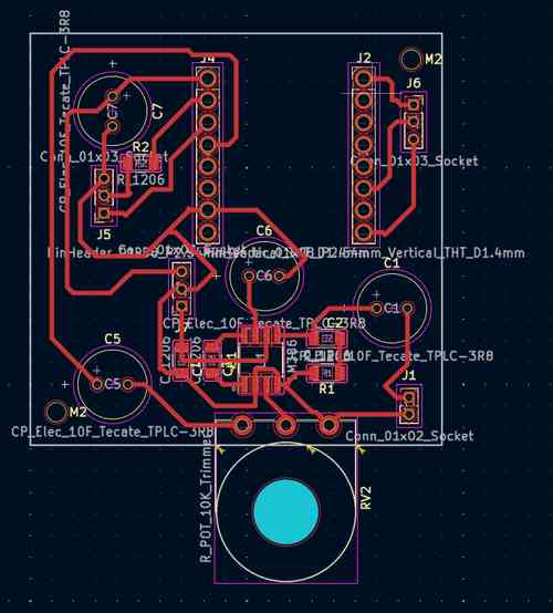
Layout for my power supply management board in Kicad
Here is the milled and stuffed power board. Extra solder has been added to thicken the GND trace for better operation.
Audio Board -- NO LONGER USING THIS VERSION BUT KEEPING FOR DOCUMENTATION
Purpose: This board will manage sound by having an audio amplification circuit and embed the DFPlayer Mini.
Notes:
-
The orientation of the DFPlayer Mini will be placed with the SD card facing the back of the device so there is easy access via a small slit
-
The orientation of the potentiometer in audio amplifier circuit will be to the front of the device so that the potentiometer knob can come through a front hole and be used for volume control. EDIT: I will actually just do a 3 pin header and solder wires to the potentiometer.
-
The length of the board should be close to the width of the base of the device. The width of the base of design as it is now is 2.25'' so I will make the board ~2.2'' in length. Scratch this: I will breakout the wires for the potentiometer for simplifying the assembly. I'll still need to make a slit in the back panel of the device for SD card access
-
After testing out speakers with various impedance and power, I found the best for this circuit with the LM386 audio amp was an 8 Ohm 1 Watt speaker. Using this at 12V actually worked fine with Gain set to 200 so I added in a capacitor at pins 1 and 8 o the LM386.
Components for soldering:
- DFPlayer Mini
- LM386
- Potentiometer
- Polarized Capacitor: 470 uF, 10uF, 10uF, 250uF
- 1206 SMD Capacitor: 0.1uF (=100 nanofarad), 10uF, 0.05uf (=50 nanofarad),
- 1206 SMD Resistor: 10 Ohm, 1KOhm
- 3 socket JST connectors (3)
- 2 socket JST connectors (1)
Schematic for my audio board
Layout for my audio board in Kicad
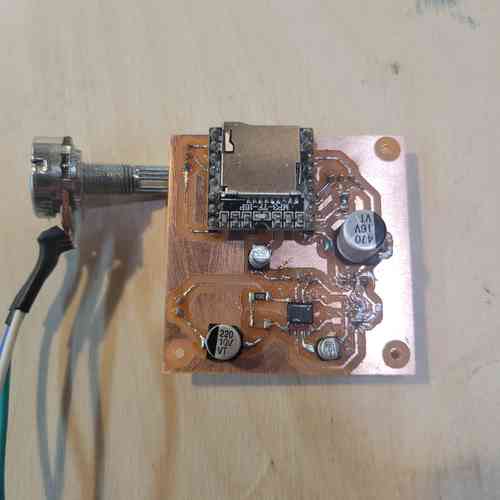
Here is the milled and stuffed audio board.
Compass Board -- NO LONGER USING THIS BOARD BUT KEEPING FOR DOCUMENTATION
Purpose: This board will house the magnetometer sensor a safe distance from other components that could affect its sensing of the magnetic field
Notes:
-
I am planning to use the GY-273 magnetometer module. This appears to house the HMC5883L but my specific module actually houses the VCM5883L sensor chip.
-
Finding code that worked with this was tricky. This DFRobot_QMC5883 page on GitHub provided code that worked for my board.
-
I will be placing this board the the very top of the device to keep it separate from other components, particularly the speaker (speakers have magnets in them to produce sound from electric current). During testing, 6 inches apart from the speaker worked for me
-
For clean wire management, I will wire the board to the interface board (which has the I2C bus anyways for other components)
Components for soldering:
- GY-273 Module
- 4 socket JST connectors (1)
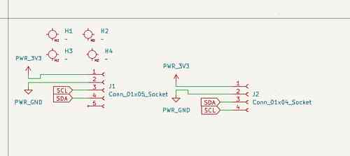
Schematic for my compass board
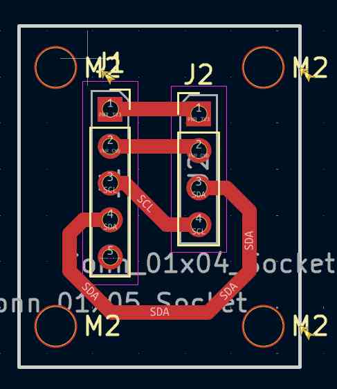
Layout for my compass board in Kicad
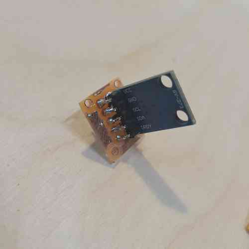
Here is the milled and stuffed compass board.
Interface Board V1 -- NO LONGER USING THIS VERSION BUT KEEPING FOR DOCUMENTATION
Purpose: This board will house the strip of buttons for interfacing with the audio player, the LEDs, the Grove-LCD, and the OLED screen. It will also provide wiring hookups for communicating with the compass board.
Notes:
- For the programming to run correctly, I will need a level shifter for the Neopixel because it "speaks" 5V but the XIAO runs at 3.3V logic levels. This post by Adafruit explains more. ACTUALLY, I found that the 3.3V works just fine for the Neopixel so I will just supply it with that unless I have issues.
Components for soldering:
- Buttons (3)
- 3 socket JST connectors (4)
- 4 socket JST connectors (4)
- 1206 SMD Resistor 220 Ohms
- polarized capacitor 100 uF
Schematic for my interface board
Layout for my interface board in Kicad. Note: mounting holes center placed 3.75mm x 3.75mm from corners
Here is the milled and stuffed interface board. JST connectors are through holes sticking out of the bottom side
Main Controller, Interface, Power Management Board V2 -- NO LONGER USING THIS VERSION BUT KEEPING FOR DOCUMENTATION
Purpose: This main board houses the XIAO ESP32-C3 microcontroller which will control the input/output functions of the device; it will consolidate the main board and interface into one by housing the components used for interfacing. This includes the buttons for interfacing with the audio player, the Neopixel strip, the Grove-LCD, the OLED screen (to be added in later spiral), and the accelerometer chip. This board also includes circuitry for power supply management using voltage regulators to convert 12V into 5V into 3.3V. In consolidating this, this makes for better systems integration in my electronics design, lessening the wiring and boards to be managed.
Notes:
-
Since I will be supplying 5V power in via a battery, I use the VIN pin and MUST place a diode to ensure the flow of electricity stays in one direction. I used a Schottky SS34 Diode. See Seed studio's documentation here
-
Since, I'm remaking the board, I will go ahead and add placements for pull-up resistors for I2C lines
-
I will now be using the ADXL343 Accelerometer chip for its motion detecting capabilities. I used the linked data sheet to figure out the circuitry. Some things I noted: tie CS pin high for I2C, tie ALT address low for I2C address at 0x53, must include external pull-up resistors on I2C lines (I did 4.7K Ohm), place decoupling capacitors close to VS/GND and VDDI/O+GND. I also wired INT1 and INT2 pins to use more of the chips capabilities.
-
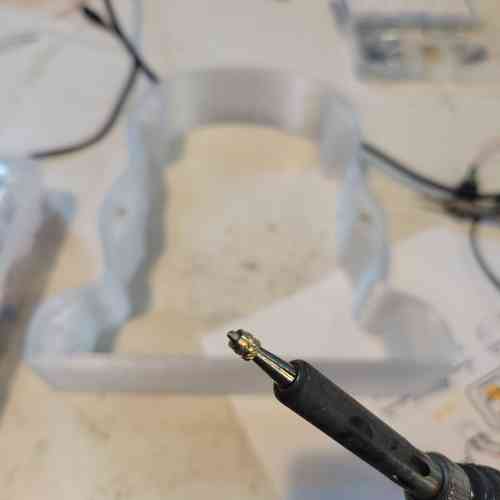
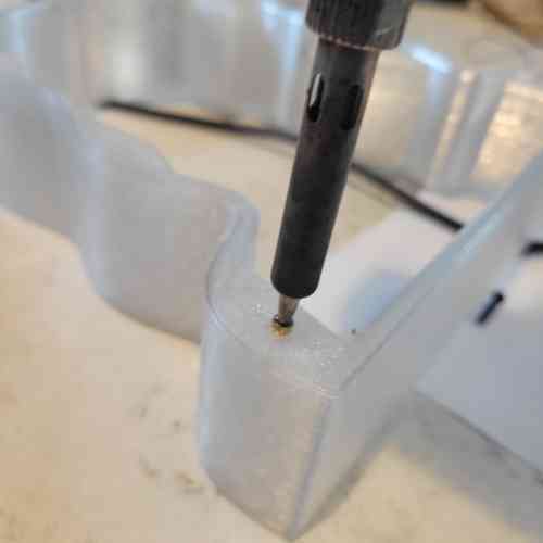
I also had to learn how to reflow and take extra care to solder the tiny little ADXL343 chip. I was scared but Will walked my through a practice lesson and with flux paste, a magnifying screen, good chip engineering, and steady breathing I got it on the board even with my shaky hands 🙏🏾
Set-up for soldering the tiny ADXL343 chip on circuit board. My workflow was: 1. Turn chip pins facing up and place on double sided tap 2. tin soldering iron with solder 3. add dab of flux paste to pins 4. apply solder in thin layer across pins allowing it to flow where it wants to flow and make sure there is no bridging 5. clean chip with alcohol and brush 6. add dab of flux paste to the circuit board where the chip will be placed 7. place chip on circuit board in correct orientation (the circle in upper left hand corner is near pin 1) 8. push down on chip slightly to get it in a good and aligned place. then remove your hand 8. apply hot air via heat gun near the chip and watch for it to set into place
-
I learned how to mill double sided boards! This Bantam Tutorial explains the process. I needed to make sure to toggle "top" or "bottom" for which side was milling and be sure to flip the board the correct way which Bantam makes easy to follow. Also, when milling the first layer, don't do the edge cut just yet.
-
Also, since the accelerometer chip is tiny, I had to use the 0.005'' Engraving Bit which needs special attunement with settings. Summary of settings changes:
Thickness: measure double sided copper plate with tape adhere and film remove. My plate measured at 1.80 mm thick

Trace Depth: Go to advanced settings and click customize trace depths. After some test runs with the engraving bit, I went with 0.07mm for the custom trace depth

Running the milling job with the engraving bit as if you're going to mill with a 1/64 in flat end and 1/32 inch flat end mill. Just cancel the job when you have completed the engraving bit portion. And reset normally settings (use default 0.20mm trace depth)
Components for soldering:
- XIAO ESP32 C3 board
- Schottky SS34 Diode
- ADXL343 Accelerometer
- NCP1117 SOT-223 voltage regulator
- AMS1117 SOT-223 voltage regulator
- 4 socket JST connectors (2)
- 3 socket JST connectors (4)
- 2 socket JST connectors (5)
- 1206 SMD Resistors: 0 ohms (8 for jumpers), 4.7Ohms (6 for I2C pullups), 330 Ohm (1 for Neopixel)
- 1206 SMD Capacitors: 1uF and 0.1uf (ADXL343 decoupling), 22uF (between 3V3 and GND)
- polarized capacitors: 10uF (3 for voltage regulators) 22uF (1 for voltage regulator), 100uF (1 for neopixel)
- Buttons (2)
- OLED screen
Schematic for my main board version 2
Layout for my main board v2 in Kicad. I designed for a two-sided PCB where one side is ground plane and a few traces.
Front side of the main board version 2
Back side of main board version 2
After a marathon 5+ hour late night session of soldering, I finally finished soldering this board!!
Other side of soldered board
Button Board -- NO LONGER USING THIS VERSION BUT KEEPING FOR DOCUMENTATION
Button Board
Purpose: This board will house a button for turning LEDs on.
Notes:
- This is broken out just due to the placement of the board in the bottom base of the device
- I'll need to keep this board small (under 1'' x 1'') so it will fit next to speaker and microcontroller board
Components for soldering:
- Button
- 2 socket JST connectors (1)
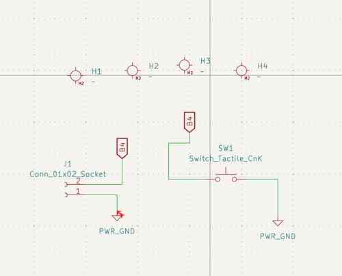
Schematic for my button board
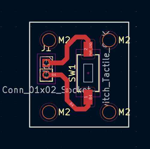
Layout for my button board in Kicad
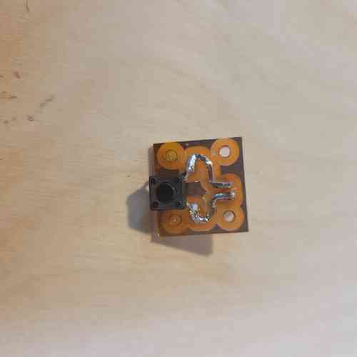
Here is the milled and stuffed button board.
Wiring and Assembly
In order to avoid having a mess of wires, I am using JST 2.00mm pitch connectors to group wires together. This has been integrated into my design on KiCad. I've also included M2 mounting holes so I can mount these boards in place within their enclosures or mounts. I will also add in threaded inserts for securing the panelling to the 3D printed inner wall, and (along with 3D prints) for securing several of the components in place such as the screens, speaker, batteries, and potentiometer.
Threaded Inserts
Placing threaded insert on soldering iron. Shiny lip faces up. I set the heat at around 200°C and eventually when I got to the acrylic/mirrored acrylic material of my laser cut panels, I set the heat around 285°C
Placing in the threaded insert carefully with consistent pressure making sure to go in as straight as possible so that it is flush with surface
Version #1
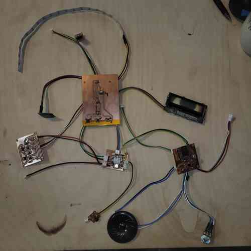
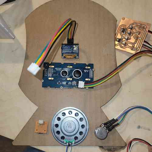
Here, I have all my boards printed and components wired up ready for testing
Here is an example of the connectors used for grouping wires. I soldered some of these on the bottom side of the board using the through-hole in the circuit board.

Here, I have laid out boards and components within the device to show assembly and fit.
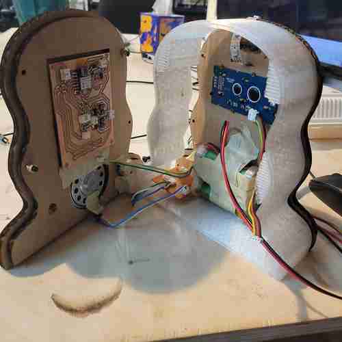
Here I'm laying down the components used for interfacing which will be mounted on the front panel. At this point, I've decided to change my design so that the front panel is CNC milled so that I can use 2.5D for fit. I will keep the back panel flat.
Version #2
I then made a major shift to consolidate boards to work on better systems integration.
Coming along with systems integration. I will still have wiring, but it will be much less to manage.
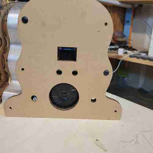
Front side of prototype 3. I have cutouts for the OLED screen, three buttons, a potentiometer, and speaker. I also have holes for M3 screws for added security
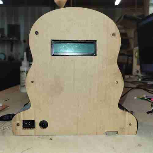
Back side of prototype 3. This includes holes for the on/off switch, recharging jack, SD card access, and LCD display. I also have hole for M3 screws for added security.
See final project page for final version with even better systems integration.
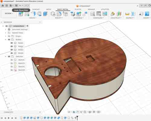
CAD for Systems Integration
I have now made a few prototypes for the overall enclosure of the device.
For my third round,
My CAD abilities are still beginner, but I sat down with Will to get tips on functions and techniques in Fusion 360 that would help me to make my final design. In summary:
-
For creating curves I can use the Create Fit Point Spline feature for the outline curve of my device. I can then extrude, mirror, and join the body. Doing it this way allows me to adjust the points on the sketch (after making it visible) within the regular design view to see in realtime how the overall shape would change by moving the points.
-
I can use offset and set that at a parameter value in useful ways. For example, I can extrude a cut-out for the circuit board within the inner front panel by creating a small (~0.005inch) offset from the rectangular sketch (which has circuit board's exact dimensions). Then I extrude that sketch and the tiny offset for a snug fit into the panel.
-
To place M3 screws for added security of the panelling and walls, I can take advantage of the additive manufacturing of the inner wall and just add small blips of extra material in a few places along the perimeter where I can place a hole for the screws.
Overall, I needed to rework the overall shape and size it down, add interface features (button holes, speaker, screen display holes, SD card access, on/off switch and recharge jack), create a mount for batteries (Will shared with me an example design for encasing batteries and its 18650 Battery Protection Module which I will use for my project), and to add mounts for ensuring a secure device where everything stays in its place.
Below are some screenshots from the CAD design on Fusion:
Front view of paneling and inner wall. You can see the cut outs for the various components and circuit boards. Also, I have designed an enclosure mount that will fixture the batteries in place as well as an imprint along the back panel for that to rest in. I have also dimensioned cutouts for the audio amplifier circuit board that allows for secure placement and SD card access. I still need to make a 3D print for holding the speaker securely in place.
Back view
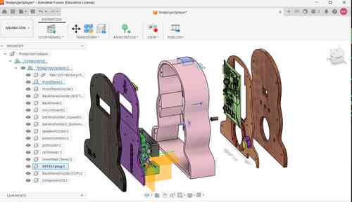
Updated CAD design. Figured how to import a 3D rendering of circuit board designed in Kicad! This was helpful in later weeks for easily measuring mounting holes, button holes, and screen placement.
Bill of Materials
Here is the updated draft Bill of Materials for electronics. Much of this we already had around the lab. For final official bill of materials I will add in materials for encasing (3D printing filament used etc.)
| Component | Info | Quantity | Price | Total |
|---|---|---|---|---|
| Neopixel Strip | 2541 | 20 (LEDS) | $0.47 | $9.34 ➡ (I used part of a strip) |
| Speaker | AS02808MR-R | 1 | $4.53 | $4.53 |
| JST Connector and Wire | YO-2503-2.0-Kit-HY | 10 | ~$0.37 | $3.70 |
| Accelerometor | ADXL343BCCZ | 1 | $3.69 | $3.69 |
| Linear Voltage Regulator 3.3V | AMS1117-3.3 SOT | 1 | $0.10 | $0.10 |
| Linear Voltage Regulator 5V | NCV1117ST50T3G | 1 | $0.59 | $0.59 |
| Audio Amplifier | LM386M-1 | 1 | $1.33 | $1.33 |
| Potentiometer | TEKFA4076 | 1 | $1.99 | $1.99 |
| M2 Screws and Socket | 0P7L4P97S1Z95 | 20 | ~$0.09 | $1.80 |
| XIAO ESP32-C3 | 113991054 | 1 | $4.99 | $4.99 |
| 12V Rechargeable Battery | L111A26-3-2-2W | 1 | $27.64 | $27.64 |
| Battery Protection Module | 18650 | 1 | $3.90 | $3.90 |
| DFPlayer Mini | DFR0299 | 1 | $6.88 | $6.88 |
| 8G SD Card | U1 5Units | 1 | $8.38 | $8.38 |
| Button | FSM2JSMA | 4 | $0.28 | $1.12 |
| Rocker Switch | GRB112D802BB | 1 | $4.54 | $4.54 |
| Resistors 0603 | PHH5-KIT | 4 | ~$0.01 | $0.04 ➡ Breakdown of resistors used: 10Ω (3), 470Ω (1) |
| Capacitor 1206 | 618202981142 | 12 | ~$0.01 | $0.12 ➡ Breakdown of capacitors used: 220nf (1),100nf (4), 10uF (1), 0.05uF (1), 10uF polarized(3), 250uF polarized (1), 1000uF polarized (1) |
| Current Total | $133.87 |
Systems Integration Design
See below for my original documentation for this week. Keeping this here for my own notes and reference. I'll work on consolidating.
Preliminary Research and Considerations
In preparation for this week, I decided to finish a book I borrowed from FAB NODA's library The Design of Everyday Things by Don Norman. The main message I got was that if there's an issue with using a device or tech then it's not you, it's bad design 😅. The emphasis on human-centered design interested me and helped me to think more deeply about the experience of using the music player for my final project. Some new considerations include:
Music Player Device Considerations
- How will the compass feature work? > I think it would make sense to have the device held horizontal to the earth with some visual indicators (like a red arrow) integrated into the design that make it more intuitive for how to use it. I also think adding a feature on the screen that displays a simple "N" "SW" "E" etc. in addition to the moving compass would be helpful. I will need to be careful about how the magnetometer component is placed (i.e. where are the X and Y axes). Something that could help this would be adding handles on the side that you can use to hold it flat
- Buttons, buttons, buttons rather than have a confusing mess of buttons, I want to make sure to design buttons that are widely familiar (so, play/pause symbol, next track and previous track buttons), and for the fun LED light button I will include a label or a symbol of light turning on. I'd also love a traditional on off switch in the back that directly turns power on or off. Also, maybe move the audio potentiometer down closer to the speaker since it'll probably be more intuitive that it corresponds to audio if it's right next to the speaker
- Think about how the design can embed the neopixel LED strip within the encasing.
- OLED screens This might be ridiculous but I'm thinking to have two OLED screens, one dedicated to the compass/temperature feature and another dedicated to displaying the audio track title. I also am thinking to include some engravings above the screen to indicate what data is being displayed: a red(painted?) engraved arrow by the output that shows direction, an engraving of a compass over where the arrow will be changing directions, a sound wave symbol over track titles are displayed, and a temperature symbol where the temperature will be displayed.
- IMPORTANT REALIZATION: while looking through speaker options I was reminded that they are magnetic and thus it will impact the magnetometer's sensor readings. I did some initial testing to get a sense of what range and orientation of objects impact the readings. It looks like if I keep these components as far apart as possible. 6 inches apart with the components both oriented face up is around the threshold, so for the design I will plan to place those components 9 inches apart to stay safe.
The magnetic field of the speaker impacts the magnetometer sensor when placed nearby
Charging Device Considerations
- Adding in LEDS that indicate when the batteries are fully charge will make this more useable
- Rather than laying the music player flat, it's more space efficient to stand it up-right. For secure-ness of the device, it would be ideal to have a snug or click-in-place type of fit for this
- How will the batteries hook up into the sockets for charging?
Power Supply Management
Music Player Device
| Component | Operating Voltage | Notes |
|---|---|---|
| DFPlayer Mini | 3.2V - 5.0 V | I will need to connect to power on XIAO board |
| NeoPixel RGB LED strip | 5V (lower could mean dimmer/wrong color lights) | I am going to test how 3.3V. I will add a capacitor as an added power reservoir. Always connect ground before anything!!! Add 300-500 Ohmn resistor |
| OLED | 3.3V - 5V | Will work fine with XIAO board power |
| MLX90393 | 2.2V - 3.6V at 100µA | Will work fine with XIAO board |
| LM386 Audio Amplifier | 4-12 V (or 5-18V) | I will power this using separate battery supply (ex. 7.4V)load impedance for speaker 4 - 32 Ohm |
| Speaker | voltage corresponds to sound.. | still need to figure out what speaker i will use |
| XIAO ESP32-C3 | 3.7 (battery) (5V for VIN) | rather than a USB cable, I will figure out how to connect batteries as shown on board diagram |
Charging Device
| Component | Operating Voltage | Notes |
|---|---|---|
| ATTiny85 | 1.8V - 5.0 V | I will need to connect to power |
| LED* | forward voltage of 1.8 V - 3.3V depending on color | |
| insert remaining components* |
Comparing Batteries
Found this beginner's guide online on rechargeable battery options. Took notes on a few below (I didn't see there was already a comparison table til on the website til I got to the end 😅)
| Component | Voltage | Capacity | Notes |
|---|---|---|---|
| Lithium-ion 18650 | 3.7V per cell | 2000-3500mAh | high energy density, fast charging; I could use 1 cell for XIAO board and 2 additional cells (7.4V) for audio amplifier circuit |
| LiFe P04 (Lithium Iron phosphate)* | 3.2 V | 500 - 3000mAh | best for solar; known for long cycle life and safety and less likely to overheat; lower voltage could complicate things -- is 3.2V enough to power XIAO and all the components? if not, would need to think through voltage regulation here. |
| Rechargeable Li-Po (Lithium polymer) packs | 3.7V per cell | 500-5000+mAh | high current output makes for high power performance projects BUT can be dangerous if overcharged |
Design Plan for Power
At this point, I have decided to have a 12V rechargeable battery source and use a 5V and 3.3V low dropout voltage regulator for converting the voltage. So in all I will have a 12V line for the speaker and its related components, a 5V line for the Grove-LCD screen and for the Neopixel LEDs, and 3.3V for the XIAO microcontroller and the remaining components. We have
NOTE: for the LSM303AH component (magnometer I plan to use) I need to be mindful of current. The datasheet says to keep currents within a few millimeters of the sensor IC UNDER 10mA near the device under 10mA. I will plan to place the circuit board for this at the top of the device and concentrate the other circuit boards and batteries near the bottom of the device.
Circuit Board Management
I am planning to have six boards:
1) The main microcontroller board will have an embedded XIAO ESP32-C3 board and have pin header connectors for the pins, 3.3V, and GND as well as wiring to the 3.3 power supply line. NOTE: I will actually be supplying the Xiao power by using the 5V power pin as a voltage input. To do this I must have a diode placed between external power source and the pin. (see Seed studio's documentation here
2) The voltage regulator board will convert down the 12V power supply from the battery pack into two power lines: 5V and 3.3V
IC Reg Linear 5V https://www.digikey.com/en/products/detail/onsemi/NCV1117ST50T3G/1792666 --> should be able to use this for both 5V and 3.3V power lines!
TL431 voltage regulator
AMS1117 3.3 Volt SOT - 223** (plan for this if using 3.3v) (more current than IC Reg Linear 3.3V 100mA SOT23-3; bigger footprint too) --> this is in the 0805 SMD resistor book the lab has
3) The audio and audio amplifier board will amplify audio to the speaker and embed the DFPlayer Mini. On one side, there will be a hook up to a potentiometer that extrudes out a smlal hole in the front panel. On the other side, the DFPlayer mini will be placed with the SD card insert side facing the back panel which will have a slit for easier access (slit should be ~0.2'' and 0.5'' above base of the circuit board). The length of the boards should be close to the width of the base of the device. As an alternative, I could make this into two boards
4) The compass board will house a working sensor to give out readings for the compass display. For accurate readings, this board should be kept as far away from the speaker as possible (at least 6 inches) AND should avoid high currents within a few millimeters of the IC sensor. I will also need to place this vertically so that the XY axis aligns with the front plane of the device. The footprint for the LSM303AH is LSM303C in Kicad.
UPDATE: I found out from the datasheet, that supply voltage on any pin should never exceed 2.2V! I will need a way to 1) Convert power down to its working range (1.71 - 1.98V) and 2) a way to translate the converted voltage logic so that the ESP32 and the LSM303AH can communicate. I will start by learning how to do a voltage divider circuit which uses two high value resisters in series and taps an output voltage in between. The chip we had available in the lab for translation is the TXB0104Dr.
I used this voltage divider calculator online. 4mA is max driving capability
Voltage divider that adds up to about 3.3K
Math: 3.3V divided by 0.001 (1 milliamp) which will be needed for driving I/0 pins and the sensor. (Max is 4 milliamps!) -- with I2C we need to tune amount of currents available when we're flippng those bits around. Using the calculator, I found that I could set R1 at 1.5KΩ and R2 at 1.8KΩ.
ACTUALLY the translation chip doesn't work with I2C --> instead going to order TXS0104E
5) Button board #1 will be a strip of buttons for interfacing with the audio player and be placed along the front panel
6) Button board #2 will be just one button and will turn the LEDs on
Note on remaining components: The Grove LCD, OLED, and speaker will be mounted using M2 screws. I will use pre-crimped cables for secure wire management of everything. For the LEDs, I will need to create a small hole in the 3D printed encasings as an outlet for the LEDs
!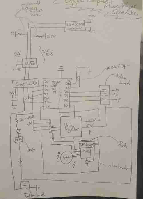
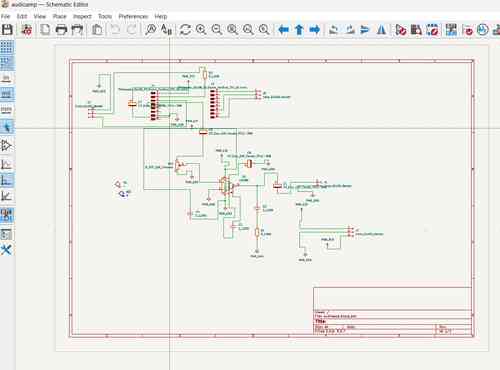
Updated schematic for my final project incorporating systems integration planning
Prototyping
Electronic Breadboard Circuit
Challenge #1: Connecting two screens to I2C line on XIAO board with separate displays
I spent many hours testing out screens and ultimately landed on using the SSD1306 0.96 inch display for the compass reading and then the Grove-LCD RGB Backlight for listing out the track titles and temperature.
I kept running into an old problem: the backlight colors would display on the Grove LCD but no text. LOTS of troubleshooting later and come to find out it just needed 5V of power rather than 3.3V to achieve full functionality.
As a part of my testing, I tried using another OLED screen but couldn't get the screens to have different displays -- there was a lot of confusion with them sharing the same libraries. For this reason, I like using the Grove-LCD because it refers to a different library.
However, I will need to have a 5V power line available for it to work. Probably not a bad idea anyways because my LED lights will likely function better at 5V anyways. The XIAO board only provides 5V when plugged in via USB but since I will be using batteries I cannot plan to use that line. Therefore, I will need to convert power for the speaker into 5V because I also can't go over the amount of power because that could damage the screen.
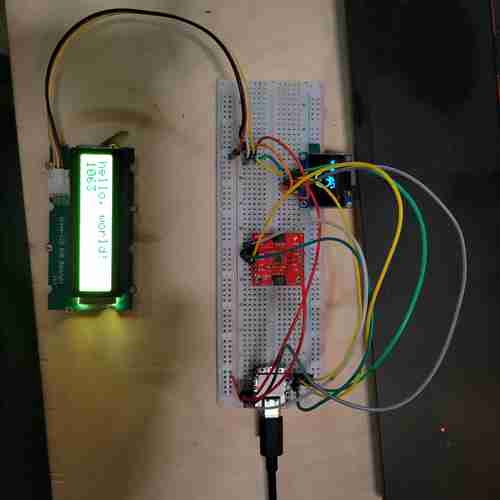
Here, two screens hooked up to the same I2C line are working and displaying separate things. The OLED displays the compass while the Grove-LCD displays hello, world!
Challenge #2: Add in an LED + button
Now that the screens and compass are working, I want to try adding in the LED strip with button.
Referred to this guide for wiring and test code for the Neopixel light. I used an external power source into breadboard, I added a 330 Ohm resistor and a 100 microfarad polarized capacitor (although it would turn out the neopixel strips I was using alread had capacitors built in so this might be redundant).
For the longest, I couldn't figure out why the LED wouldn't turn on. After swapping out LED strips and finally getting that to work, I realized my wiring was messed up! Turns out, I was using the data output line rather than data input side of the LED strip. Once I corrected for this, they worked
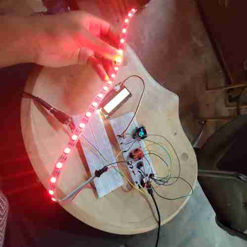
Here, two screens still work with the LED strip and button added
Something I will need to troubleshoot: timing and delays in the code particularly when buttons are pressed.
Something to note: if I power at 5V, it is highly reccomended I use a level shifter with the NeoPixel since it "speaks" 5V but the XIAO runs at 3.3V logic levels. This post by Adafruit explains more. For now, I will plan to power the Neopixel at 3.3V to start.
During later testing, I found this Arduino forum post with code from user Grumpy_Mike that worked for me to use a push button to toggle the light strip on and off.
--
As a last step, I need to connect all the audio-playing related components. I will work on this in the following weeks.
Audio
Got the DFPlayer Mini up and running. The code provided on this website worked for me but I had issues with code in other sources I've found. I added a 100 microfarad capacitor across power and ground near the DFPlayer device. Note: file naming conventions key -- see datasheet. ex. name files "001.mp3" to correlate to code line "player.play(1)" or "004.mp3" to correlate to code line "player.play(4)." Reproducing code below for easy access:
// Code from esp32cube tutorial https://www.esp32cube.com/post/esp32-mp3-tf-16p-dfplayer-mini-guide

#include <Arduino.h>
#include <HardwareSerial.h>
#include <DFRobotDFPlayerMini.h>

static const int MP3_TX = 21;   // ESP32 TX -> module RX
static const int MP3_RX = 20;   // ESP32 RX <- module TX
static const int MP3_BUSY = 10; // LOW when playing

HardwareSerial mp3Serial(1);
DFRobotDFPlayerMini player;

void setup() {
Serial.begin(115200);
pinMode(MP3_BUSY, INPUT);

mp3Serial.begin(9600, SERIAL_8N1, MP3_RX, MP3_TX);
delay(500);

if (!player.begin(mp3Serial)) {
    Serial.println("DFPlayer init failed");
    return;
}

player.volume(25); // range: 0..30
player.play(4);    // play 0001.mp3
Serial.println("DFPlayer ready");
}

void loop() {
const bool isPlaying = (digitalRead(MP3_BUSY) == LOW);
Serial.println(isPlaying ? "Playing" : "Idle");
delay(1000);
}
And here are some common playback APIs mentioned on the website:
player.play(1);         // play track index 1
player.pause();         // pause
player.start();         // resume
player.stop();          // stop
player.next();          // next track
player.previous();      // previous track
player.volume(25);      // set volume 0..30
player.randomAll();     // random playback (library version dependent)
player.loop(1);         // loop a track index
Testing it with my old LM386 audio amplifier board: It works but there is a lot of extra noise. I made the following modifications on the audio amplifier circuit:
- Routed pin 7 of the LM386 to GND and added in a 10uF capacitor
- Plan to use an 8 ohm speaker rather than a 4 ohm speaker. This blog helped explain that the LM386 was designed back in the days for 8 ohm speakers but doesn't perform well with 4ohm speakers. I
-
Set the gain down to 20 by removing the capacitor between pins 1 and 8 of the LM386 (see video for audio difference in testing) >> I will keep it on the schematic/board so if I need to add this back in
-
I did not account for the need for 3.3V to power the DFPlayer. I will need to either change my voltage regulator board(probably easiest option) or add another 3.3V/GND pinheader on the main microcontroler board. I'll plan for voltage regulator board: I can take away the 12V/GND pin header that is going to the audio amp board and add in one towards the bottom righthand corner that is a header with 3.3V > GND > 12V in that order for ease of routing.
Here is the noise level with the Gain = 200. You can here radio frequency signal and other static noise. I am testing at 5V.
Here is the noise level with the Gain = 20 (after removing the capacitor on board between pins 1 and 8 of LM386). I am testing at 5V
Here i am testing at 12V with Gain = 20. I made sure to share ground between XIAO and LM386. The noise is much better
Compass Testing Now, I need to test and calibrate my GY-511 module.
I found this code on Github to use for testing. Although it is
For the life of me, I could not get a GY-511 module to work reliably
Next using GY-273. Found this code on Github
Prototype Design
Took a break from electronics to develop a draft design in Fusions and incorporating the considerations I have come to so far. At this point, I have updated my final project concept to have the primary function of operating as a digital compass so I wanted to the design to have those references.
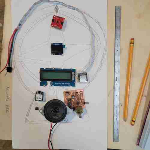
Updated sketch of my final project design with some of the components placed
In Fusion 360, I simply created a sketch outline based on my sketch, extruded it, and shelled it to have three bodies: two outer panels for laser cutting and an inner wall for 3D printing.
Initial design on Fusion 360. This week I focused on the outer panels for laser cutting and taking note of design considerations needed
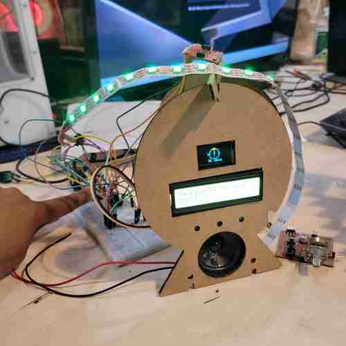
Here is the basic prototype! So far, the screens, LED strip, magnometer, and button for the LED are working
Quick design notes...At this point, I would like the final design to have:
- the inner wall to include star-shaped cut-outs that will have a press-fit 3D printed counterparts
- the inner wall to include rungs (or a sleeve of some sort) along the inside of the print where the neopixel light can slide in
- the front panel to have a compass engraving design
- the back panel to have a hot air balloon engraving design and maybe a quote
--