Week 11: Networking and Communications
Our assignment:
Group Assignment: send a message between two projects
Individual Assignment: design, build, and connect wired or wireless node(s) with network or bus addresses and local input &/or output device(s)
Individual Assignment
For this week's assignment, I decided to learn how to use the ESP-NOW wireless communication protocol to communicate between some boards I have already designed. I used XIAO-ESP32 microcontrollers and referred to this page on Arduino's documentation website and this page on Random Nerd Tutorials' website to get started.
The ESP-NOW protocol is a peer-to-peer (P2P) protocol where each ESP device is identified by its unique MAC ("medium access control") address. ESP-NOW can do one-way communication and two-way communication. Some quick notes from Random Nerd's site on flow of the code for P2P communication:
One-Way Communication
Send Data to another board (main board):
- Initialize ESP-NOW
- Register callback function after sending data - OnDataSent function is executed when message sent
- Add receiver device with its MAC address
- Send message to receiver device
Receive Data from board (secondary board):
- Initialize ESP-NOW
- Register for receive callback function - OnDataRecv function is executed with message received
- Save message into a variable to execute any task
To get the MAC address of the receiving board, I uploaded the provided code on the website reproduced below:
// Complete Instructions to Get and Change ESP MAC Address: https://RandomNerdTutorials.com/get-change-esp32-esp8266-mac-address-arduino/

#include "WiFi.h"

void setup(){
Serial.begin(115200);
WiFi.mode(WIFI_MODE_STA);
Serial.println(WiFi.macAddress());
}

void loop(){

}
Looking at the Serial Monitor screen, I see that the MAC address for my receiving device is: 58:8C:81:AE:41:6C
Doing the same for the sending board, I see the MAC address for my sending device is: B0:A6:04:06:3A:5C
Next, I used the provided code (see design files below) and inserted the MAC address where indicated to upload to my sender board and the provided code to upload to my receiver board. Checking the serial monitor shows that the data was sent and received with success!
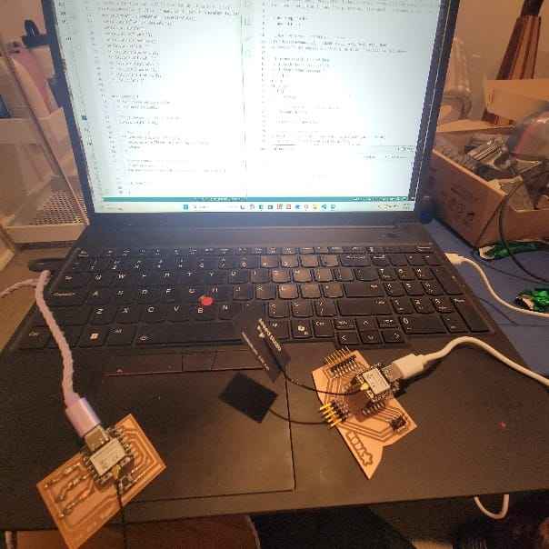
Setting up boards for wireless communication
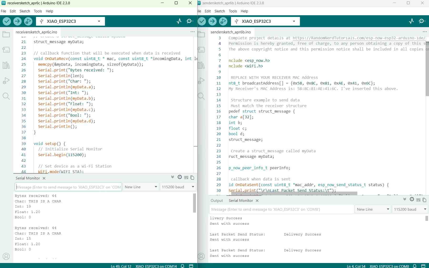
Serial monitor shows delivery success
That was simple enough. Now I want to challenge myself. I have my "You are light" microcontroller board from Week 8 which has three LEDs on it (Green - Yellow - Red). I have my general use microcontroller board that gives me a lot of options to play around with. And I have a 128 x 32 OLED screen display and a temperature sensor that I've been wanting to put to use. So my challenge to myself is to get the screen to display a read-out of the temperature and to have the temperature affect my other microcontroller so that it will light up an LED to indicate relative temperature (so red for when its really hot, yellow when is less hot, and green when its cooler...I'll just make this up).
Many hours of referring to reference code, integrating different pieces, trial and error, and consultations with Deepseek I got to a good place. (See design files for code + Deepseek prompt). The main issues I struggled with was getting the temperature sensor to work and the OLED screen to work. At first, the temperature sensor was only giving back "nan" results in the serial monitor. I found that the code I was using was for 10-bit ADC Arduino boards whereas the XIAO ESP32-C3 board I was using has a 12-bit ADC so the resistance calculation in the code doesn't work. Another issue I ran into with the code was with the libraries referenced. For example, I received "Adafruit_SSD1306.h:no such file or directory"error code even though the library was installed and worked in the past. For future reference, I will take care to use #include statements in the right order because some libraries need others to be loaded up first. Another error flagged by Deepseek was that the version of my XIAO board used a different callback function signature than its earlier version. This is updated and noted in the code (design file). Last small thing I kept getting wrong: the OLED display I had uses 0x3C NOT 0x3D. Make sure this I2C address is correct when initializing.
Eventually, I successfully connected the temperature sensor and OLED to my main board, displayed the temperature on the OLED screen, and communicated the data to the receiver board which I verified through serial monitor.
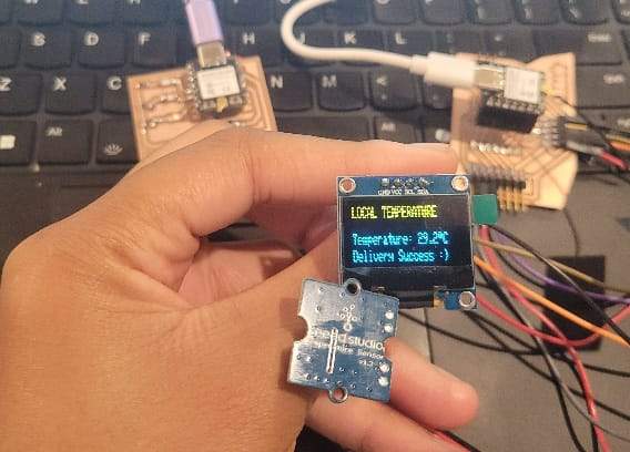
Working temperature sensor + display
Next, I wanted to figure out the code for the receiver board. I made sure to match the sender structure message and adapted it to reflect the temperature readings. I got a few error messages along the way but referred to Sender board code with some educated guesses. Eventually I figured it out!
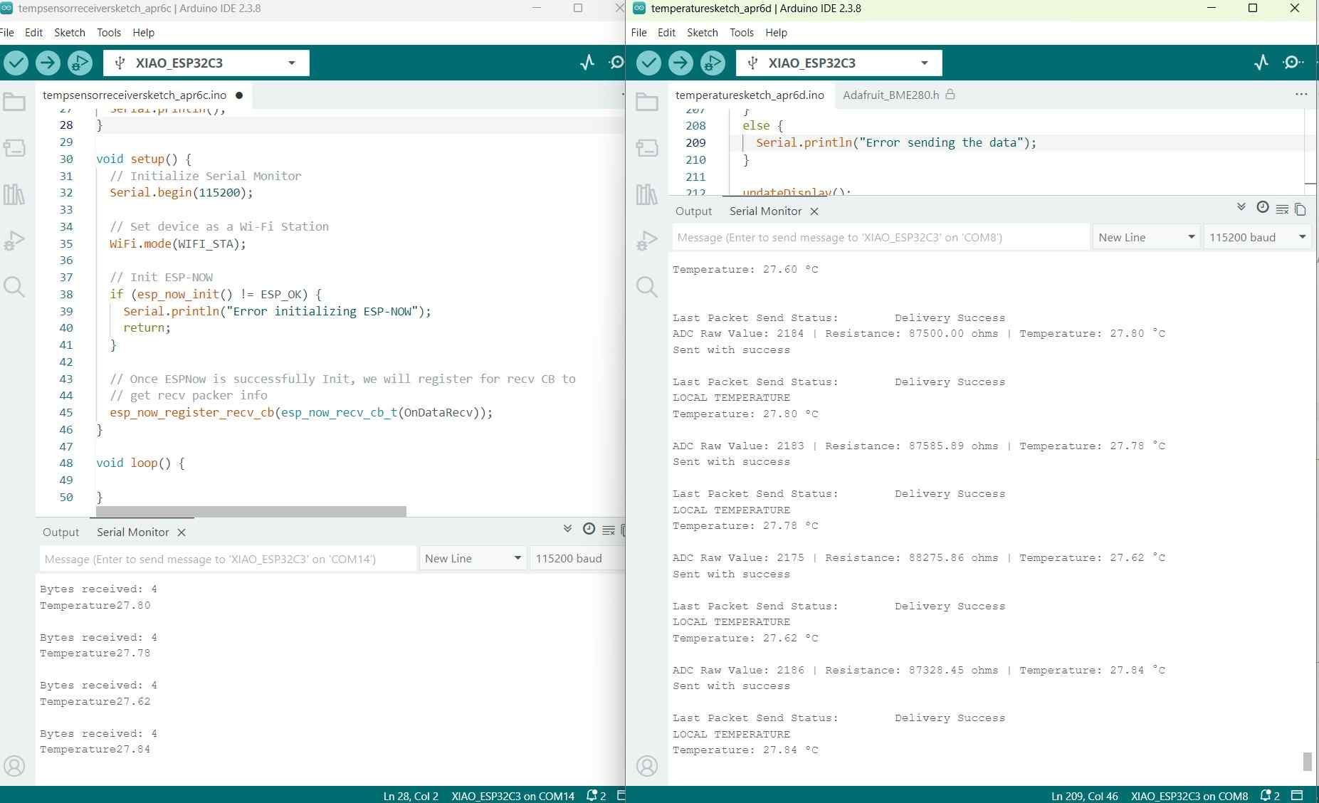
Looking at the serial monitor for each microcontroller, you can see how the receiver (on the right) receives a periodic read of the temperature. The monitor on the right provides a read of temperature and reports delivery success to the secondary board.
Now, I just need to figure out how to get the LED's to turn on. I referred to my code from Week 8. In my first attempt, I got the LED to light up green when the temperature went above 30 degrees C! And once it cooled back down it went off again. Once I confirmed that would work it was easy to write the rest of the code -- I wanted to make it so that above a certain temperature the light would turn red, between certain temperatures it would be yellow, and below a certain temperature it would be green.
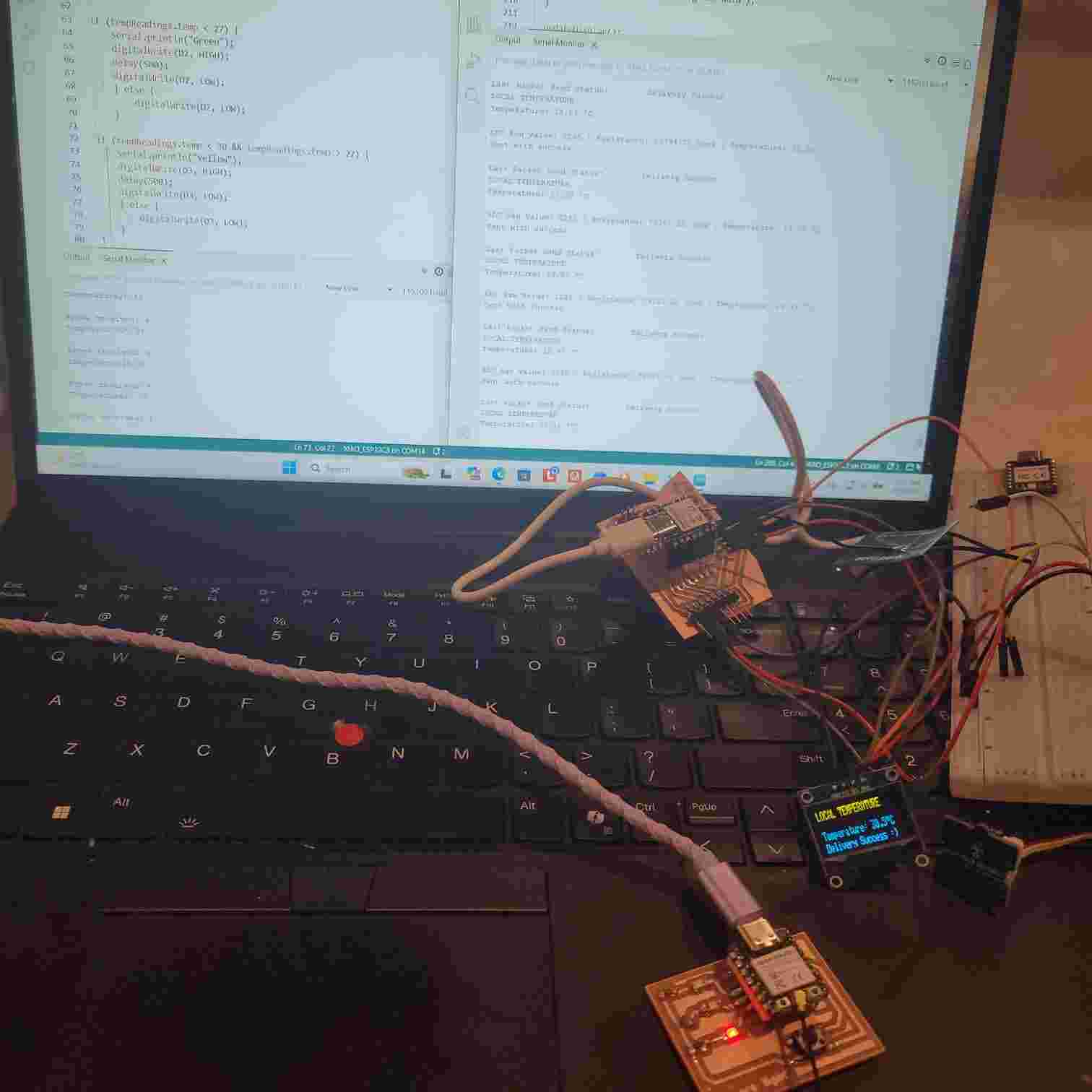
At a higher temperature, the LED board lights up red
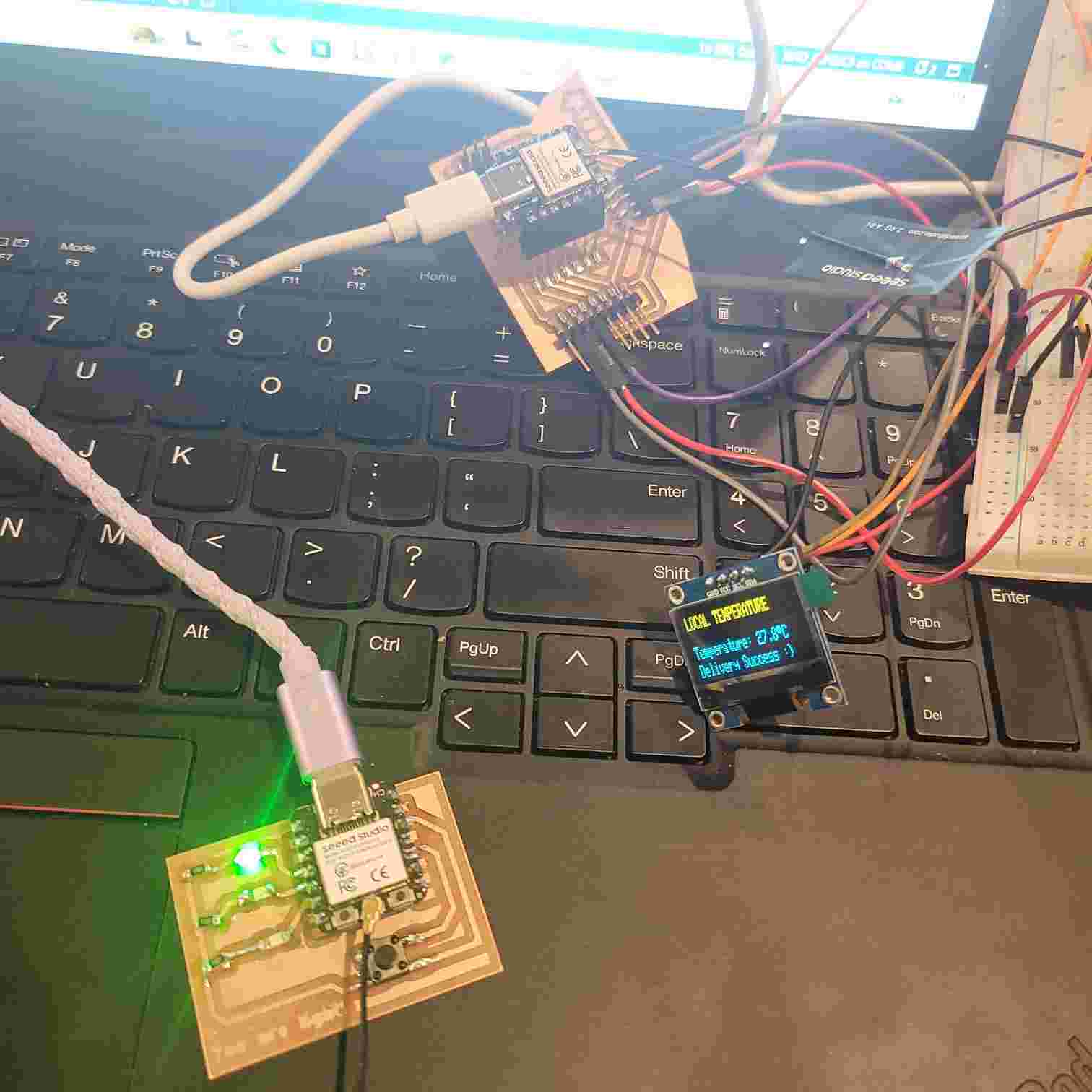
At a lower temperature, the LED board lights up green
When I turn on the heater, the temperature sensor senses increasingly higher temperatures. As the temperature increases, the LED board receives the readings and goes from green to yellow to red as it gets hotter. The serial monitors of each also display readouts of temperature and other data.
To improve this, I could calibrate the temperature of the sensor since the readings are a bit higher than the actual room temperature.
Group Assignment
Find our group assignment documented here with more pictures and design files and my documented learnings below.
For the group assignment, we decided to extend the project I created for my assignment this week to communicate using ESP NOW with another board which Will created which can connect to bluetooth and was programmed to put out audio.
To complete this, we would need to update the sender code for the main board so that it will detect Will's receiver board. Also, we would need to create receiver code so that the board will receive and use that data. For this assignment, we wanted to have the board output audio tones (via bluetooth speaker) that change frequency based on the temperature readings.
To do this, we ran the simple code for printing the MAC address in the Serial monitor display. The MAC address for for Will's board is: 80: F1: B2: 61: A7: 94.
Now, I could update the code with this and a few other sets of updates to account for there being two receiver boards now.
Next, we had to create the receiver board code. This would need to integrate the template receiver board code (used for angela's LED board) with matching structures for receiving data and the code Will used for audio output which used Mozzi, a sound synthesis library for Arduino.
Communicating temperature sensor data to two receiver boards. As hot air is blown around sensor, the frequency tone emitted by the output audio device gets higher in pitch. When the sensor is placed on the freeze pop, the sensor gets colder and reads a lower temperature, causing the audio output frequency to lower.
Other Learnings
Though for my individual assignment, I practiced using wireless communication, I did dabble in wired Inter-Integrated Circuit aka "I2C."
Found this read A Basic Guide to I2C by Texas Instruments helpful. And also the I2C bus manual linked on FAB Academy's site. Basically, its a bus line connection that connects devices (main and/or secondary/target devices) for communication across a short-distance using 2 lines: Serial Data (SDA) which transfers data and Serial Clock (SCL) which transfers clock signal.
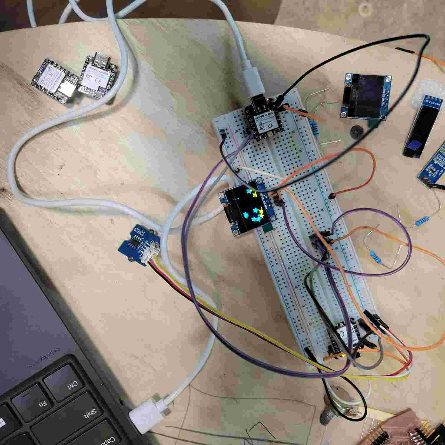
A simple breadboard wiring set up between two XIAO-RA4M1 boards. I used Seeed Studios' Getting Started page for this board to install the new board and read up on its documentation. I learned to share ground between microcontrollers but DON'T share power. I also learned to create a "bus" between the microcontrollers using the SDA + SCL pins. This was also wired to an OLED screen display.
Also, I began looking into resources for LoRa radio. Taking note of resources for future reference below:
- Meshtastic's website and Miriam's smart bike tracker project
- Heltec Wireless Tracker V2 board and solar kit
- Sparkfun's guide on sending sensor data over LoRa
Didn't have much time to go deeper this week, but will keep at it for final project development.
Design Files
Here is a link to my design files for my individual assignment from this week.