Week 11: NETWORKING AND COMMUNICATIONS
group assignment: • send a message between two projects
For the group assignment, we decided to extend the project angela created for the individual assignment this week to communicate using ESP NOW with another board which Will created which can connect to bluetooth and was programmed to put out audio.
Here is the board Will created that outputs audio via bluetooth
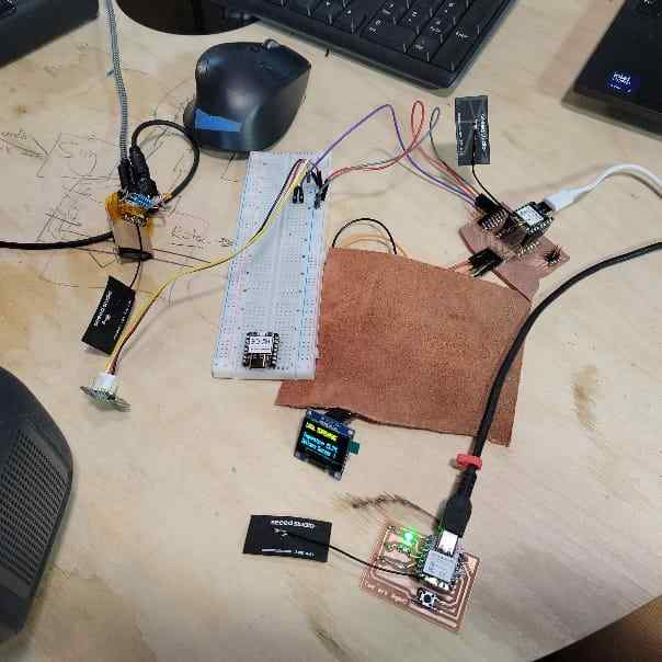
Here is our set up for the group assignment networking
To complete this, we would need to update the sender code for the main board so that it will detect Will’s receiver board. Also, we would need to create receiver code so that the board will receive and use that data. For this assignment, we wanted to have the board output audio tones (via bluetooth spekaer) that change frequency based on the temperature readings.
To do this, we ran the simple code for printing the MAC address in the Serial monitor display. The MAC address for for Will’s board is: 80: F1: B2: 61: A7: 94.
Now, we could update the code with this and a few other sets of updates to account for there being two receiver boards now.
Next, we had to create the receiver board code. This would need to integrate the template receiver board code (used for angela’s LED board) with matching structures for receiving data and the code Will used for audio output which used Mozzi, a sound synthesis library for Arduino.
Communicating temperature sensor data to two receiver boards. As hot air is blown around sensor, the frequency tone emitted by the output audio device gets higher in pitch. When the sensor is placed on the freeze pop, the sensor gets colder and reads a lower temperature, causing the audio output frequency to lower.
Design Files
Find a link to our design files here.
Using an accelerometer to turn on an LED.
How I did it
My goal this week was to create wireless communication between 2 ESP32C3. To do this, I used a guide from RandomNerdTutorials
I need the ESP on my Armband board to communicate with the ESP on my Bloomboard. When the ADXL343 detects movement, I want it to turn on a LED.
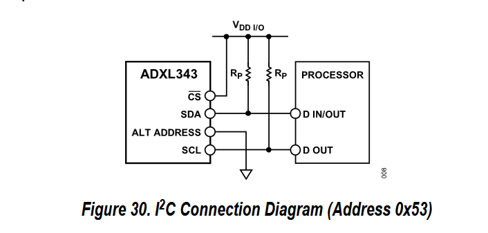
Wiring
I used this beautiful datasheet for the ADXL343. It had all the information I needed to know, however I ran into many problems because I had to learn where the information I needed was.
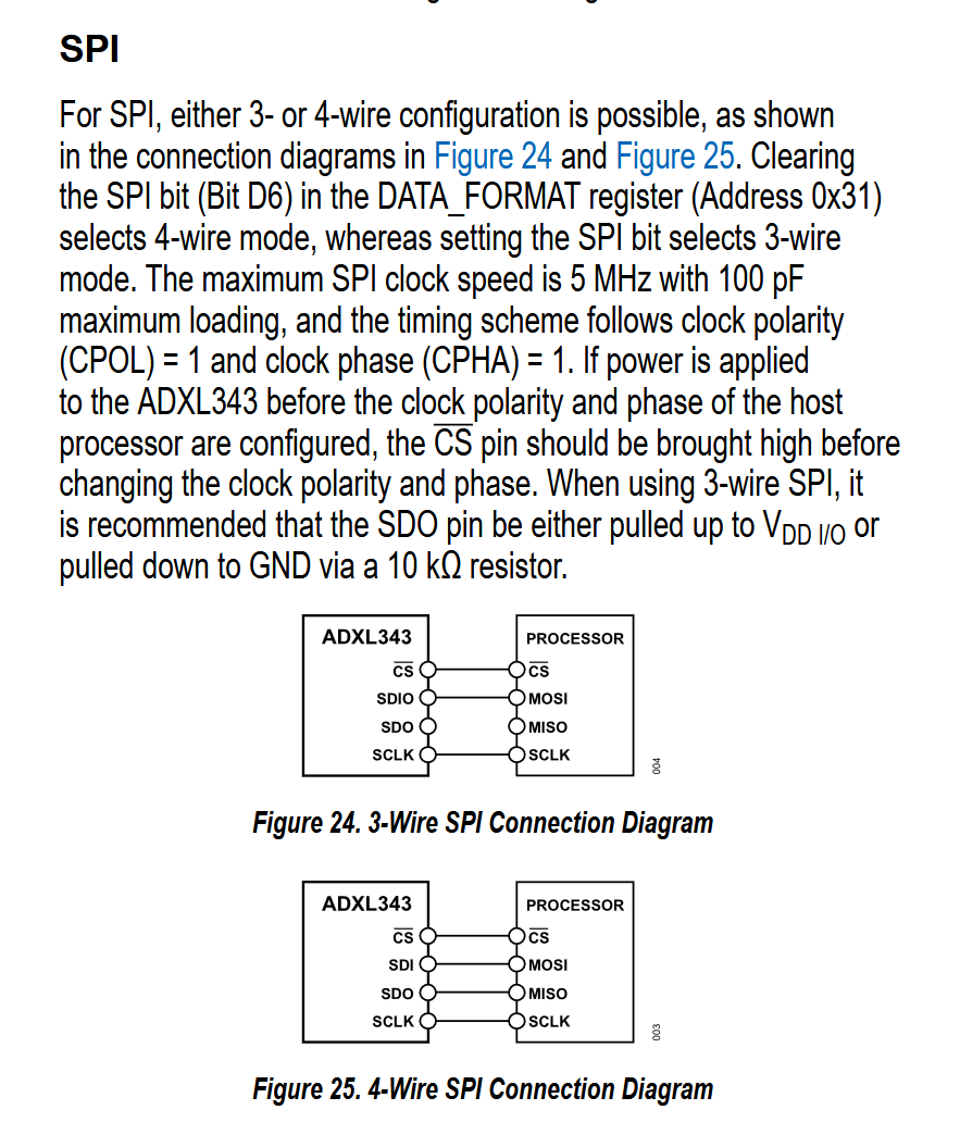
Initially I followed the 3 wire setup for my PCB. 3 wires is easier than 4, right? WRONG. IT NEEDED 4 WIRES.

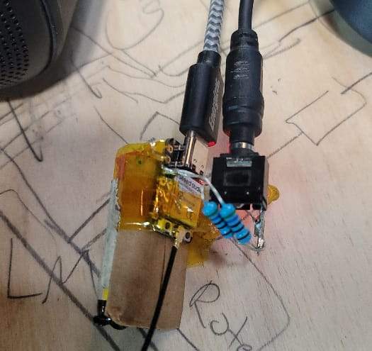
For the record, this is the final wiring. MUCH more complicated than the inital diagram
My ESP32C3 couldn’t even read anything! Thats because it needed resistors.
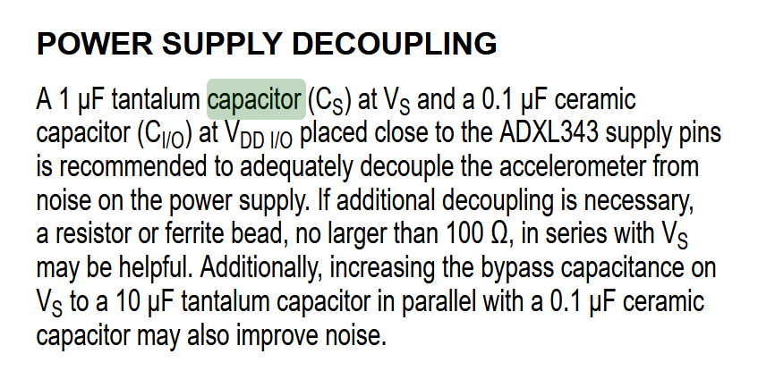
Next up, my ESP32C3 kept shutting itself off. This was to protect itself, It needed capacitors.
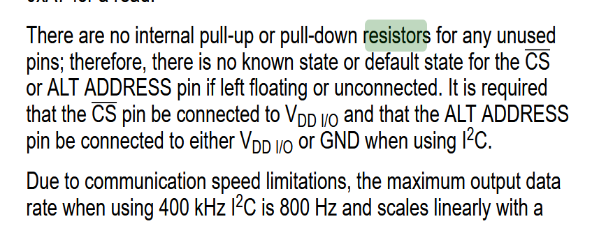
In the end I used a similar set up to this. I learned that Vs and Vdd AND CS ALL needed to be connected to the 3V3 pin.
MAC Address
I using the guide, I got code for both the sender and receiver of the ESP32C3. I copied and pasted the provided instructions. I ran into some issues.
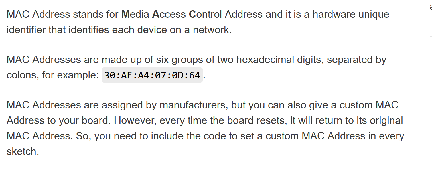
The easiest part was getting the MAC address. ONLY the sender needs the address of the receiver. It is possible to change the MAC address of a chip. I followed the instructions from RandomNerdTutorials. If you run the code and open up your Serial Monitor, it will show you the address.
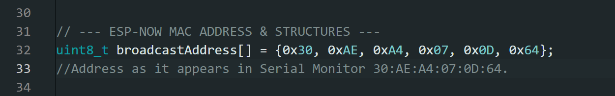
You need to add the “0x” in front of every 2 character sequence. I made the silly mistake of giving the sender its own MAC address, make sure to label which address belongs to which controller!
Sender
I copied and pasted the exact code provided on the website. It did not worked. I used LM Studio to run Gemma 4 E4B Instruct. I gave the AI all the context and kept copy/pasting the error messages until it worked.
Part of the reason it didn’t work was outdated libraries. Luckily, the error messages said exactly the format it wanted the new code to be in.
Another problem is that for some reason the code that kept generating had sections to simulate movement. This made me very confused and I deleted all those lines.
I generated code that sends the words “movement detected” when the ADXL343 sense movement, and it sends “movement subsided” when it sense no movement.
More specifically it works in relation to the last datapoints.
| relationship | message sent |
|---|---|
| 2 similar coordinates | movement subsided |
| 2 different coordinates | movement detected |
It also specifically sends the message if its gone from a moving state to a still state, and a still state to a movement state. The relationship between these two things had to specifically coded.
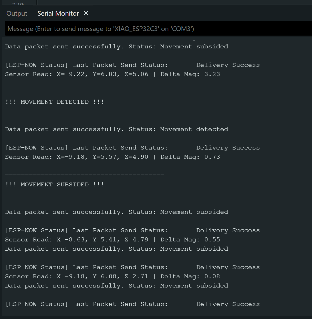
A successful code will show this in the serial monitor. You will also get a different message if the message was sent successfully, but not received. THis allows you to know if the problem is from your sender or your receiver.
Reciever
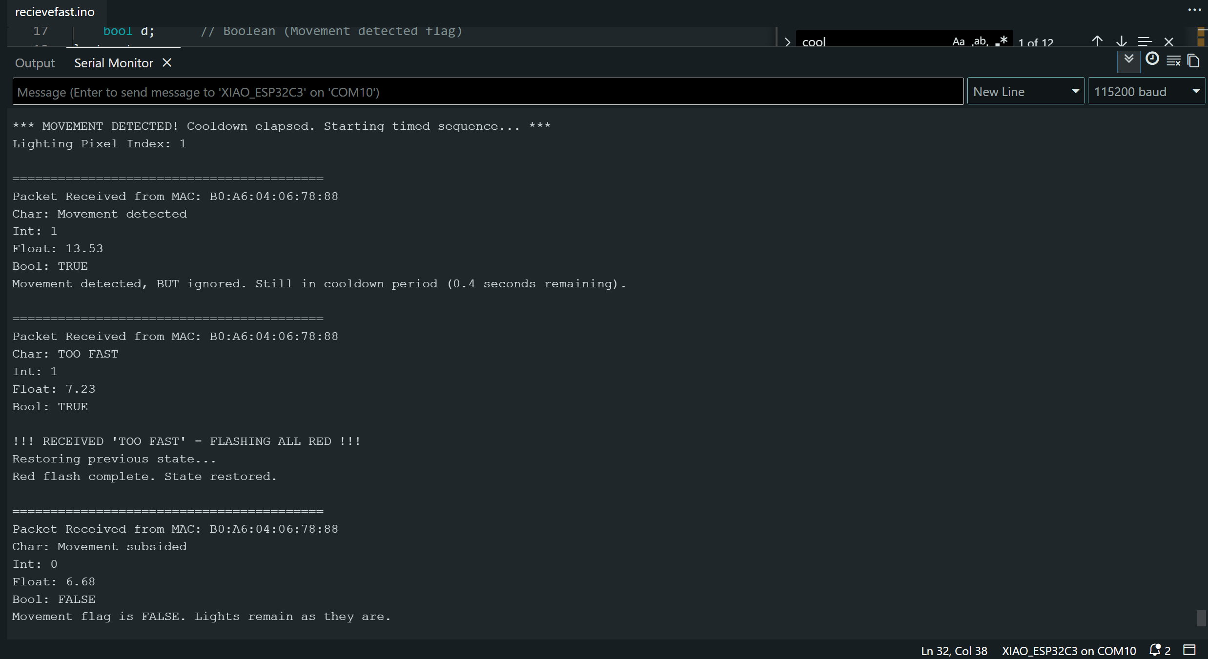
Successful reciever code looks like this in the serial monitor. I ran into many of the same problems as I did with the sender code regarding the outdated libraries and code. Initially I generated code that turned on all lights when the message “movement detected” was received. The receiver DOES NOT received any movement coordinates, only the words “movement detected” or “movement subsided”.
My first code turned on the lights when the messages “movement detected” was received, but did not turn off the lights when the message “movement subsided” was received. All conversations with Gemma AI are in my files at the end of the page.
One last troubleshooting note!! At the very end I had run all the diagnostics I could for why the ESP32C3 were not communicating after they were working before. THey were just too far apart. Also, use the provided Antenna, but DO NOT attach them while the ESP is on. It might damage it.