Week 12: Mechanical Design and Machine Design
IN PROGRESS
group assignment: • Design a machine that includes mechanism + actuation + automation + application • Build the mechanical parts and operate it manually • Actuate and automate your machine • Document!!
FAB NODA PRESENTS: BIRDPECK
Video Link: Birdpeck
Documentation
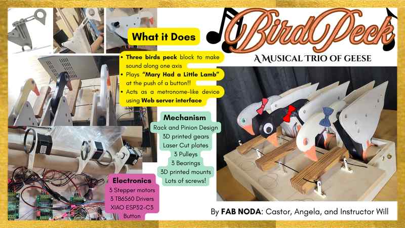
At Fab NODA, we are made up of two students and we’re both brand new to the world of digital fabrication. So, we decided to make a machine called “BirdPeck” that would be a set of three birds striking a wooden block to produce sound. The machine would play a tune (Mary Had a Little Lamb) and could also operate in a metronome-like capacity through a local Web Server that allows for speed, acceleration, and motion control of each motor.
Team Work Flow
Our team is Castor, angela, and our instructor Will. After meeting together to plan our project, Castor took on mechanical design, laser cutting, 3D printing, and video production whereas angela focused on electronics, programming, automation, actuation, overall documentation, and slidedeck. We worked together on assembly and testing. We had Will’s help and guidance along the way. As new ideas sparked along the way in the process of making, we made sure to communicate together. We worked in parallel and each of our focus aligned well for what needed to work on to complete our final project ideas. We also worked together during key integration steps, like linking up the stepper motor with the pulley system and matching speed/acceleration of motor in a way that aligns with the design evolutions of the striking bird head. We communicated pretty much daily and made use of our shared folder for sharing design files and code.
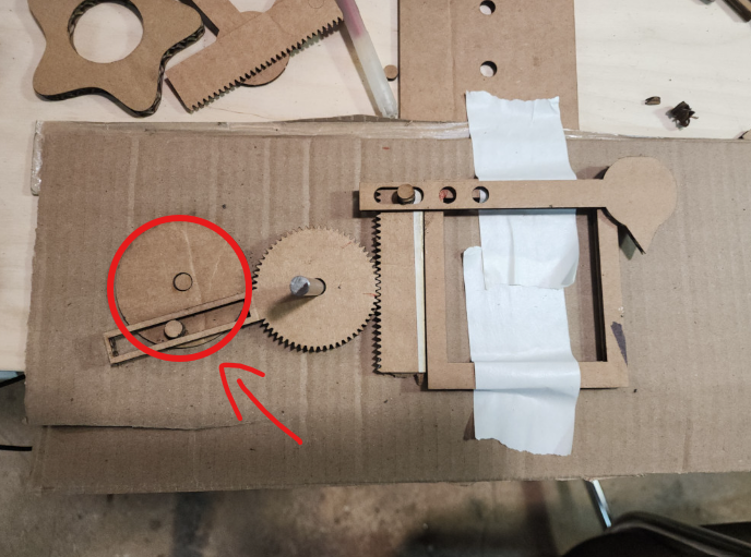
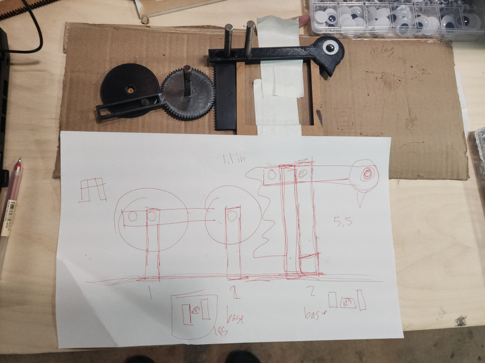
Cardboard Prototype
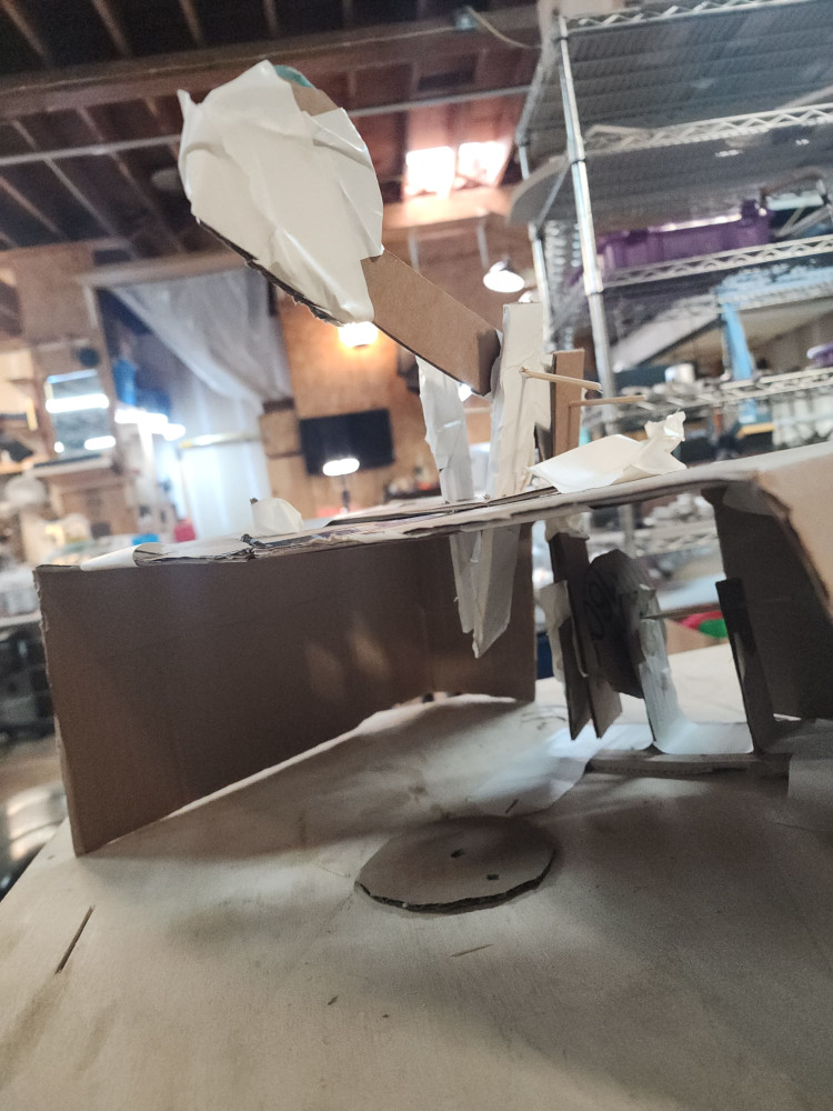
On day 1 I jumped straight into prototyping! I used cardboard,scissors, and tape to freehand an inital design. I was unable to describe to my classmates what I was imagining the mechanisim to be, so I made it! From this prototype I understood that I needed 3 main pieces to work
Laser Cutting
I started out with this design on FREECAD. At the time, my 3D modeling skills were based on my ability to make an SVG and extrude. This design is made of 5 parts, 3 of which move.
On the suggestins of the lovely instructors from Global Open Time, I changed my design from a series of rectangles connected by holes to do a rack and pinion deisgn. I used an extension on FREECAD called gear workbenck to create the gears. I created all the pieces as an SVG that I extruded to check fit.
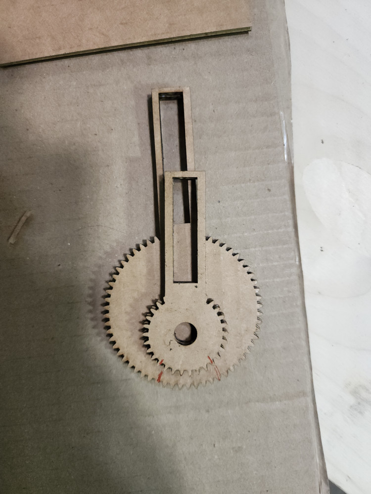
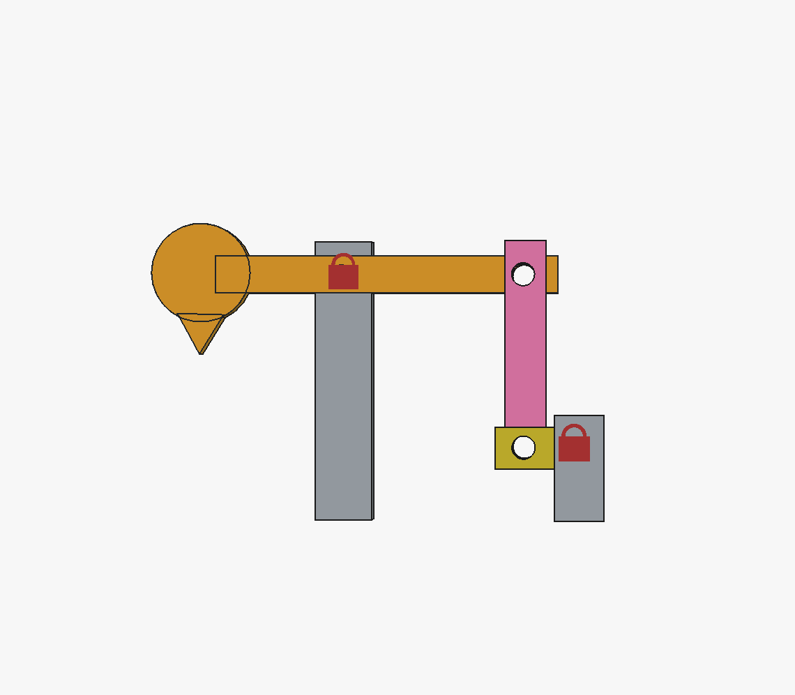
Trying to figure out the correct size ratio of the great to the rack was tough, especially figuring out the placement of the hole. In my initial tries, making the gear itself bigger or smaller didn’t change the distance traveled much. The red lines on both of these pieces mark the two extremes it would touch the rack.
They key was actually to make this piece bigger!
3D Printing
Once I got it all set up we sent it to the 3D printer! We had to go through many iterations to get the tolerences to slide correctly against each other. These pieces were made with PETG filiment. Once we verifies that all these pieces fit together we had to create a structure to make it upright!
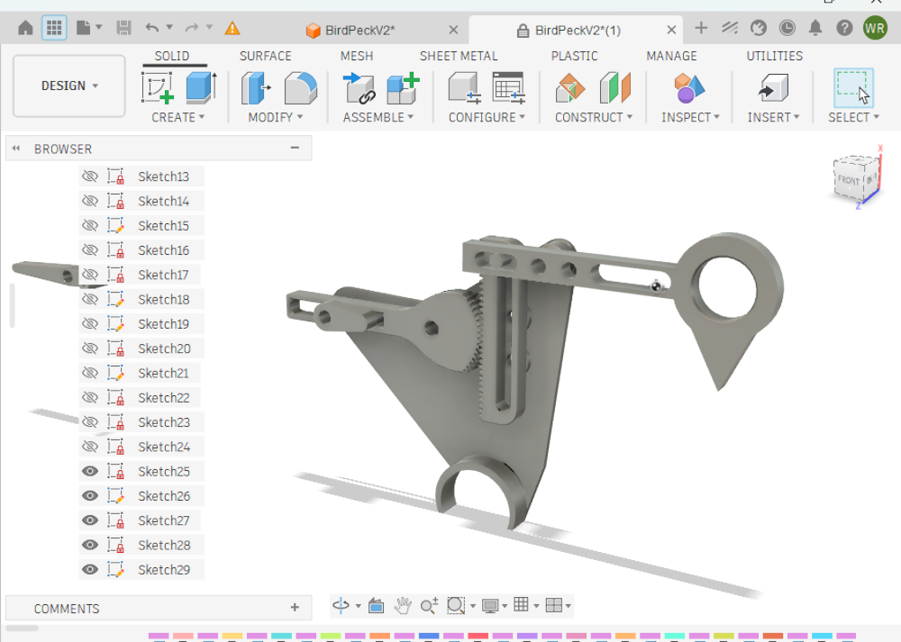
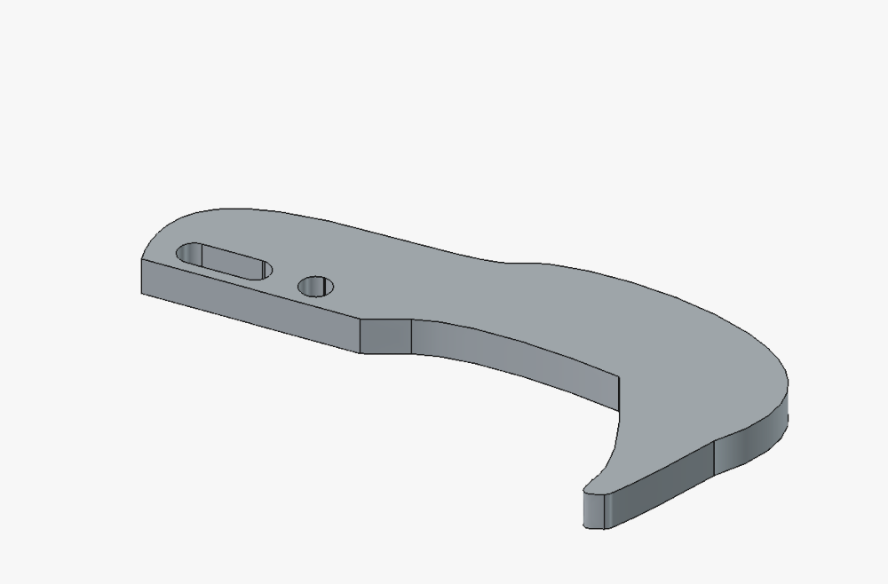
This next iteration you can see that improvements made. This is the design the Instructor refined. He streamlines the shapes to be smaller and more easily printable. This is a very important part of the prototyping, as it allows us to get through iterations quicker.
- the head is more hollow
- the turning circle has been compltly reduced to a round ovalish shape,
- the gear itself isnt printed all the way around, it only has teeth where it will interact with thte rack
- the rack now has a hole in the middle that we can anchor to the sides
- theres now a supporting structure that we can press 6mm bars into to assemble!
Here’s how it looks printed!
Aesthetics
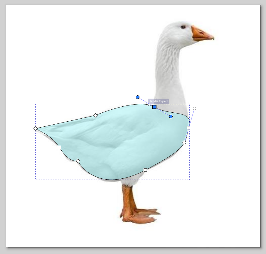
Aesthetics easily added about 5 more hours of work to this project, but it was worth it. We originally tried a woodpecker, or a duck. But the ratios weren’t looking right. So instead we modled it off a goose, because the long neck fit our design! I used Inkscape and traced out a design, then I overlaid it with the structure to line up the holes from the 3D printed supports.
Next I laser cut the bodies out of 1/8th in plywood and painted them. This had a functional purpose. The nails and pressure of the belt from the motor were pulling at the 3D printed structure, so we reinforced it with plywood!
Next up was the goose head. Again, I traced over the model. I made sure to overlay it with our current bird head design to make sure that the hols and the peckers were in the exact same spot.
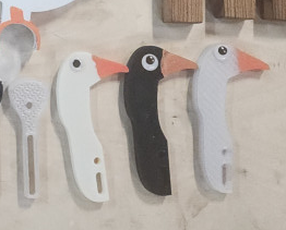
And this is the fun part! We were on a time crunch and used all 3 3D printers, but we didn’t have 3 spools of filiment. That is why the heads and bodies are different colors. I painted the beaks on each of them, and then we all got to pick what eyes to put on our goose!
Xylophone
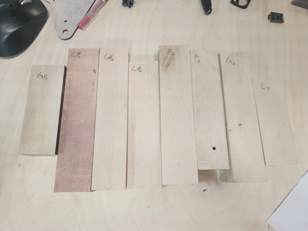
Will expirimented with xylophone keys. We used La Favre to guide us. These were cut out with the CNC. after some expirmenentation and reading we learned that keys like to be twice as wide as they are tall, and that if the height and width were the same, height determined the notes. In this picture I used an turning website to determine each note.
After the right keys were picked out ( F, G, A) I sanded and finished the keys.
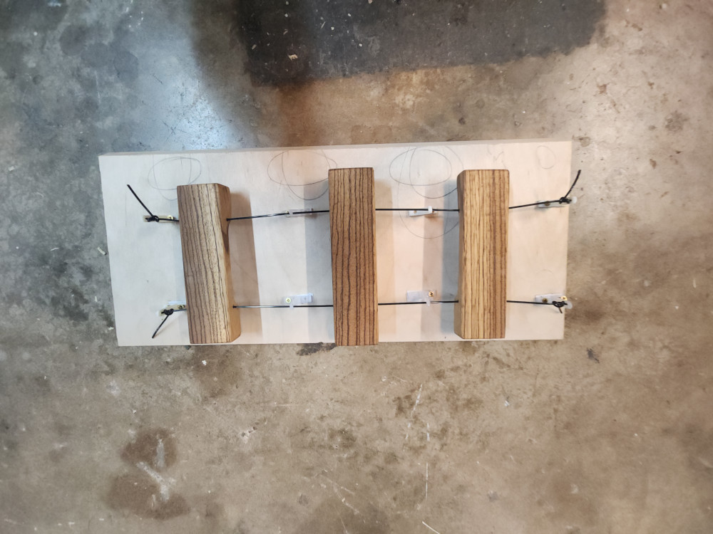
We also tested 3 different methods to see which one would produce the cleanest sound
- hanging on a string
- using rubber pins
- laying on styrofoam.
Hanging by a string produced the cleanest sound, and by far was the easiest to mount
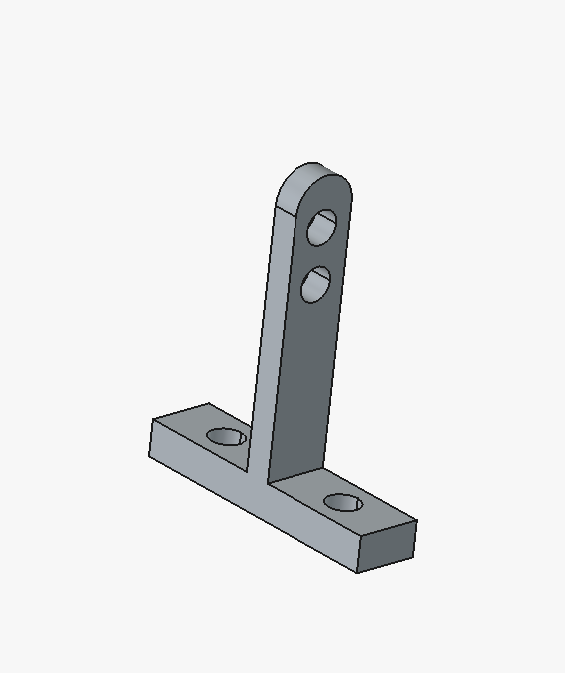
I went into FREECAD to create a simple tool to string the keys through and keep them suspended.
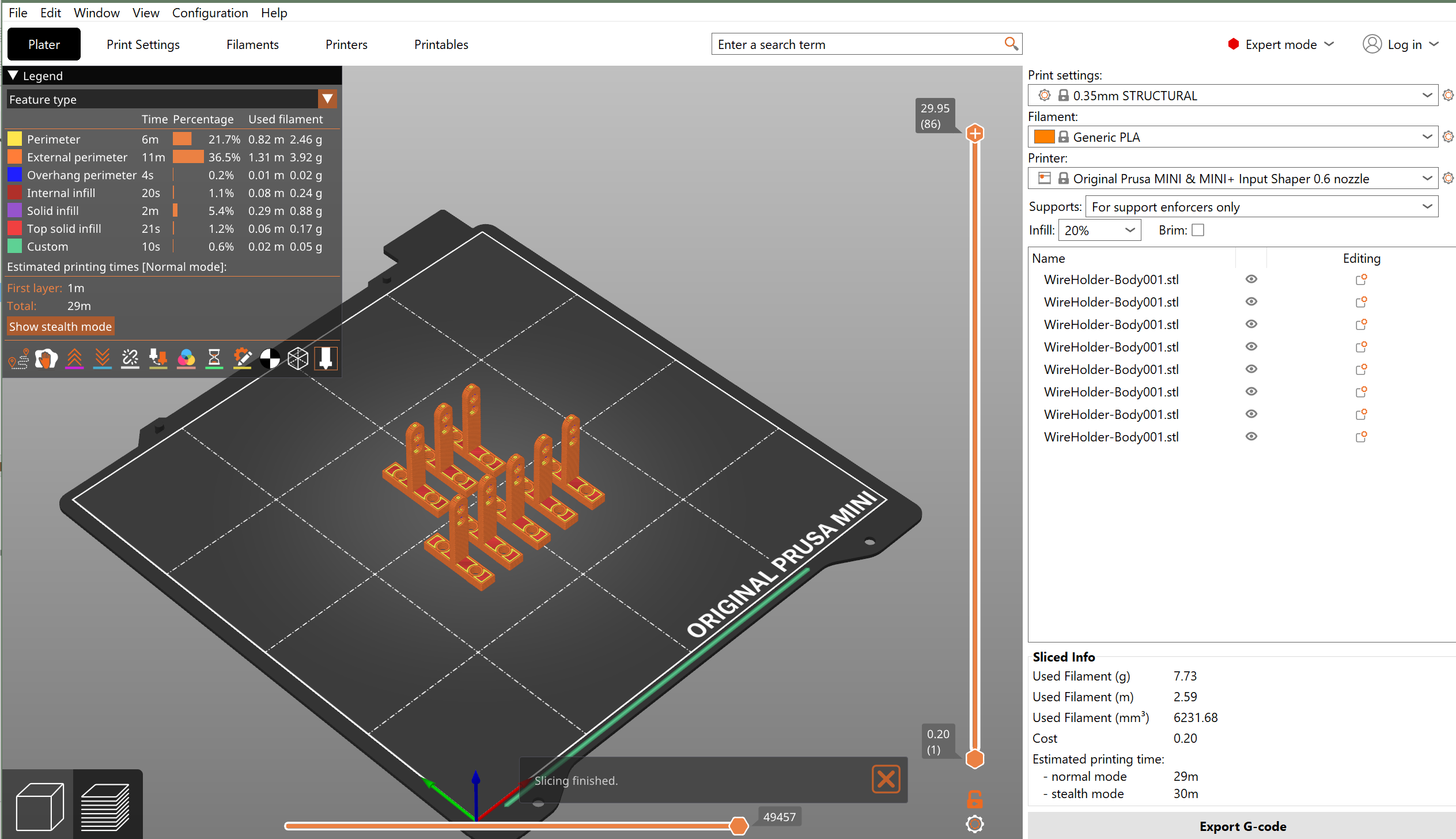
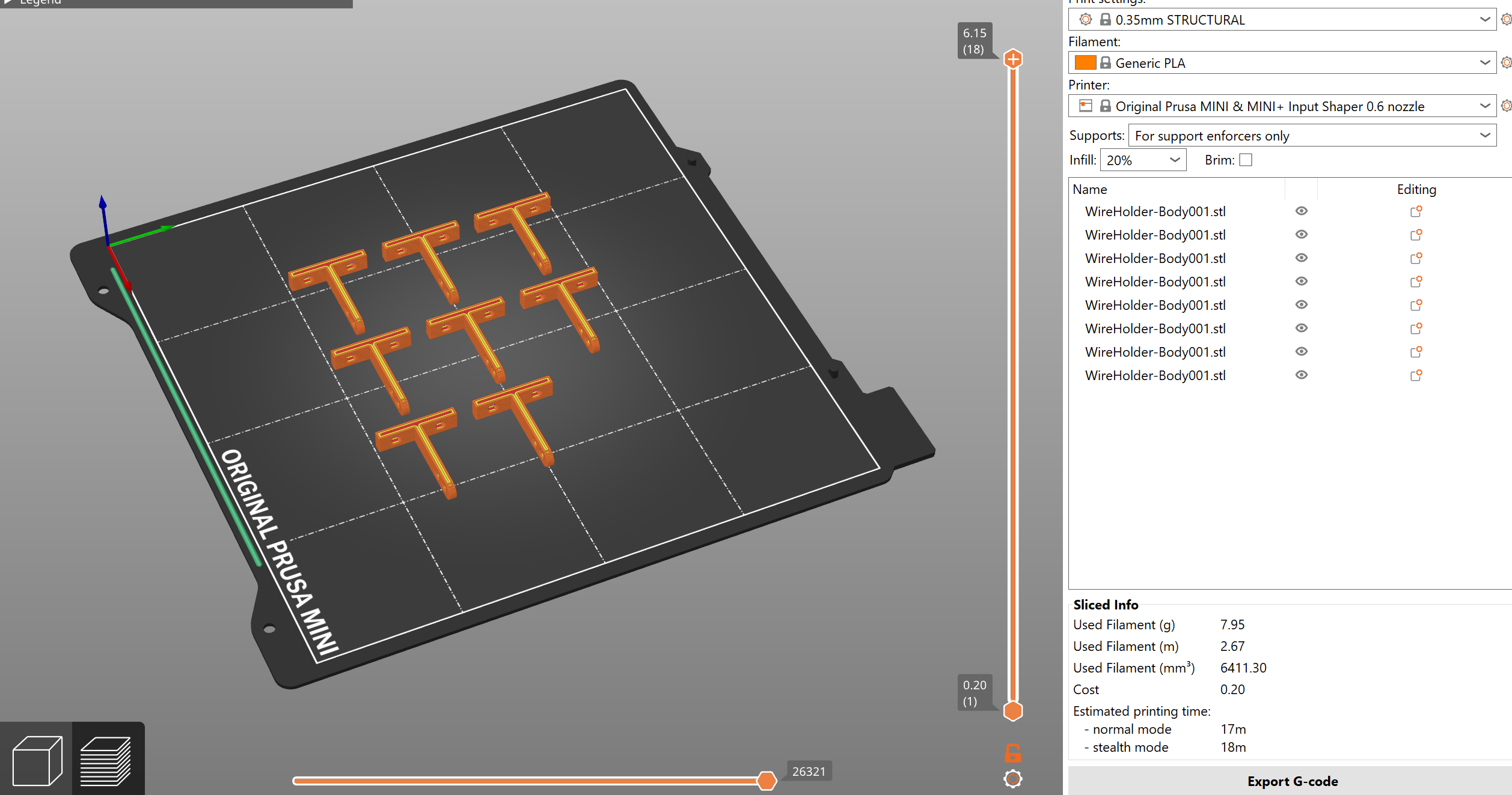
At this point, we were so close to being done. My iterations of this suspender were taking longer than I thought it should. I realized it was the orientation that I was printing them on. Laying them on their side reduces the printing time by half!
Machine and Mechanism Building
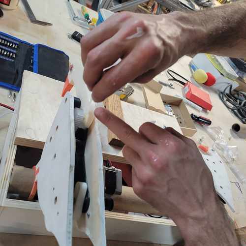
Once we had all of our parts – we worked on assembly.
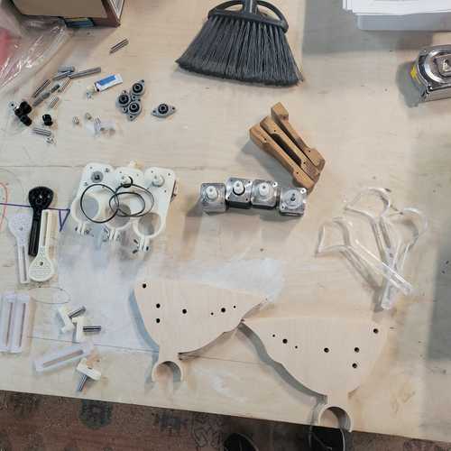
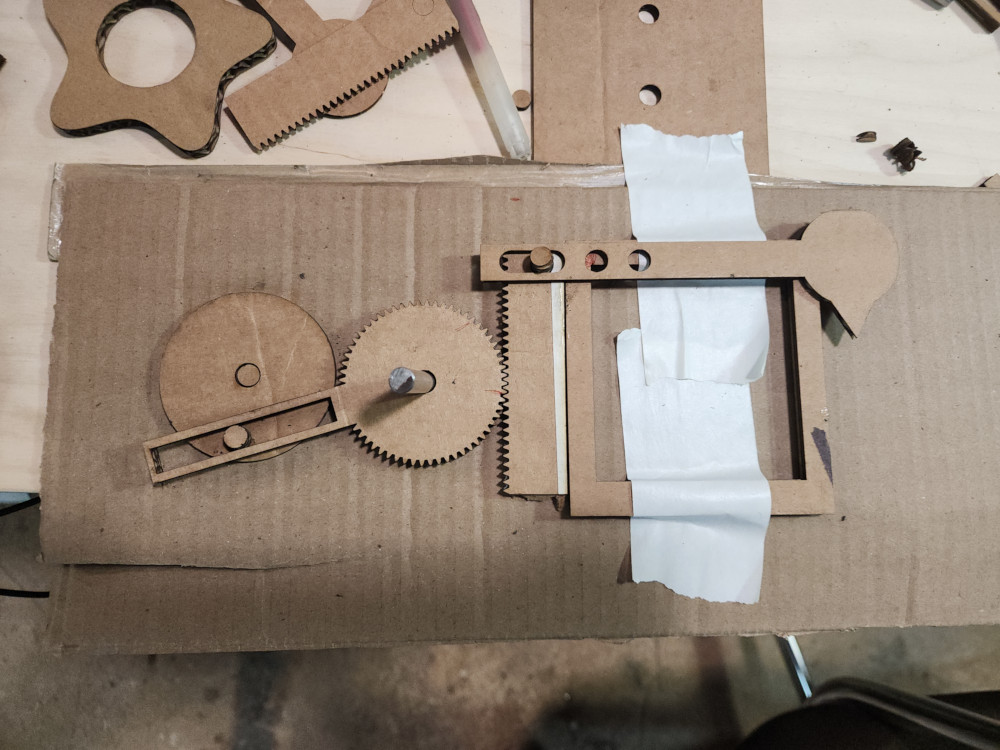
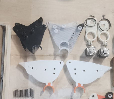
Layout of our parts for assembly
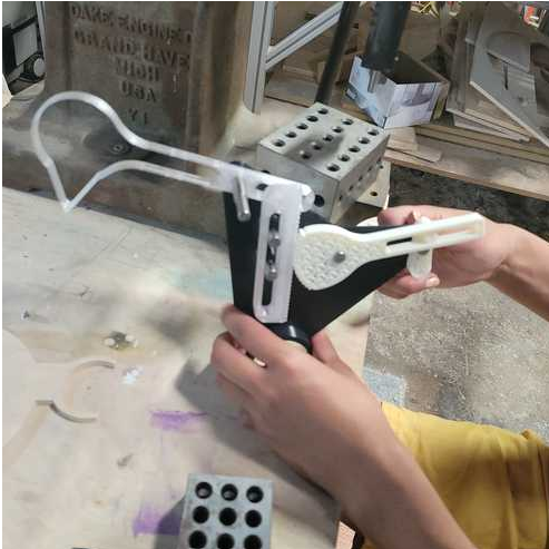
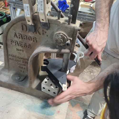
We started assembly by pressing pins in using a Dake Arbor press which we have in the lab. This presses with 2 tons of force by the way! Taking three pins and one of the side panels, we set up everything on 123 blocks which are fixturing blocks with holes that allow for pressing the pins through. This method keeps everything aligned which is very important for correct operation of the mechanism.
After pins are pressed into the plate, next assembled are the bird head, rack and pinon and other components that make up the overall mechanism.
The basic mechanism of the bird pecker.
Then align the second plate and use the arbor press again to press in the pins to this second plate. This could be done by hand if needed too.
Pressing in second plate with arbor press
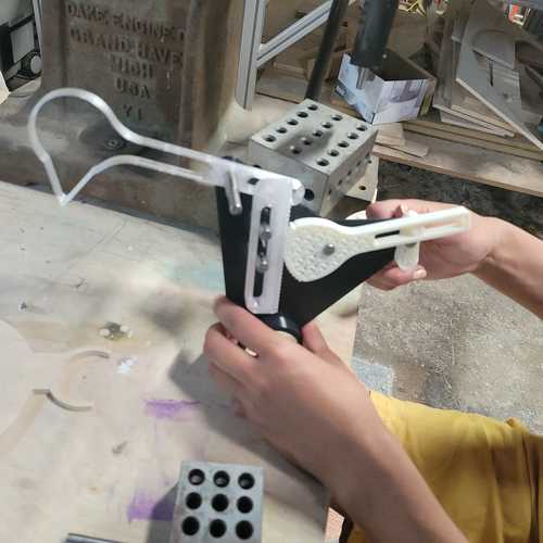
Next, we can place the wooden side plates of the bird. Pressing it in through the pin, place the bearing screw it down and place pulley head over that.
For fixturing the motors we put mounted the stepper motors on a 3D-printed mount using an M3 screws whcih go ito their face. This is then place on a cardborad tube in between where our birds will be mounted and tightened using a wingnut.
Stepper motors mounted
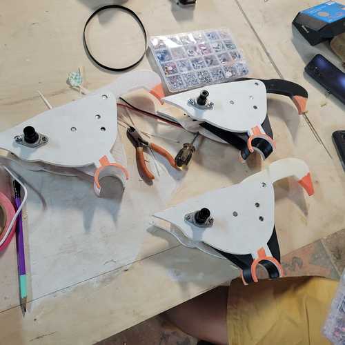
Assembled birds
After motors were mounted we mounted the birds. Also strung the wooden striking blocks.Ready to test operation!
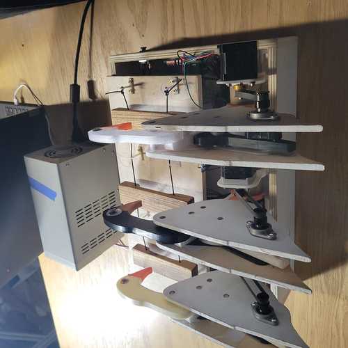
View from the back of our final bird peck machine
Actuation and Automation
Along the process of machine and mechanism building, we spent time figuring out the electronics, software, and automation that would run the machine.
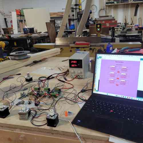
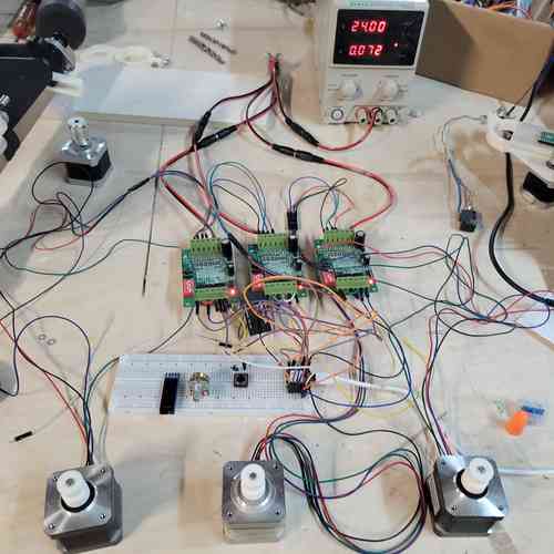
We used a XIAO ESP32-C3 board placed in a custom made PCB. We used 3 TB6560 stepper motor drivers. We wired to power supply at 24V for the motors and used the USB for logic at 3.3V.
We also had a local web server from the ESP32 which controlled speed, acceleration, and motor motion. In this way, the machine could act in a metronome-like capacity. We wired a push-button on the side of the machine which automated the machine to play “Mary Had a Little Lamb” on the blocks.
Stepper Motor Operation
After many hours of testing various DC motors, encoders, and motor driver boards, we ended up using a stepper motor with the TB6560 Stepper Motor Driver board. Here is a tutorial on TB6560 Stepper Motor Driver boards referenced . Also, Will shared this library by MobaTools made for model railroader enthusiasts which had code for stepper motors.
Web Server Interface
We learned how to control a stepper motor through a web server via the ESP32 chip. Eventually, Will shared more code from the MobaTools library that had an ESP32-Web example. It took some German to English translation but this was the basis of code used for hosting the webserver which proved extremely helpful for operating each motor during testing.
Video of operating a stepper motor hooked up to bird pecker using a slow and fast speed. Very cool that you can interface on the web!!
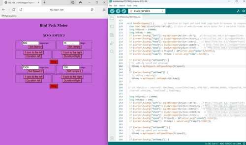
Making progress in the weeds of late night coding. At this point, I figured out how to add a second set of inputs for a second motor and separated it so that the top inputs apply to motor 1 and the bottom apply to motor 2. After a little more testing, I’ll apply the same logic to create a third set of inputs for the final motor
Motor set up using web server after updating code to include third motor
Automation
After the stepper motors were reliably running with the web server interace, we next added to the void loop a function for playing the “Mary Had a Little Lamb” tune when a button is pressed. After testing different functions and timing using delay and speed/ramp length times, we found a good code.
Three motors set up to Web Server and with button. Running motors to the tune of Mary Had a Little Lamb
Electronics Production and Wire Management
Designed and made a circuit board for mounting the Ziao and wiring motors. Theres just enough pins to wire all three stepper motors and have I2C lines open (though for this assignment we’ll just wire a button on one of those pins). After milling and soldering, we rewired the stepper motor drivers and button.
We used power supply equipment for motor drivers supply at 24V and a USB cable to power the XIAO board. To access these cords we needed to cut a hole in the base box to feed the wires through.
We also had this push button switch with screw terminals in the lab which is used in places like elevators. You can wire it by simply placing the wire underneath the screw before tightening it.
After wiring everything up, all the motors ran smoothly on the first attempt. Eventually, I got some zip ties an tape for managing wires and fixutred the motors and PCB board into place.
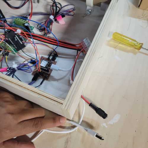
Creating an access hole for wires
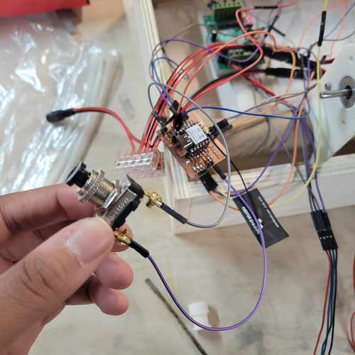
Fastronix Momentary Push Button Switch. Wired to the ground pins and pin D5 on the XIAO board.

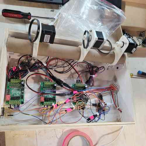
A look under the hood. Tidied up the wires
Troubleshooting and Problem-Solving
Below are some of the problems we ran into as a team and how we solved them:
Mechanism Breakdown
After our first round of assembly, for first attempt to run the machine only one of the birds worked smoothly. We decided to switch out the plastic gears on the stepper motors for metal ones and we greased the gears inside the bird with with silicone grease. We also just used the Web Server Interface to run the motors so the parts could wear in.
Adding in grease to the gears
After making these changes the bird ran much more smoothly.
Screws falling out! During one of our early build iterations, the screws started falling out of the bird side panels while angela was testing code and motor operation once assembled. This was because the earlier iteration of the side panels was not long enough for the bearing to be drilled in on both sides. To fix this Castor redesigned the side panels to be longer, and used his artistic skills to make it look more like a goose. This worked perfectly to drill in both ends of bearings.
DC motor + Encoder struggles When testing with DC motors, we learned a lot, but ran into struggles with getting them to the precision of speed and motion control desired. We tried using an encoder which worked within certain ranges but eventually we decided to move to stepper motors for easier control of position and acceleration.
Possible Improvements
Some possible improvements for our machine include:
- We could test using different striking blocks or other material for producing different kinds of sounds
- We could simplify the design of the mechanism by translating the motion more directly
Design Files
Find a link to our design files here