System Integration
Introduction
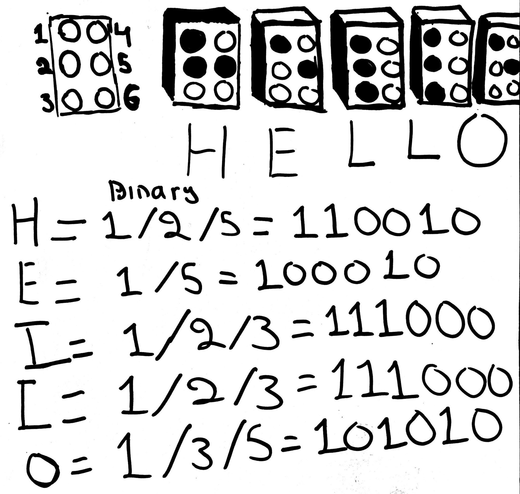
Braille allows letters or numbers to be represented through combinations of six dots, which allow us to identify which ones must be raised to represent a specific letter. The idea proposes using a six-bit binary representation, in which each bit corresponds to one of the six dots in the Braille cell (0/1).
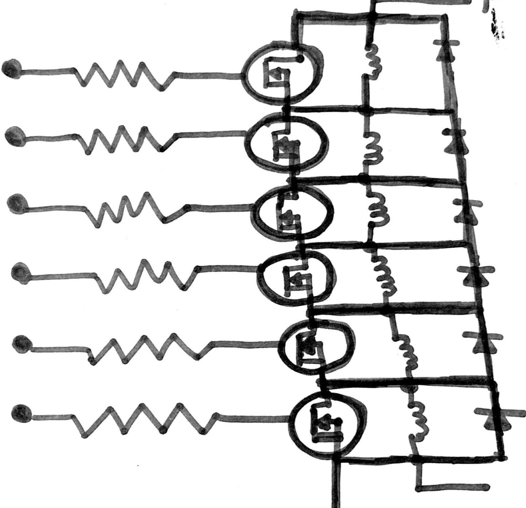
On the other hand, one of the challenges is the development of a control mechanism that allows solenoids to be used to activate each Braille dot individually. However, during functional testing, the solenoids overheated. One proposed solution was to implement a control circuit based on MOSFET transistors, protection diodes, and modulation, with the aim of regulating the energy supplied to the solenoids. However, this alternative increased the complexity of the design and implementation of the system (engineering trade-off).
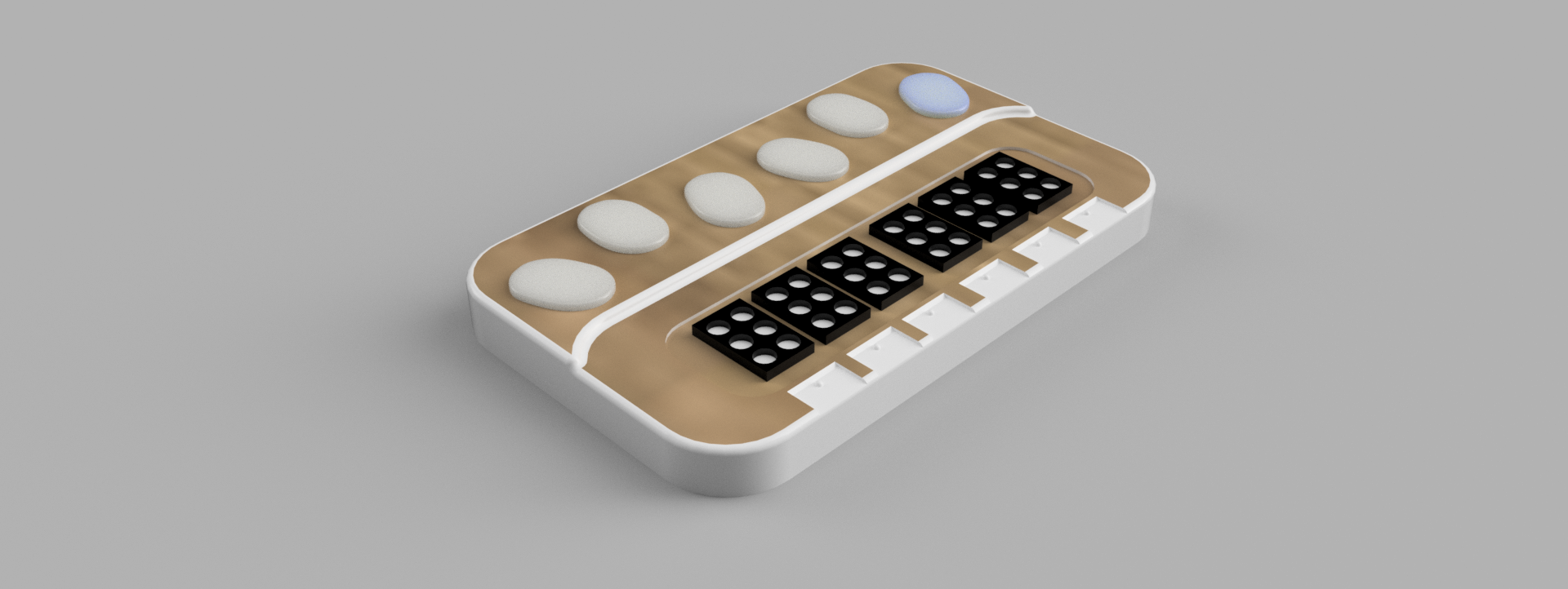
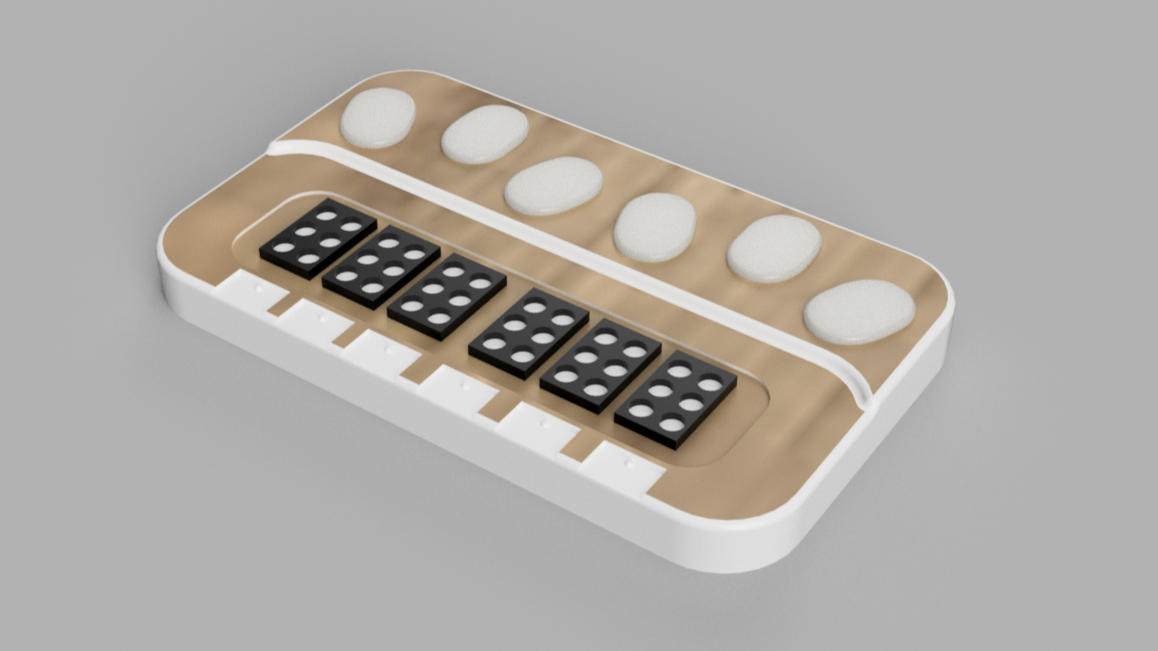
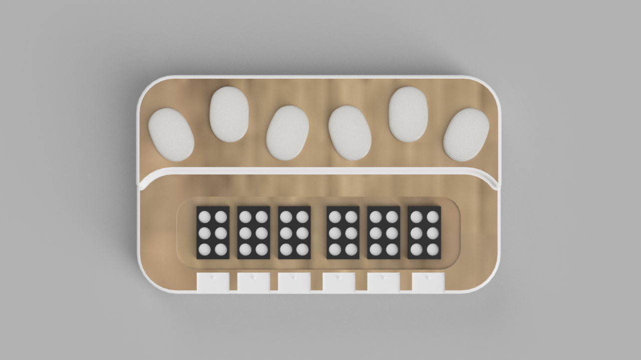
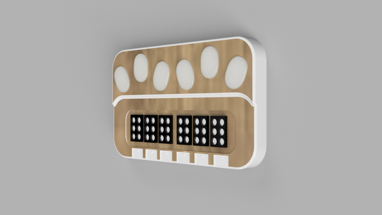
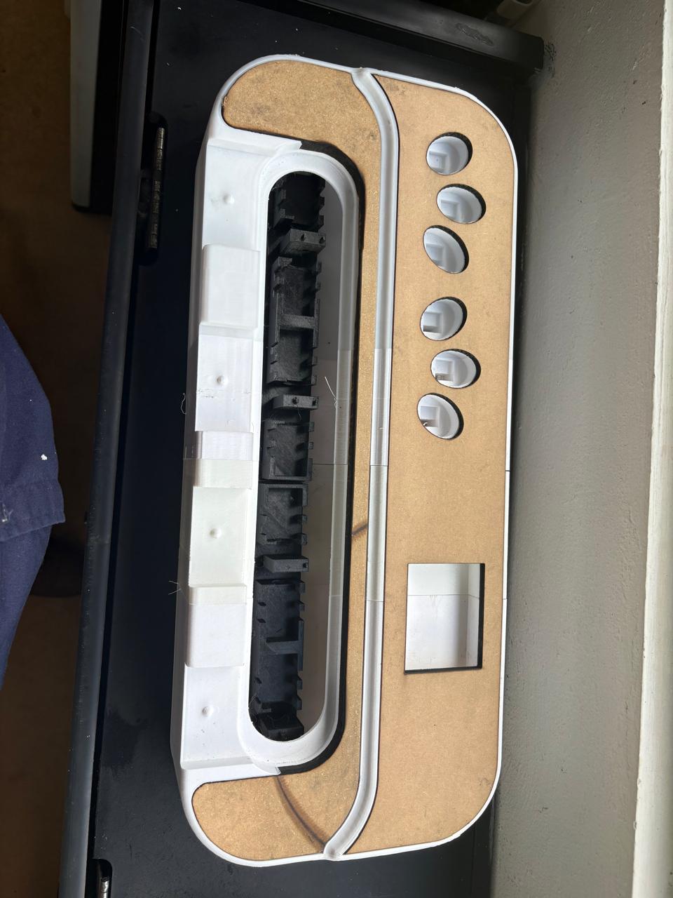
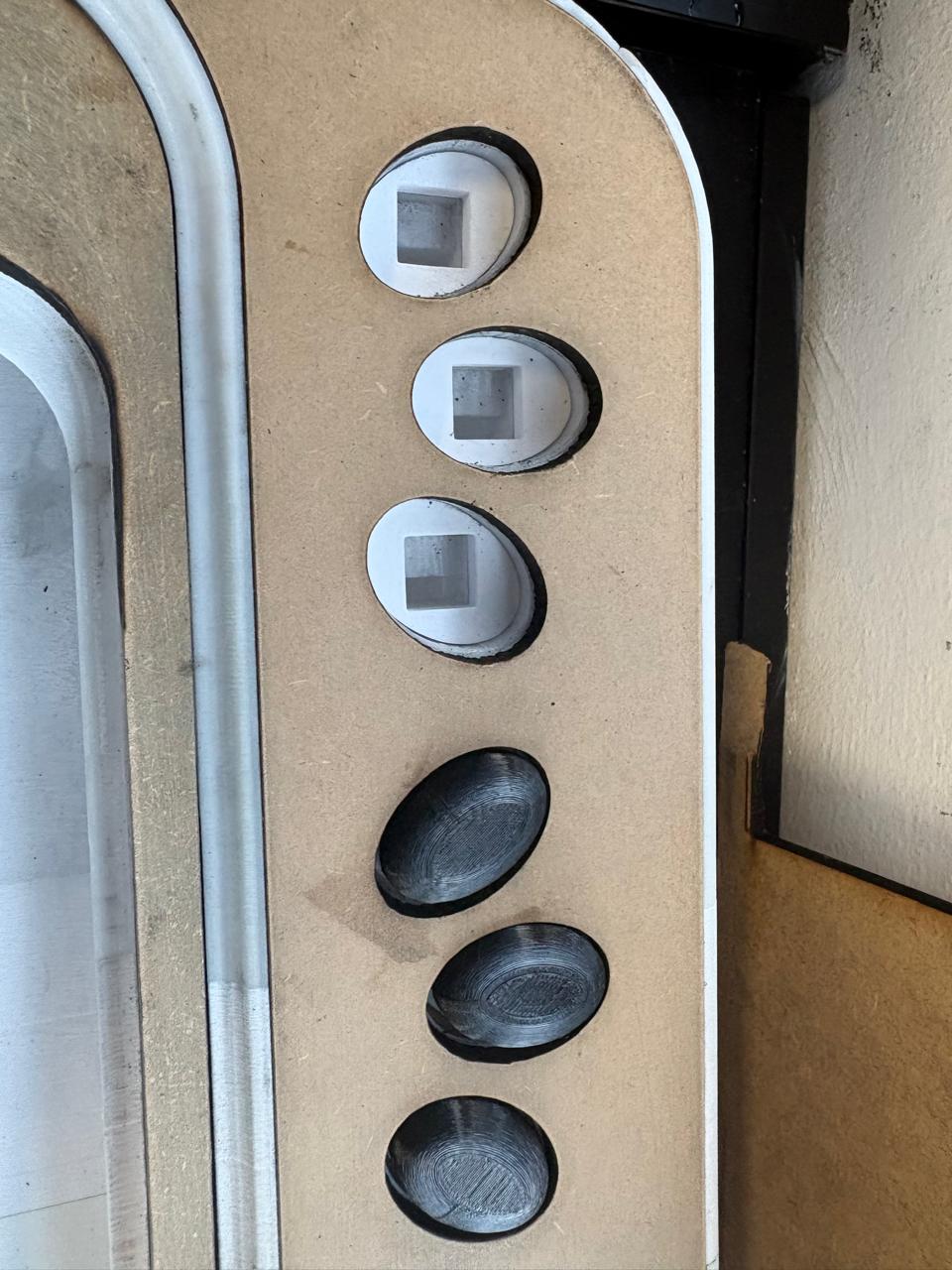
The preliminary design of the device includes six buttons for writing in Braille and cells to represent the characters entered by the user. This proposal is a first approximation to the physical structure of the device.
Integration Testing
We used a transient analysis as a preliminary test of a control circuit to check whether it was possible to regulate the flow of current to an electrical load using a pulse signal and thus analyze the periodic activation and deactivation of the current as a first approximation to the solenoid control system.
A 3.3 V control signal with a period of 200 ms and an activation time of 100 ms was used. This is equivalent to a 50% duty cycle. The circuit included a 3 V power supply and a 6 Ω resistor. During load activation the current reached approximately 500 mA.

We also used an MCP23017 because the XIAO has a limited number of output pins to control multiple solenoids simultaneously.
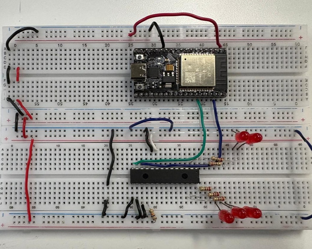
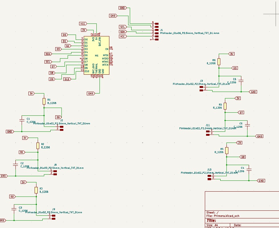
An electronic schematic was then developed in Autodesk Fusion as a control stage for the solenoids to activate each one individually using control signals.

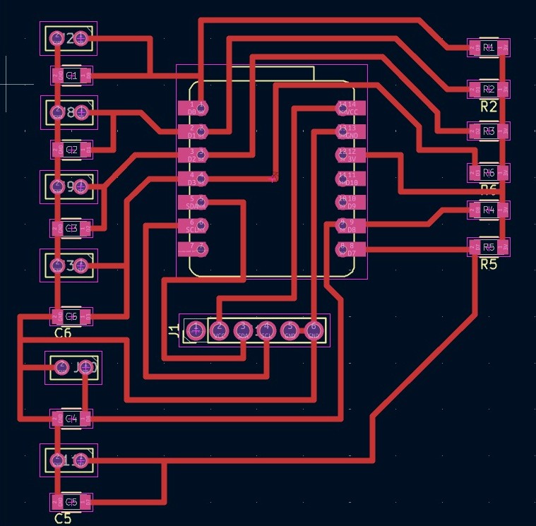
But the implementation of the PCB was a disaster. The routing of the traces in Autodesk Fusion was not optimal despite the tests carried out for the development of the circuit.


We switched to KiCad to have more control over the circuit design and routing of the PCB traces.
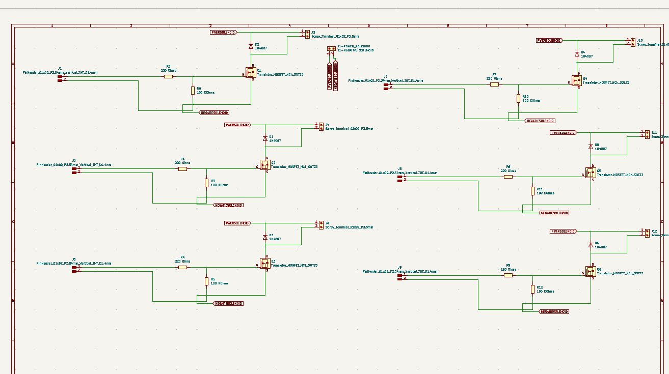
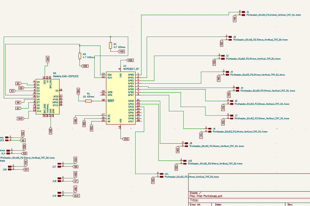
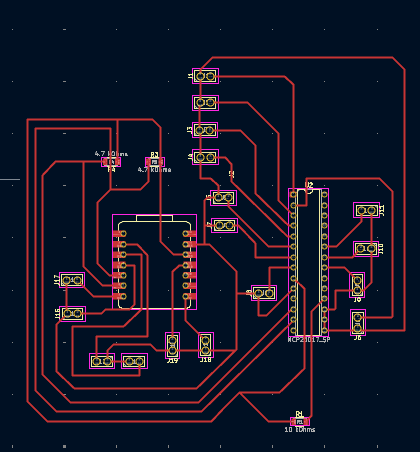
The preliminary system consisted of two stages. The first consisted of a motherboard responsible for receiving the signals from the buttons and generating the control signals for the solenoids using the XIAO and the MCP23017. The second stage corresponded to the electronic conditioning circuit to control the individual activation of the solenoids.
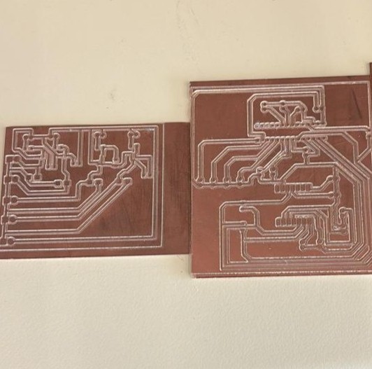
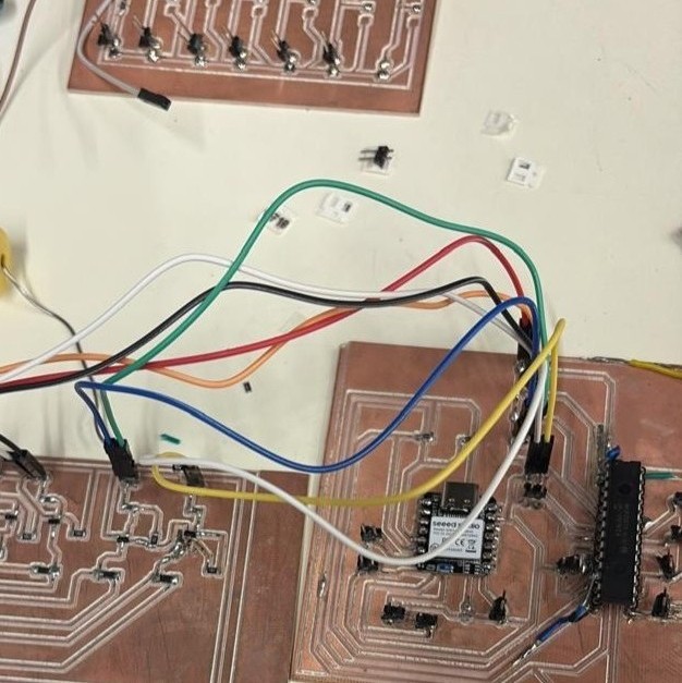
Although the initial approach was technically feasible, an overengineering problem was identified during the implementation tests. We re-analyzed the problem and the project to find a more efficient solution.
So we replaced the solenoid-based solution with a mechanism that would allow us to generate different physical combinations to represent Braille characters.
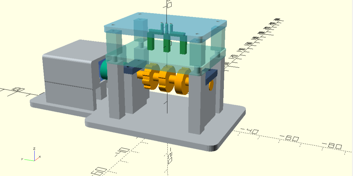
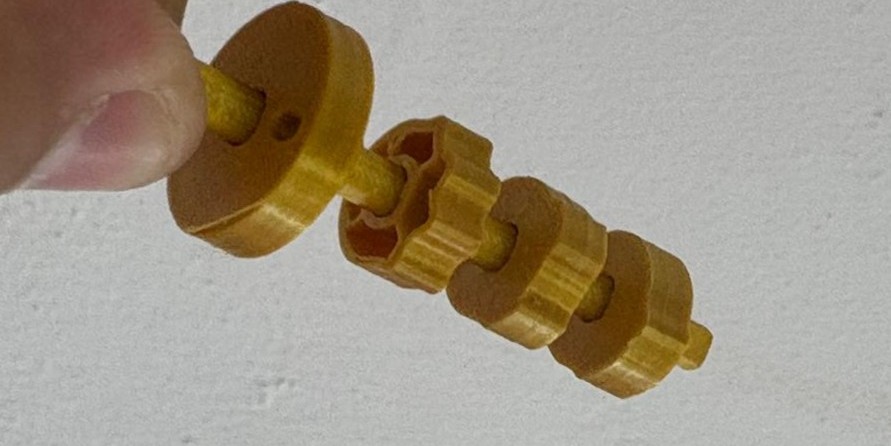
System Layout and Design
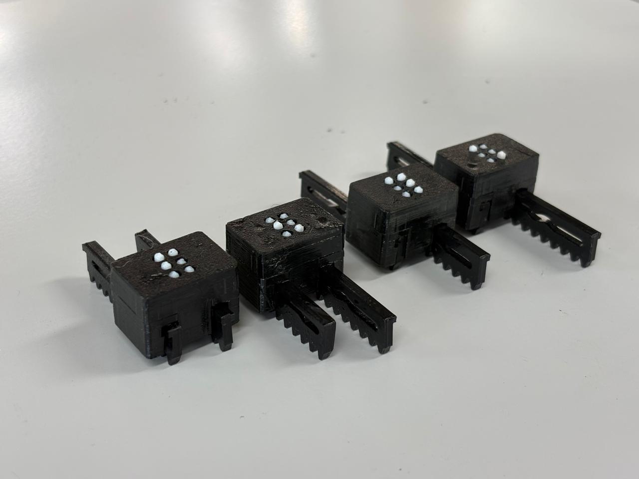
After iterating on the design, the proposal for the Braille cell was based on a rack-and-pinion mechanism with toothed components that move linearly to generate different physical combinations of the six Braille dots.
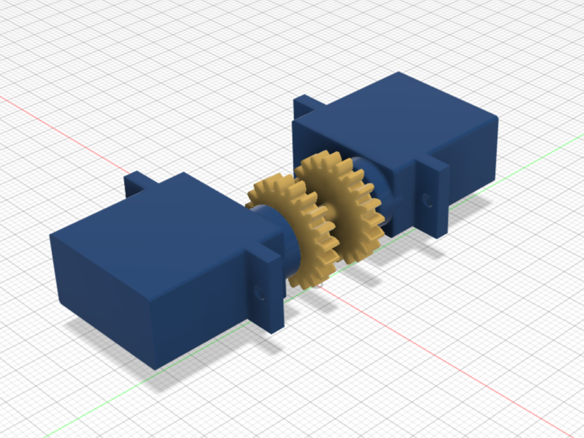
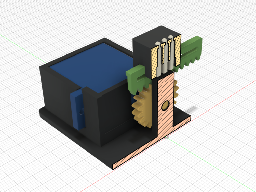
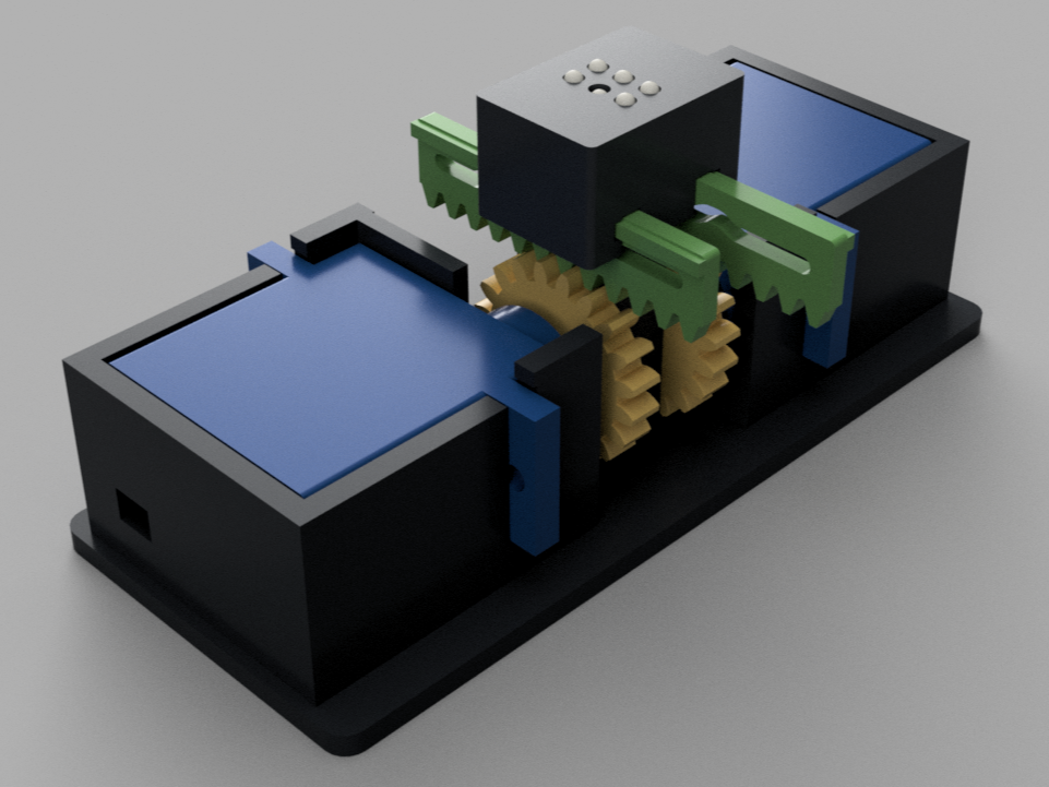
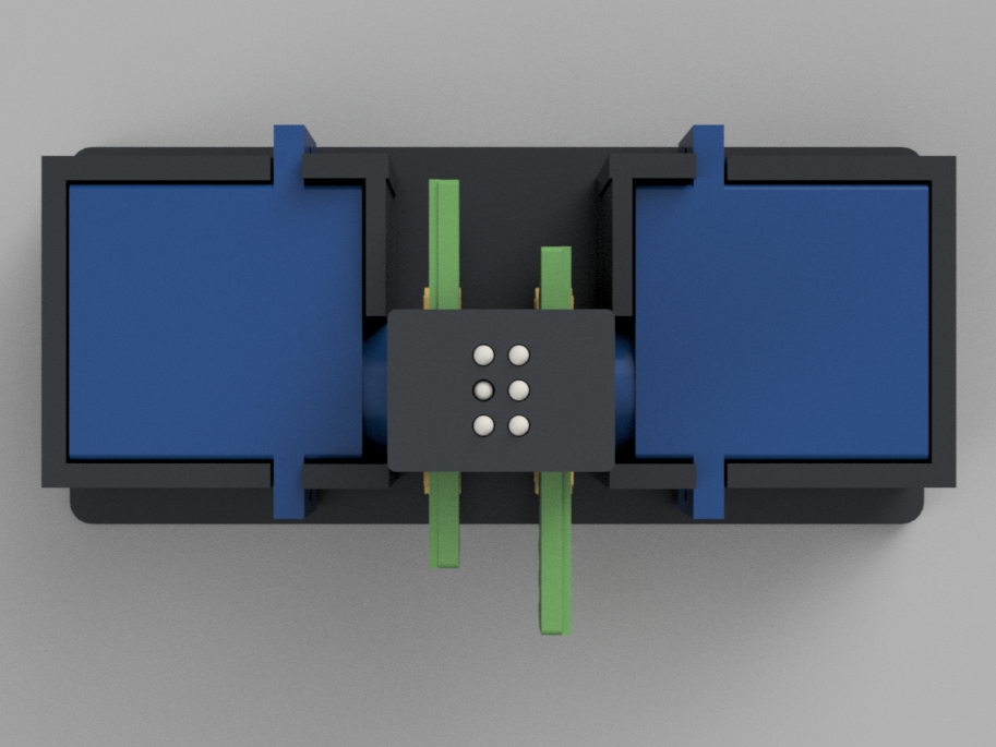
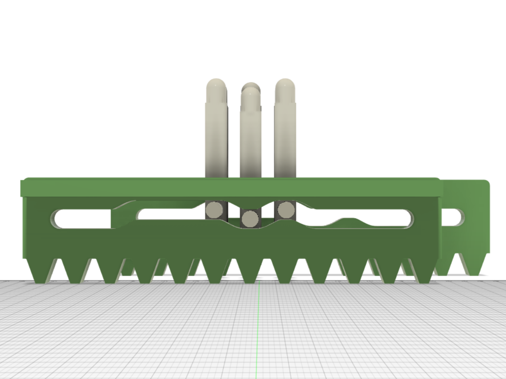
During the horizontal movement of the rack, the followers move along different heights of the profile and generate vertical movements that allow the Braille dots to be raised or retracted.
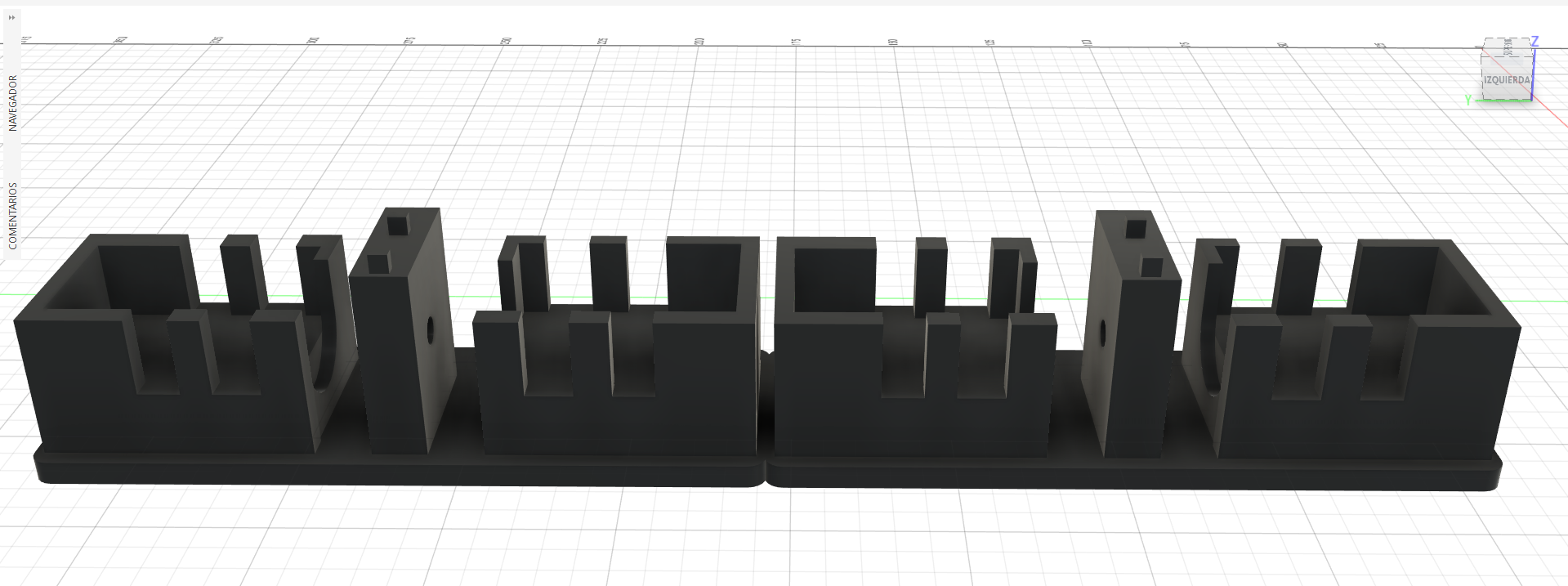
The distribution of supports and slots to maintain the alignment of the parts during operation.
And finally, the design changed a little from what was initially proposed. A different approach was taken to integrate a bidirectional system.
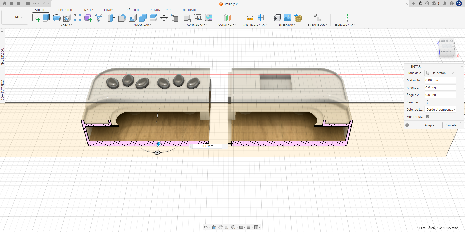
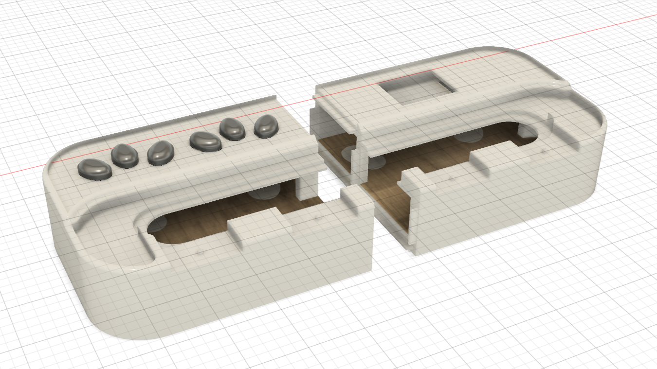
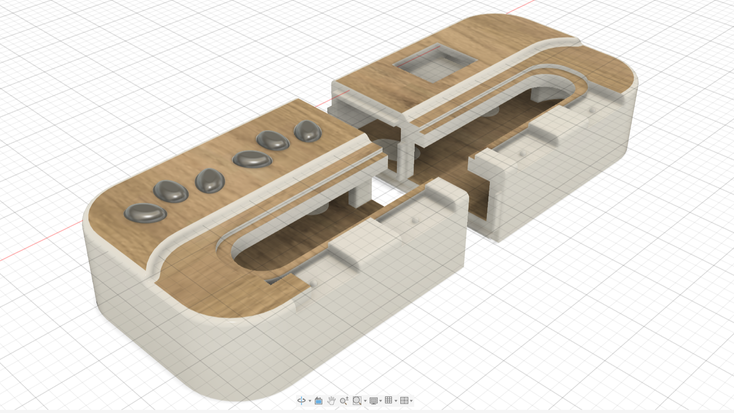
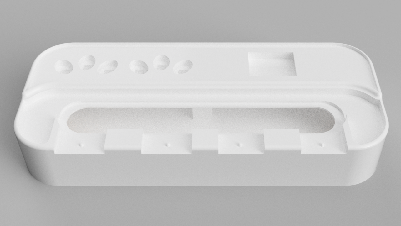
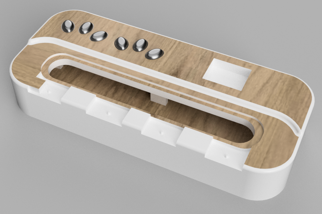
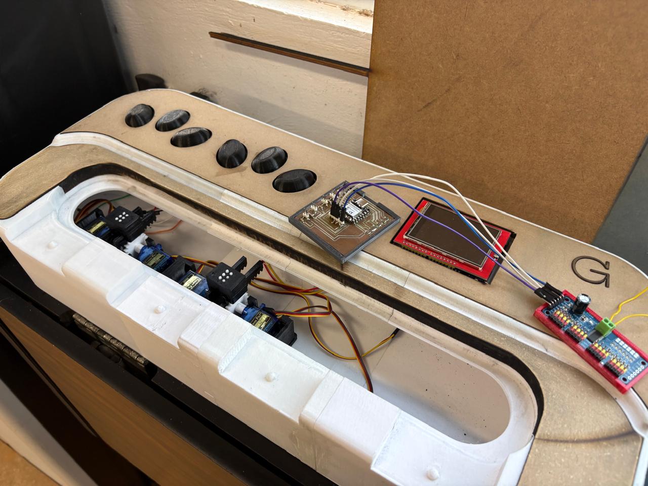
In addition, electronic integration will be less complex. Instead of developing a circuit to control several solenoids, we will use servomotors controlled by the XIAO using PWM signals. The necessary adjustments for the buttons will also be made.
Assembly Integration
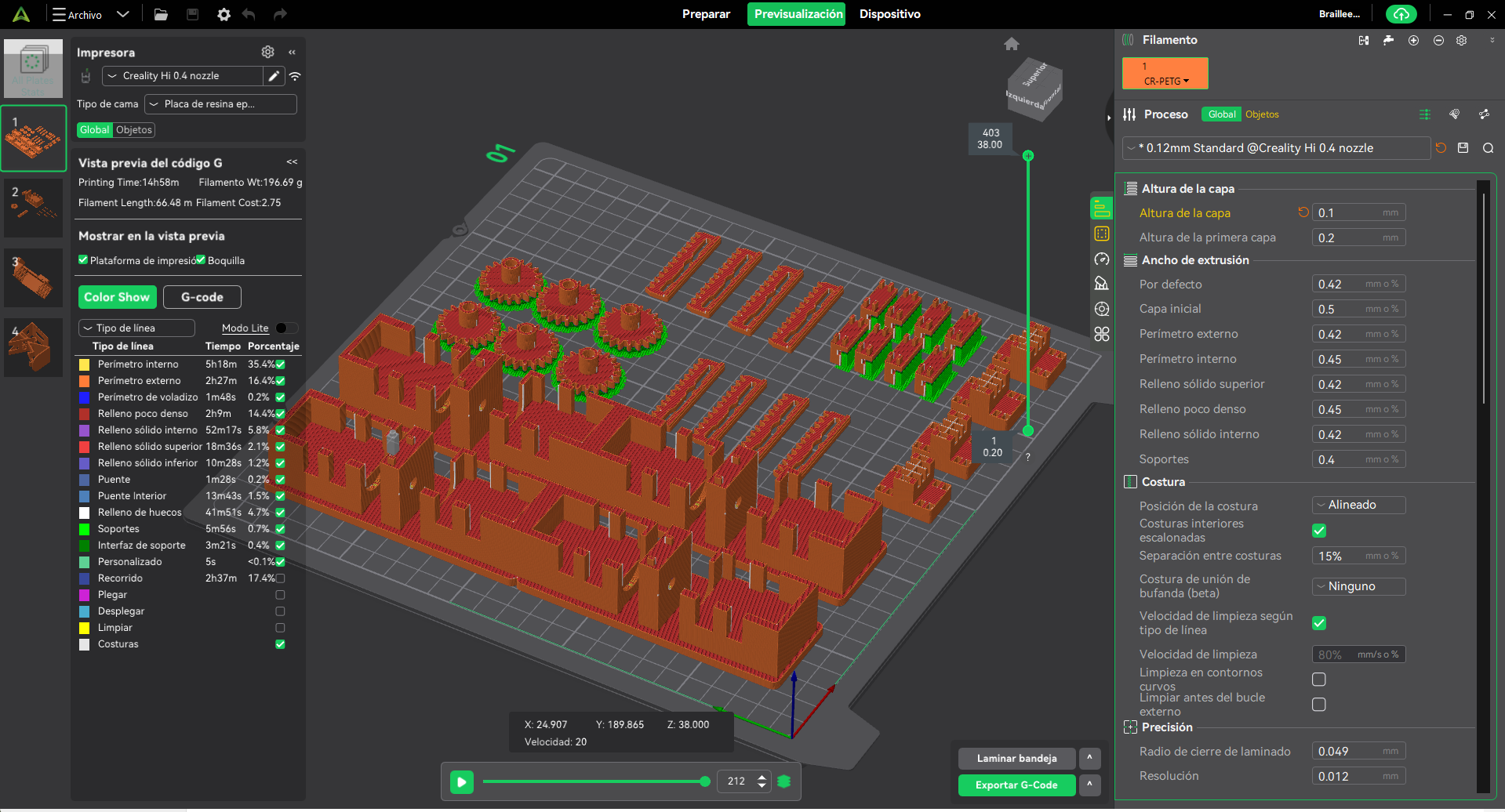
Another problem was the manufacture of the mechanical components using 3D printing, since it was not only a matter of sending the parts to be printed but also of performing an accurate calibration due to the manufacturing tolerances. We used a 0.4 mm nozzle with a layer height of 0.1 mm which represented a challenge due to the small size of the parts.
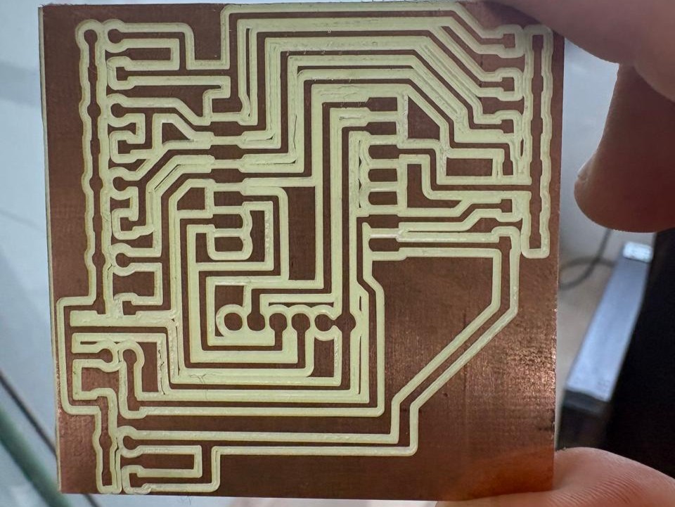
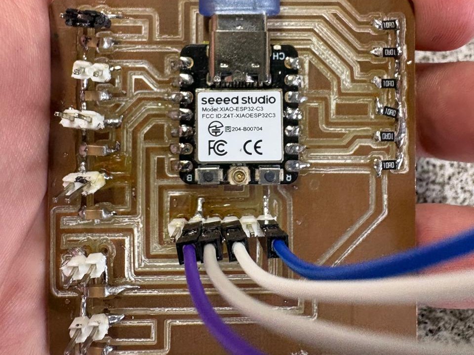
Fabrication of the PCB and assembly of the components with the XIAO ESP32C3 microcontroller.
Functional Testing
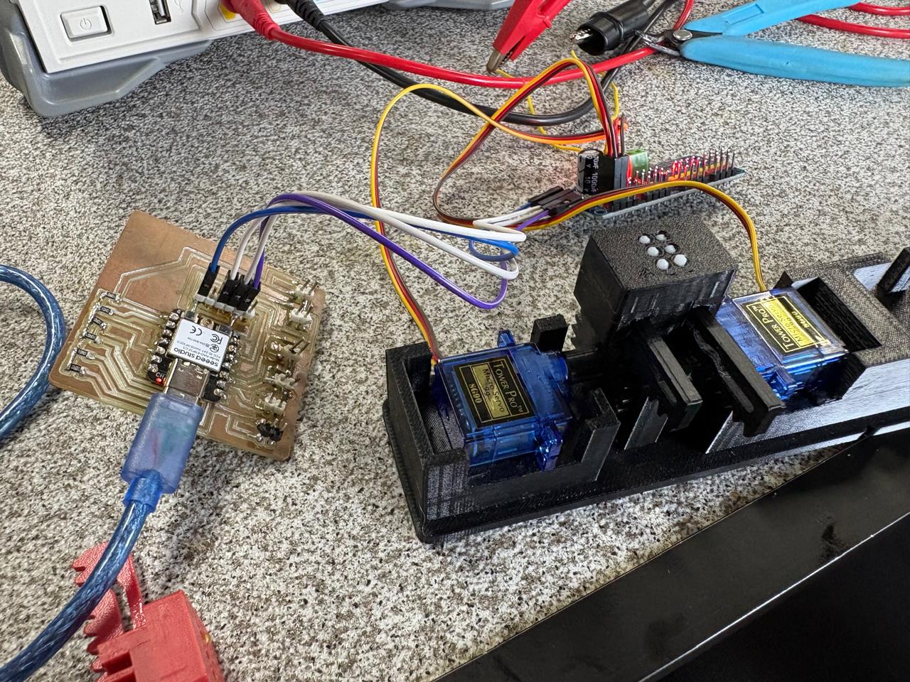
Integration of Braille Cells
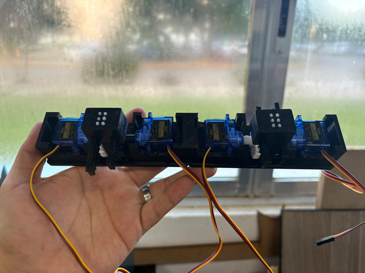
IT'S ALIVE!!!
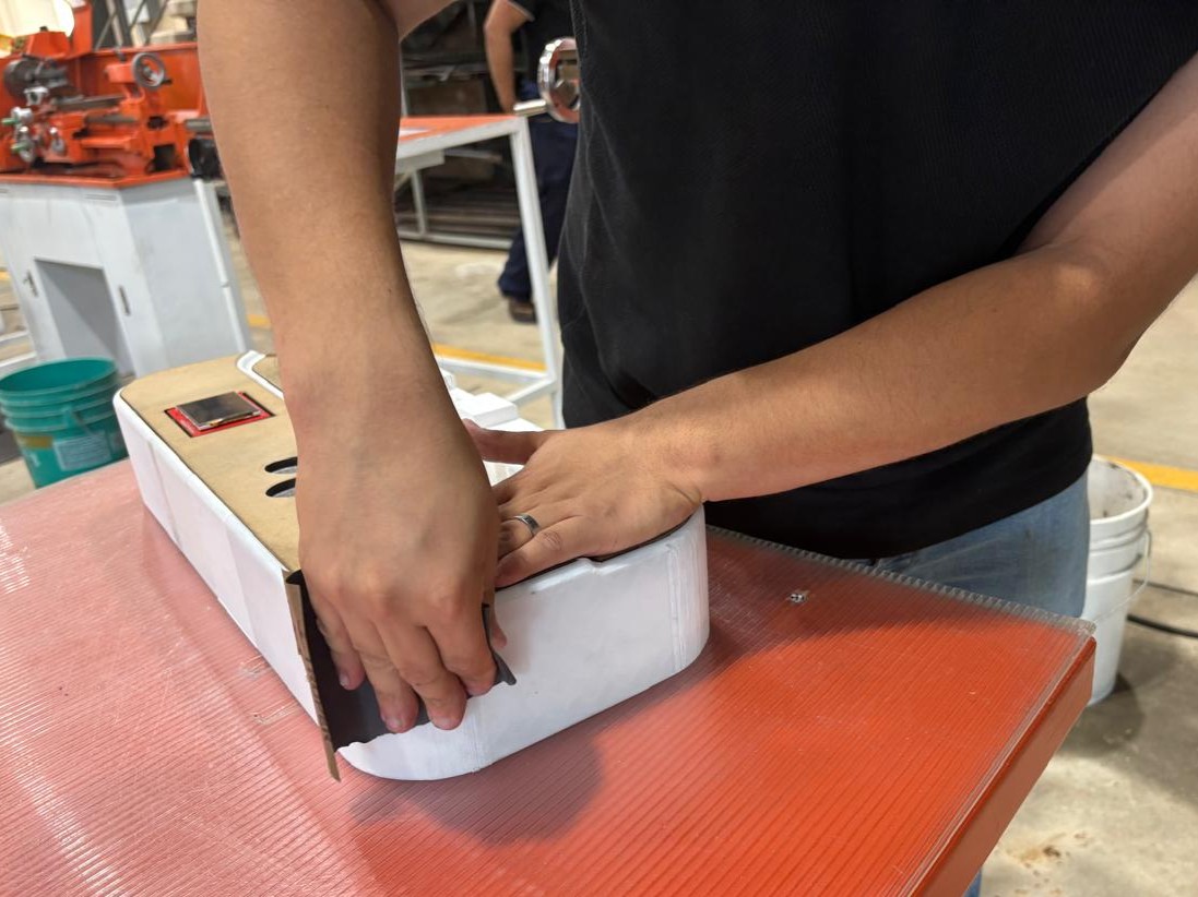
Implementation of the Design