Input Devices
Tools
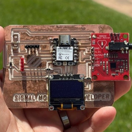
Signal Monitor Developer
Custom Board
Custom PCB Design
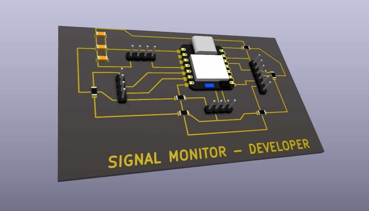
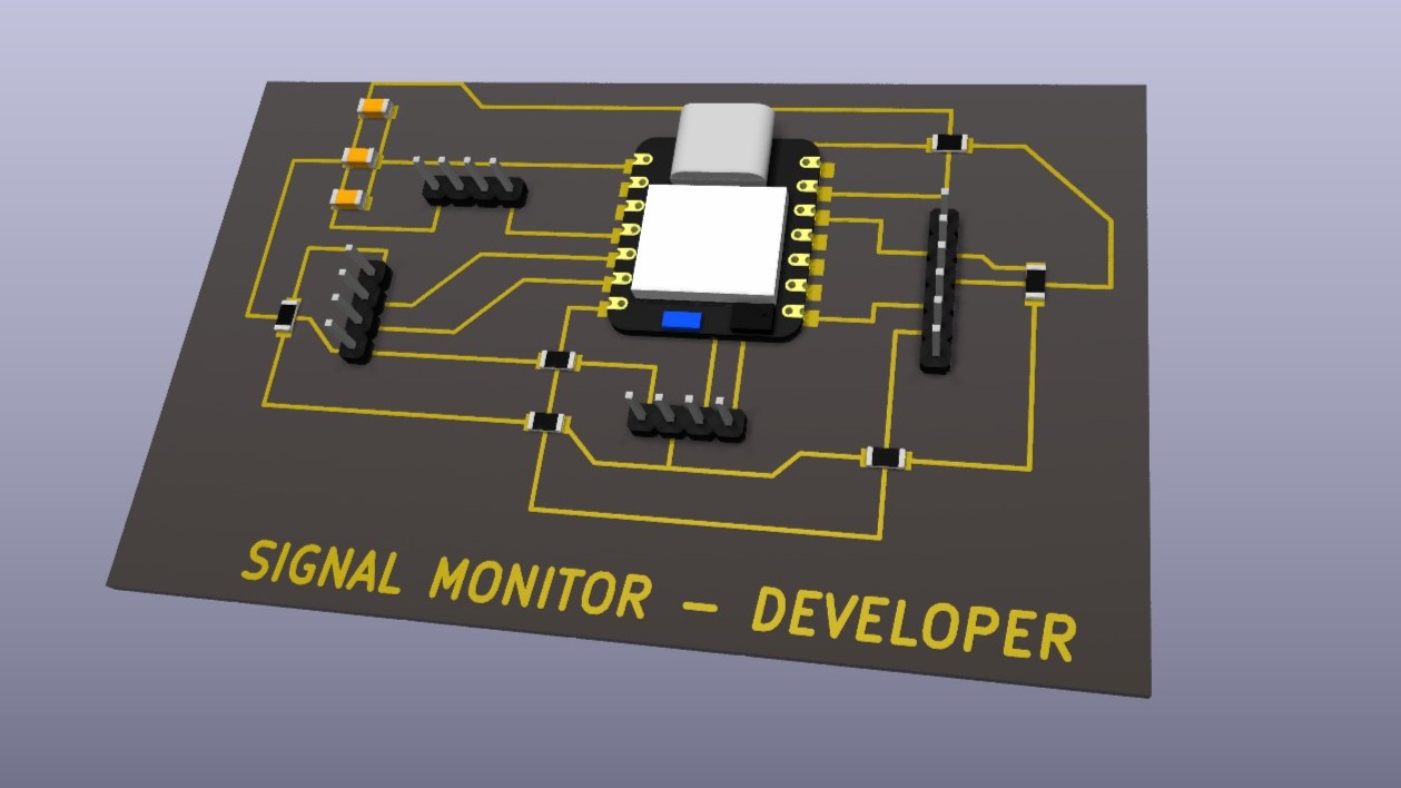
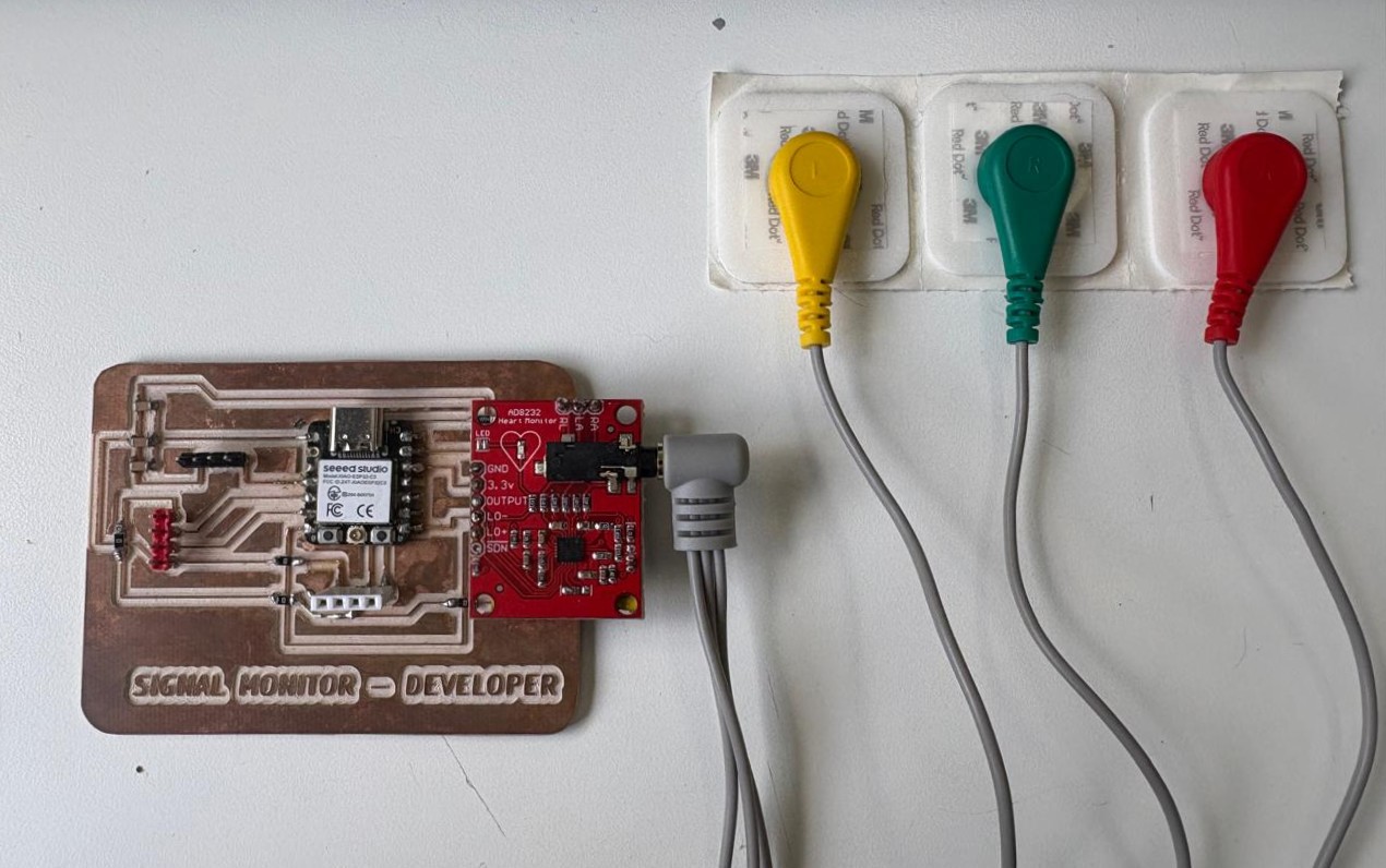
I designed a custom PCB with the objective of creating a compact board capable of receiving an input signal. In this case, the signal comes from my own body. The idea was to integrate two essential components for signal conditioning and reading: one for measuring heart rate and another one for measuring oxygen saturation, allowing future integration with other devices.
Before designing the board, it was important to understand that a biological signal, such as a signal generated by the human body, cannot be connected directly to a microcontroller. These signals usually have very low amplitude and can be affected by electrical noise, electrode movement, external interference, and baseline variations.
In my case, I used a specialized module that allows a simpler implementation of a signal conditioning stage before processing the signal with the microcontroller. The objective of this circuit is to use body signals as an input for the system, either to monitor a biological signal or to activate an electronic response based on that signal.
-
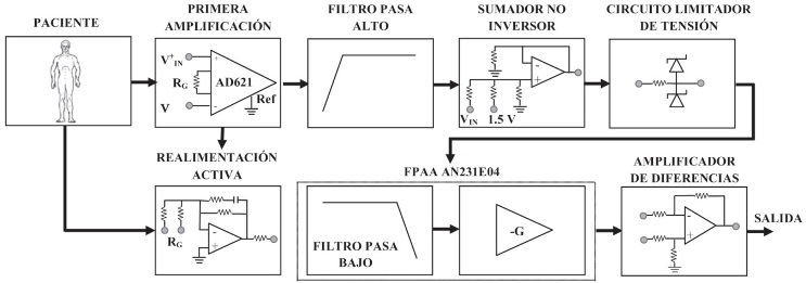
Stage 1: Signal acquisition
The signal is obtained through electrodes placed on the body. This signal has low amplitude and is highly sensitive to noise. -
Stage 2: Initial amplification
The differential signal is amplified so it can be processed by the electronic system. -
Stage 3: High-pass filtering
Slow variations, baseline drift, and noise caused by electrode movement or poor contact are reduced. -
Stage 4: Active feedback
Common-mode noise is reduced, improving the stability of the measured signal. -
Stage 5: Low-pass filtering
High-frequency interference is attenuated while preserving the useful range of the biological signal. -
Stage 6: Signal level adjustment
The signal is adapted to a voltage range compatible with the microcontroller. -
Stage 7: Input protection
The voltage is limited to prevent out-of-range values from damaging the system. -
Stage 8: Conditioned output
The final signal is amplified, filtered, and ready to be read by the microcontroller.
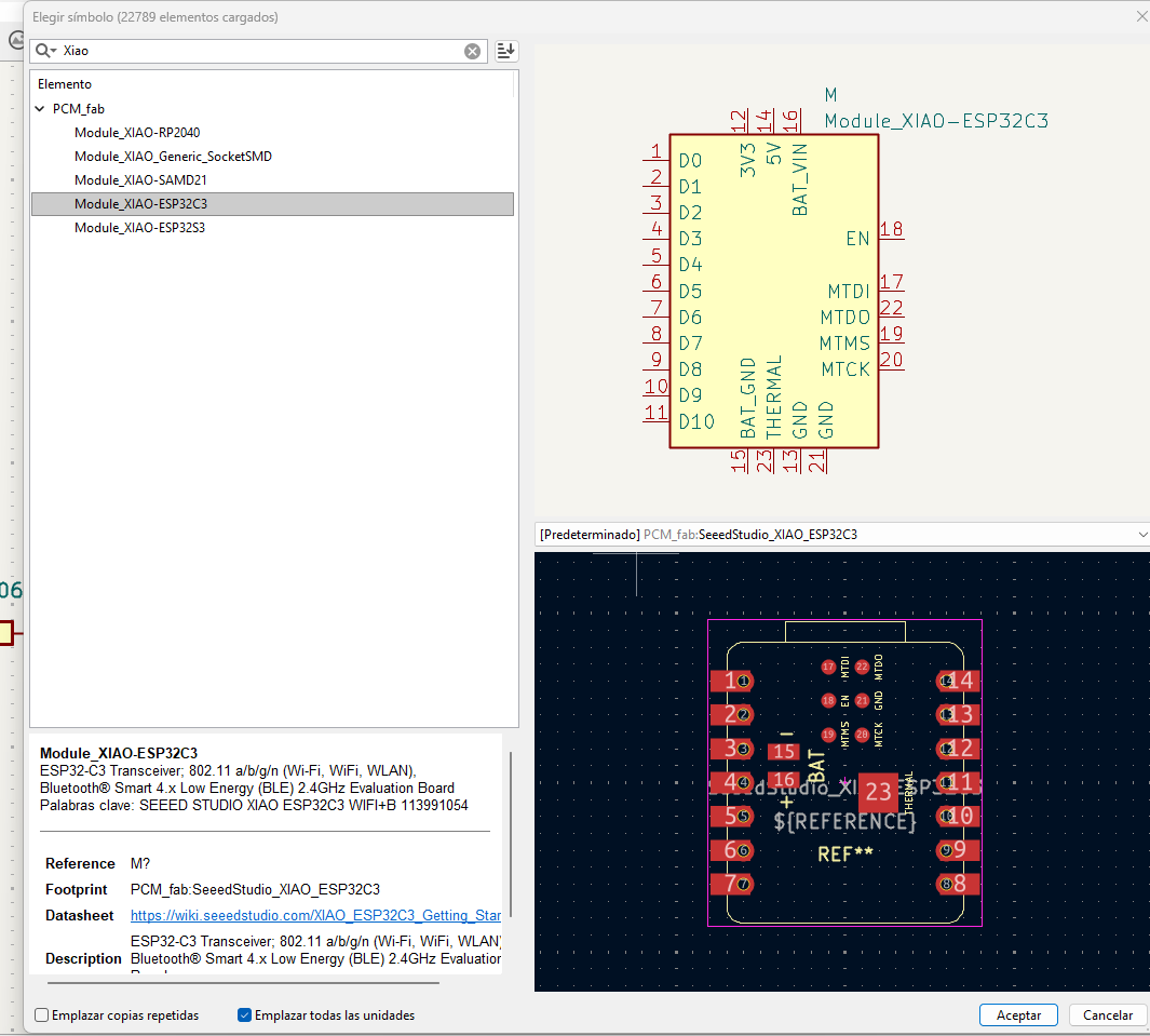
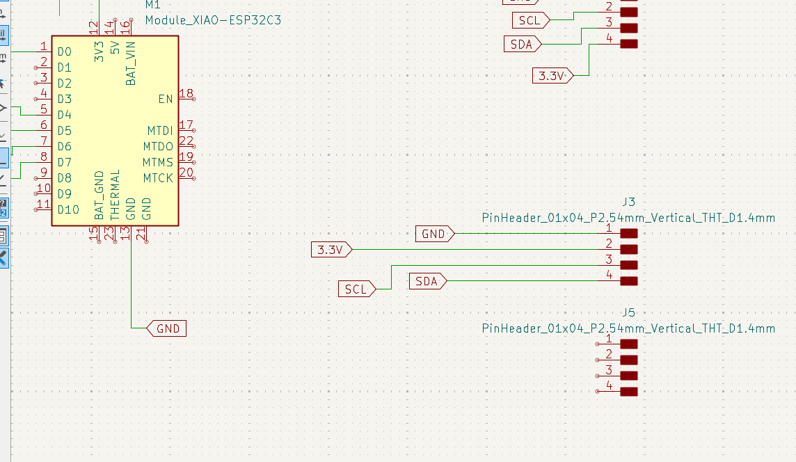
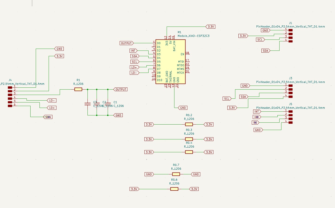
The first step was to select the correct symbol for the Seeed Studio XIAO ESP32C3 module. Then, the connections for the input signal, output, I2C communication, power, and ground were assigned.
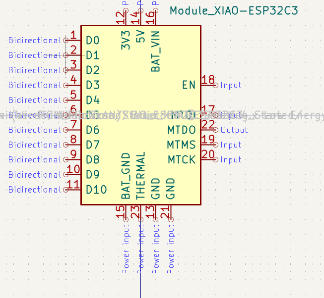
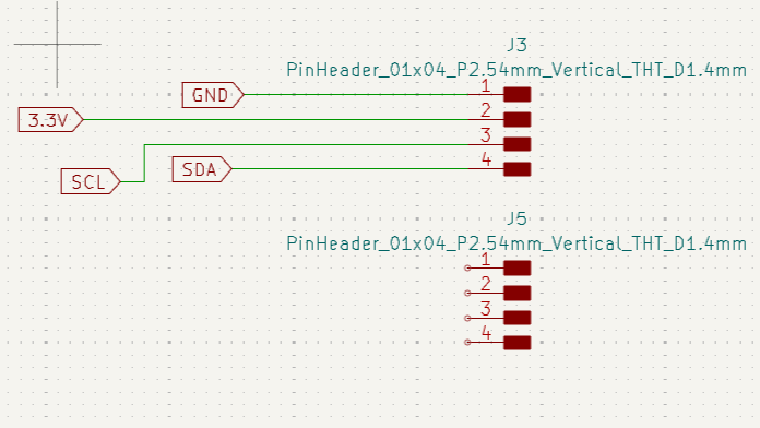
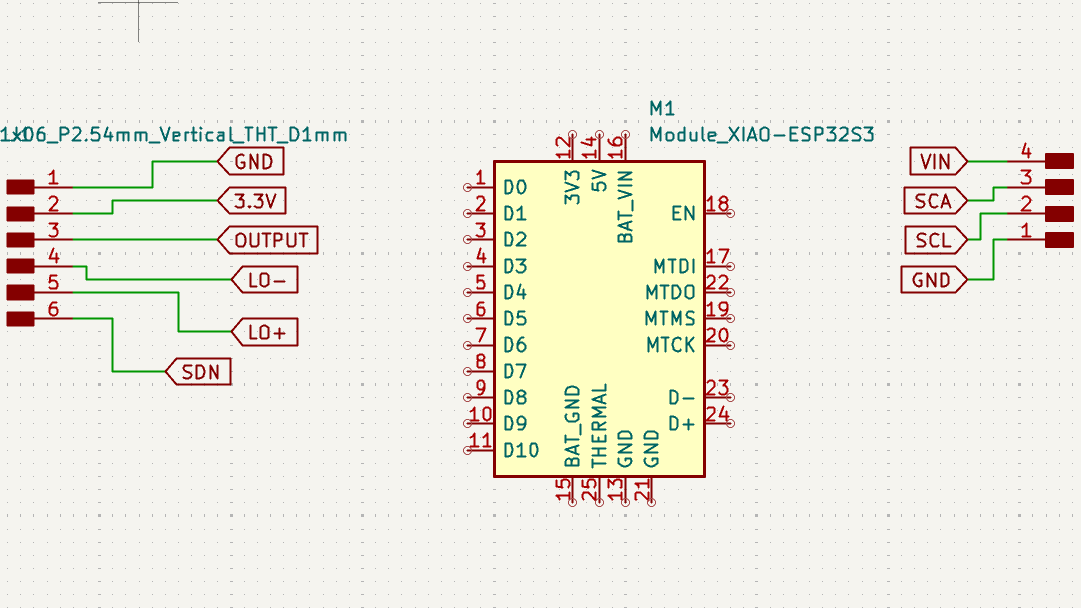
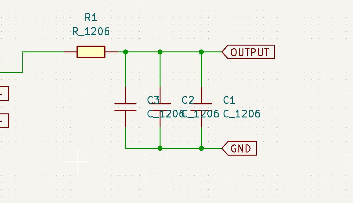
A basic signal conditioning stage was also integrated, composed of a resistor and capacitors connected to ground. The purpose of this section is to help stabilize the signal and reduce possible noise before it is processed by the microcontroller.
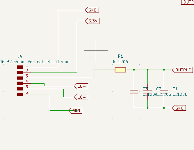
The complete schematic was reviewed to verify that the microcontroller, connectors, power lines, inputs, outputs, and passive components were correctly connected before moving on to the physical PCB design.
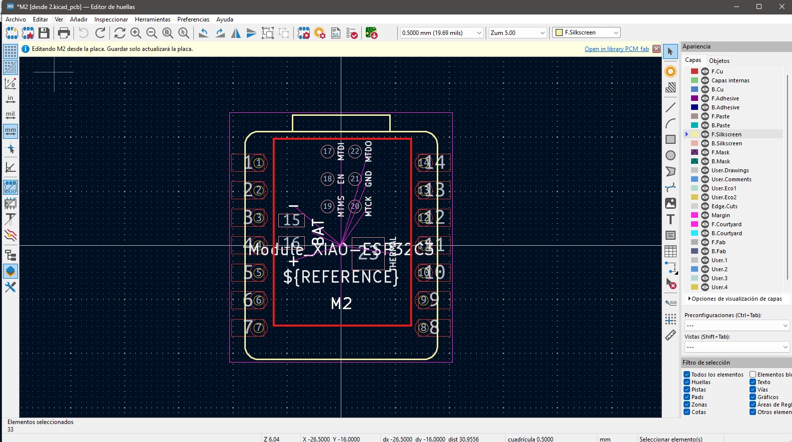
For the PCB design, the footprint of the XIAO ESP32C3 module was modified, since some connections were not necessary for the purpose of this board.
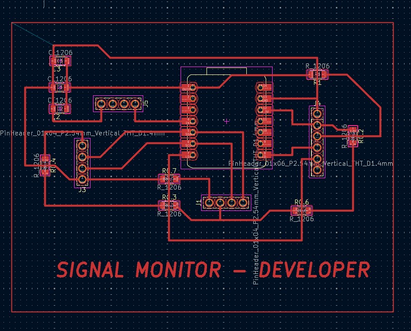
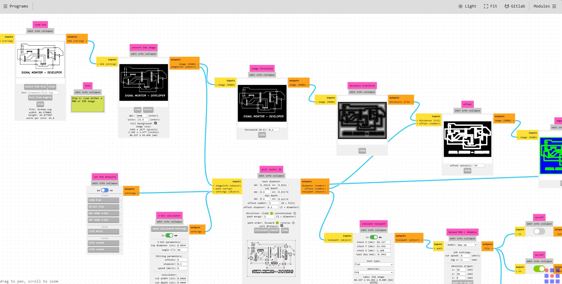
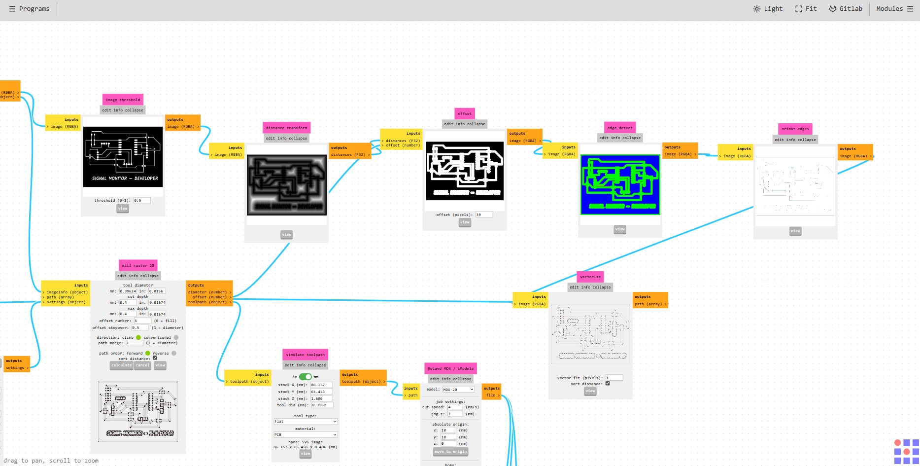
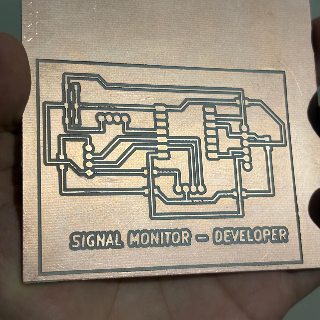
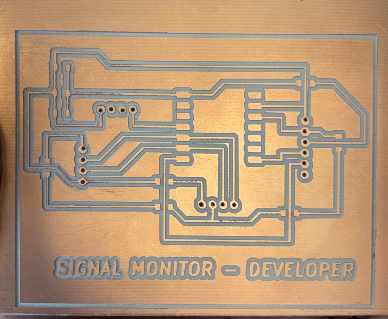
Board Fabrication
With the schematic completed, I proceeded to design the PCB and generate the fabrication files using MODS.
PERFECT
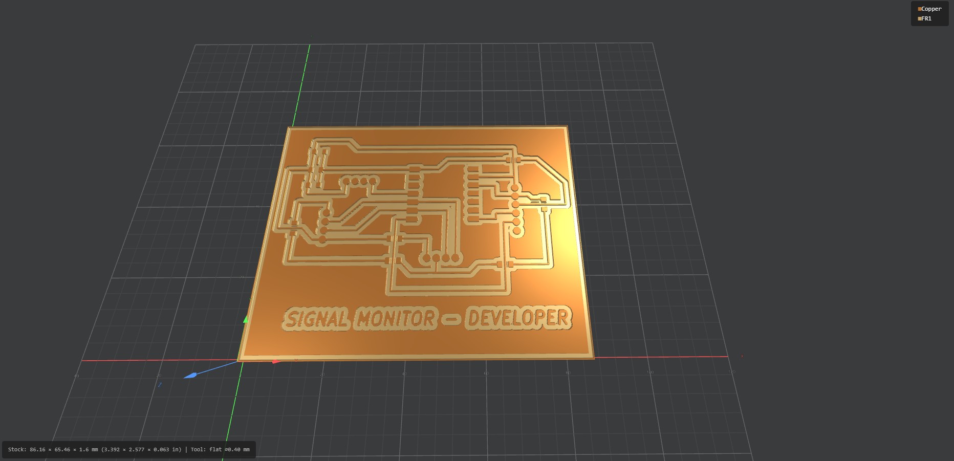
Let's get down to work
My Baby...
Signal conditioning
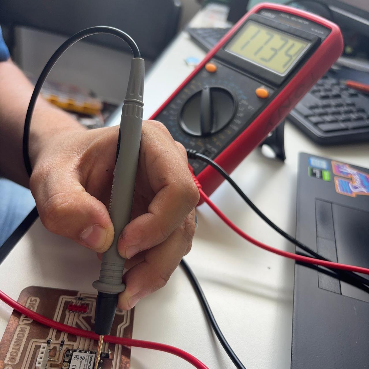
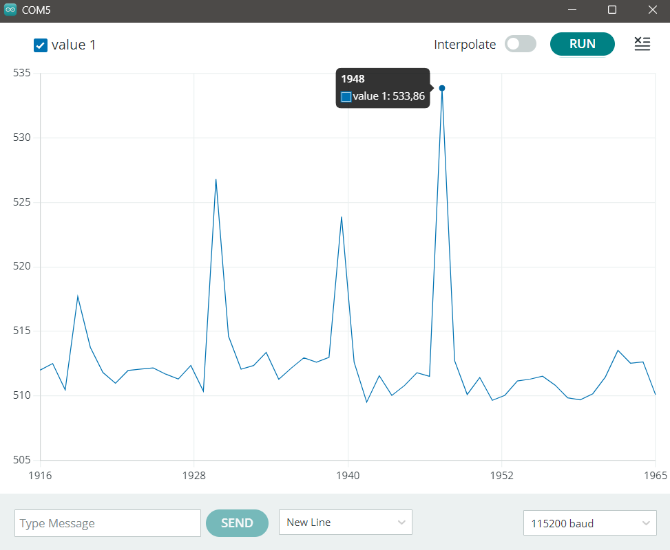
To obtain a reliable reading, two main adjustments were necessary: signal conditioning and OLED data visualization.
First, the raw sensor signal had to be cleaned and stabilized. Since the signal contained noise and fluctuations, electronic components and software filters were used to improve the quality of the measurement.
#include <Arduino.h>
#define USE_XIAO_ESP32C3 true
#if USE_XIAO_ESP32C3
const int ecgInputPin = 2; // D0 on XIAO ESP32-C3
#else
const int ecgInputPin = 34; // Analog input on standard ESP32
#endif
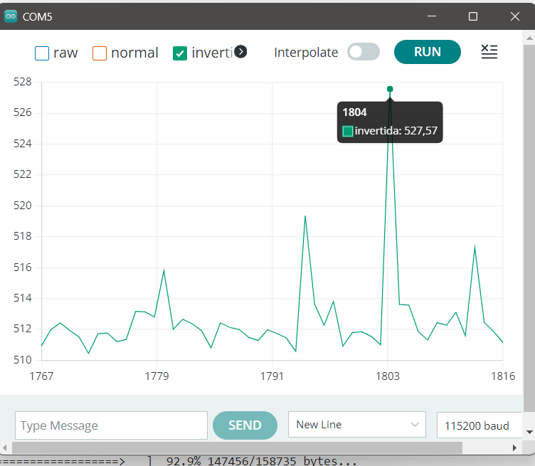
const bool invertEcgWaveform = true;
const float displaySignalGain = 1.8;
const unsigned long samplingIntervalUs = 4000; // 250 Hz sampling rate
unsigned long lastSampleTimeUs = 0;
const int adcAverageSamples = 4;
const float baselineFilterAlpha = 0.997;
const float ecgSmoothingAlpha = 0.70;
float baselineValue = 0;
float filteredEcgSignal = 0;
float heartRateThreshold = 620.0;
const unsigned long beatRefractoryPeriodMs = 350;
const unsigned long heartRateTimeoutMs = 3000;
float averagedBpm = 0;
unsigned long lastBeatTimeMs = 0;
bool signalAboveThreshold = false;
unsigned long lastSerialPrintTimeMs = 0;
float readAveragedAdc() {
long adcSum = 0;
for (int sampleIndex = 0; sampleIndex < adcAverageSamples; sampleIndex++) {
adcSum += analogRead(ecgInputPin);
}
// Converts 12-bit ADC range from 0-4095 to 0-1023
return (adcSum / (float)adcAverageSamples) / 4.0f;
}
void resetHeartRateCalculation() {
averagedBpm = 0;
lastBeatTimeMs = 0;
signalAboveThreshold = false;
}
void updateHeartRate(float displayedSignal) {
unsigned long currentTimeMs = millis();
if (lastBeatTimeMs != 0 && (currentTimeMs - lastBeatTimeMs > heartRateTimeoutMs)) {
resetHeartRateCalculation();
}
if (!signalAboveThreshold &&
displayedSignal > heartRateThreshold &&
(currentTimeMs - lastBeatTimeMs > beatRefractoryPeriodMs)) {
signalAboveThreshold = true;
if (lastBeatTimeMs != 0) {
unsigned long beatIntervalMs = currentTimeMs - lastBeatTimeMs;
float instantBpm = 60000.0f / beatIntervalMs;
if (instantBpm >= 40 && instantBpm <= 180) {
if (averagedBpm == 0) {
averagedBpm = instantBpm;
} else {
averagedBpm = (0.75f * averagedBpm) + (0.25f * instantBpm);
}
}
}
lastBeatTimeMs = currentTimeMs;
}
if (displayedSignal < (heartRateThreshold - 45.0f)) {
signalAboveThreshold = false;
}
}Extra
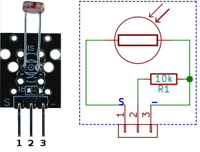
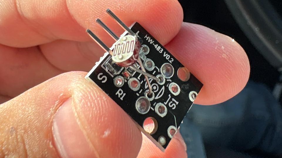
Photoresistor module
It’s a voltage divider configuration formed by the LDR and a 10 kΩ resistor. The system converts light intensity into variations in voltage. The output signal is taken from the midpoint and connected to the signal pin.
Microphonee
The microphone, biased with a 10 kΩ resistor, converts sound into a low-amplitude analog signal that is filtered and conditioned. This signal is then compared against a reference voltage adjustable through a 10 kΩ potentiometer, generating an analog output (AO) proportional to the sound level (0–VCC, 3.3–5 V) and a digital open-collector output (DO) that is triggered when the threshold is exceeded, including pull-up resistors and a two-state indicator LED.
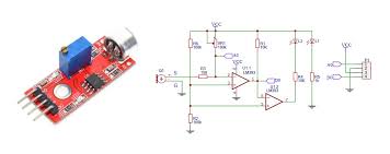
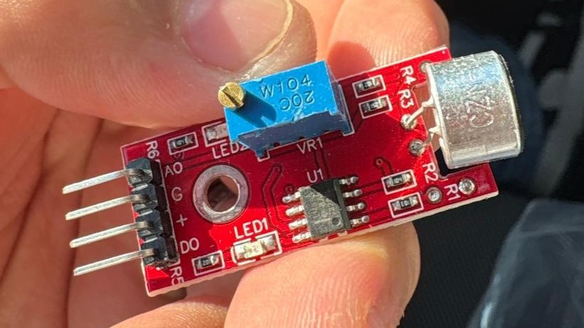
The KY-038 sound sensor module uses an electret microphone to detect sound variations. The module also integrates an operational amplifier and a potentiometer used to adjust the sensitivity of the signal output.