Networking and communication
Tools


Node to Node
Xiao vs Xiao
The XIAO ESP32 supports Wi-Fi and Bluetooth Low Energy (BLE), allowing wireless communication between devices through an external antenna. It can also be used with other wireless protocols, such as LoRa, by adding an external radio module.
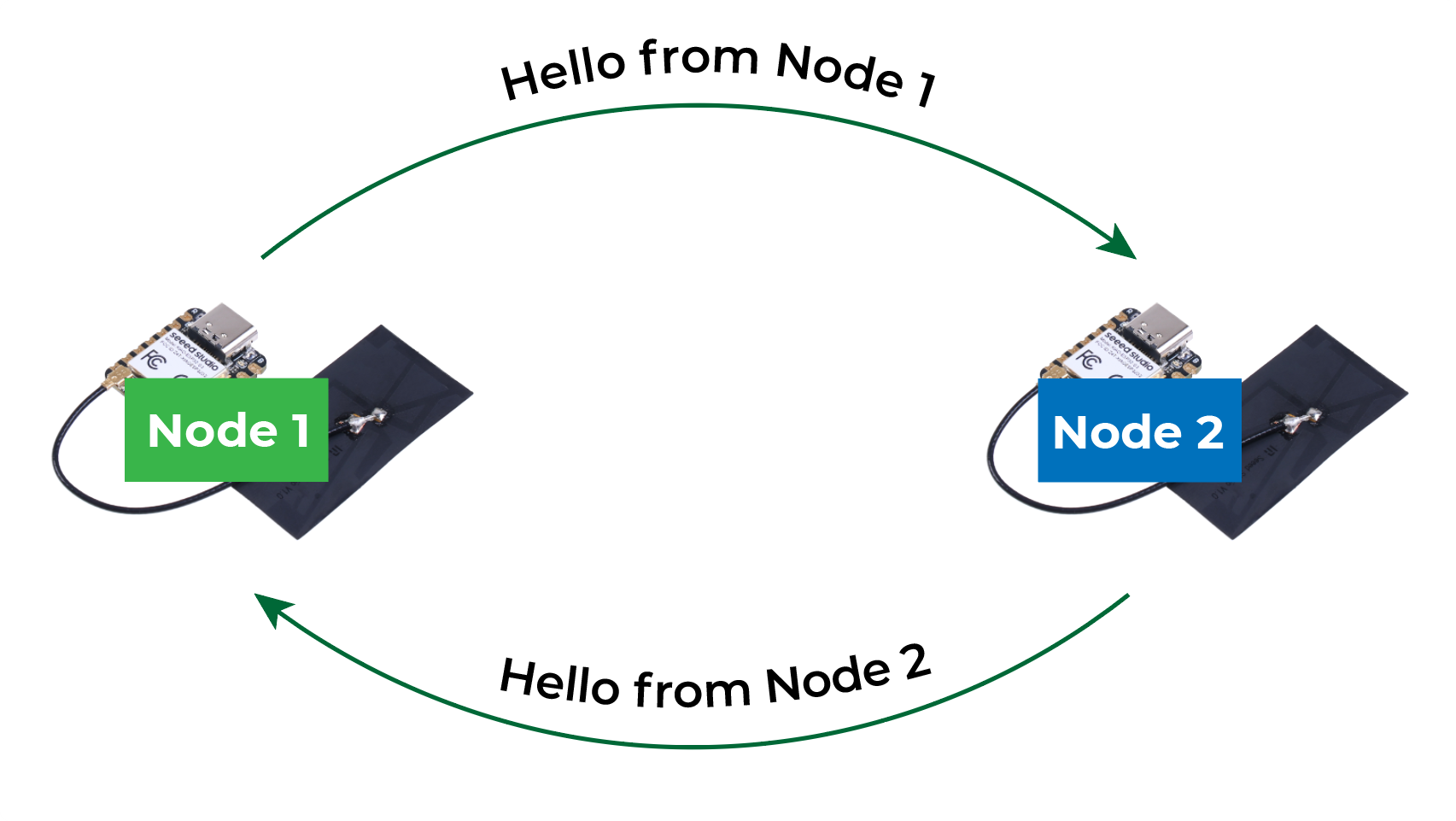
Before starting the tests, the PCB traces were designed, since its implementation is part of later stages of the project focused on bidirectional communication.
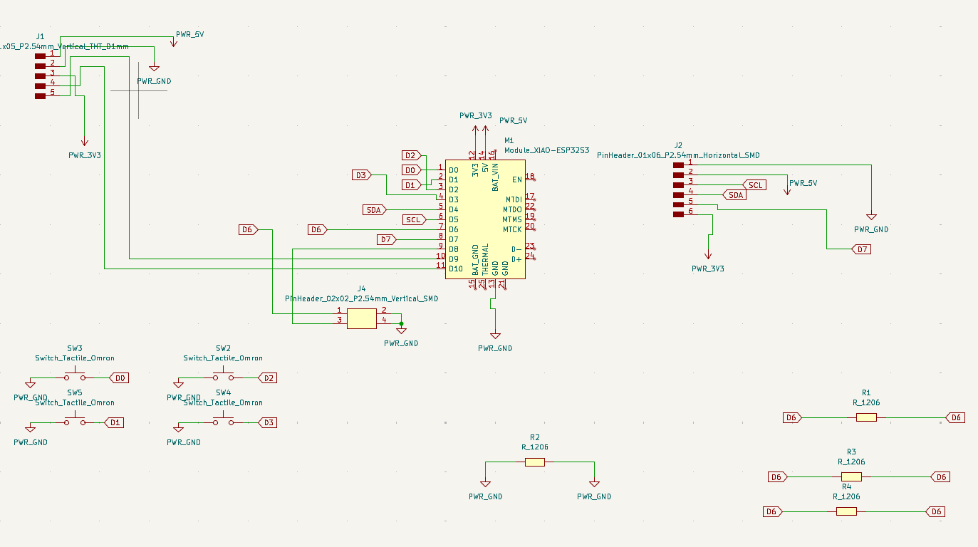
In one of the designs, we decided to implement a board that resembled the basic operation of our Braille system and that also considered the communication protocols necessary to connect the devices. Another design that we will use is a board previously made in one of the assignments to check the communication between nodes.
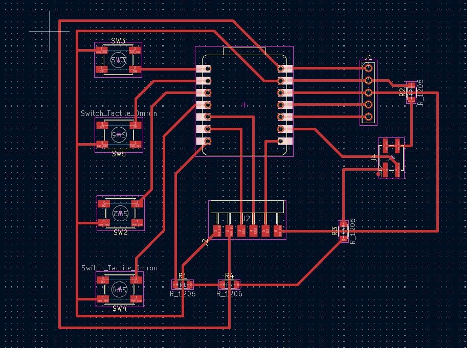
At this stage, we included the developed board in our PCB inventory as part of the project prototyping stage. This allowed us to better understand the project limits and the necessary adjustments for the next stages.
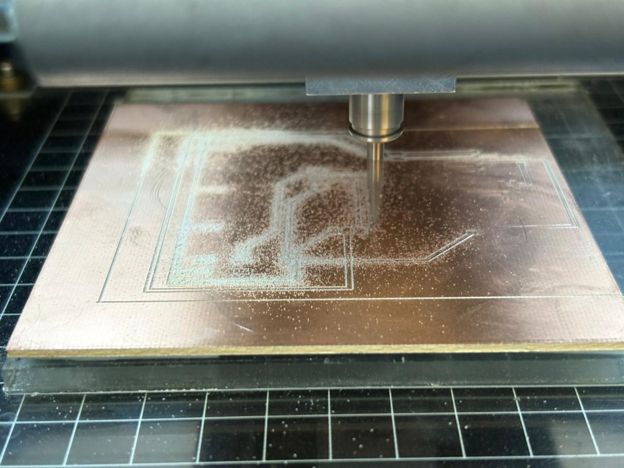
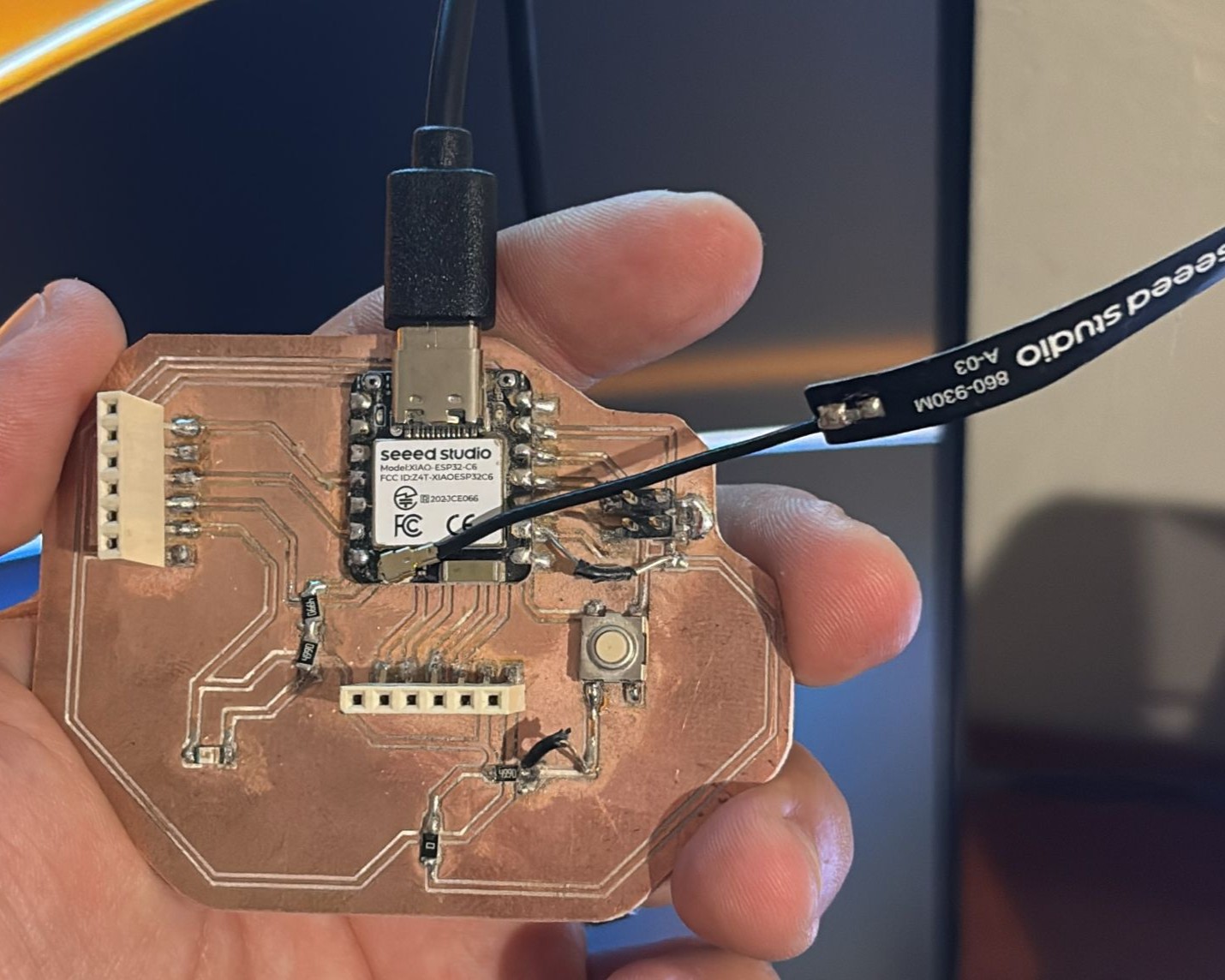
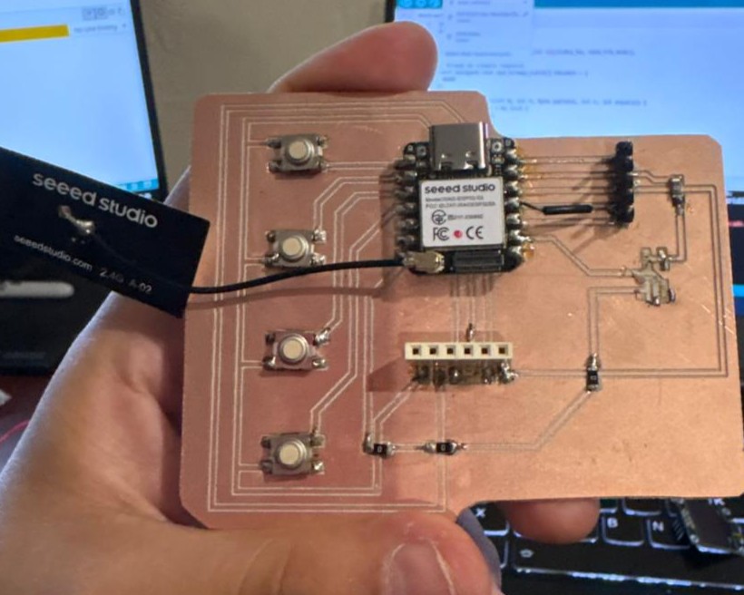
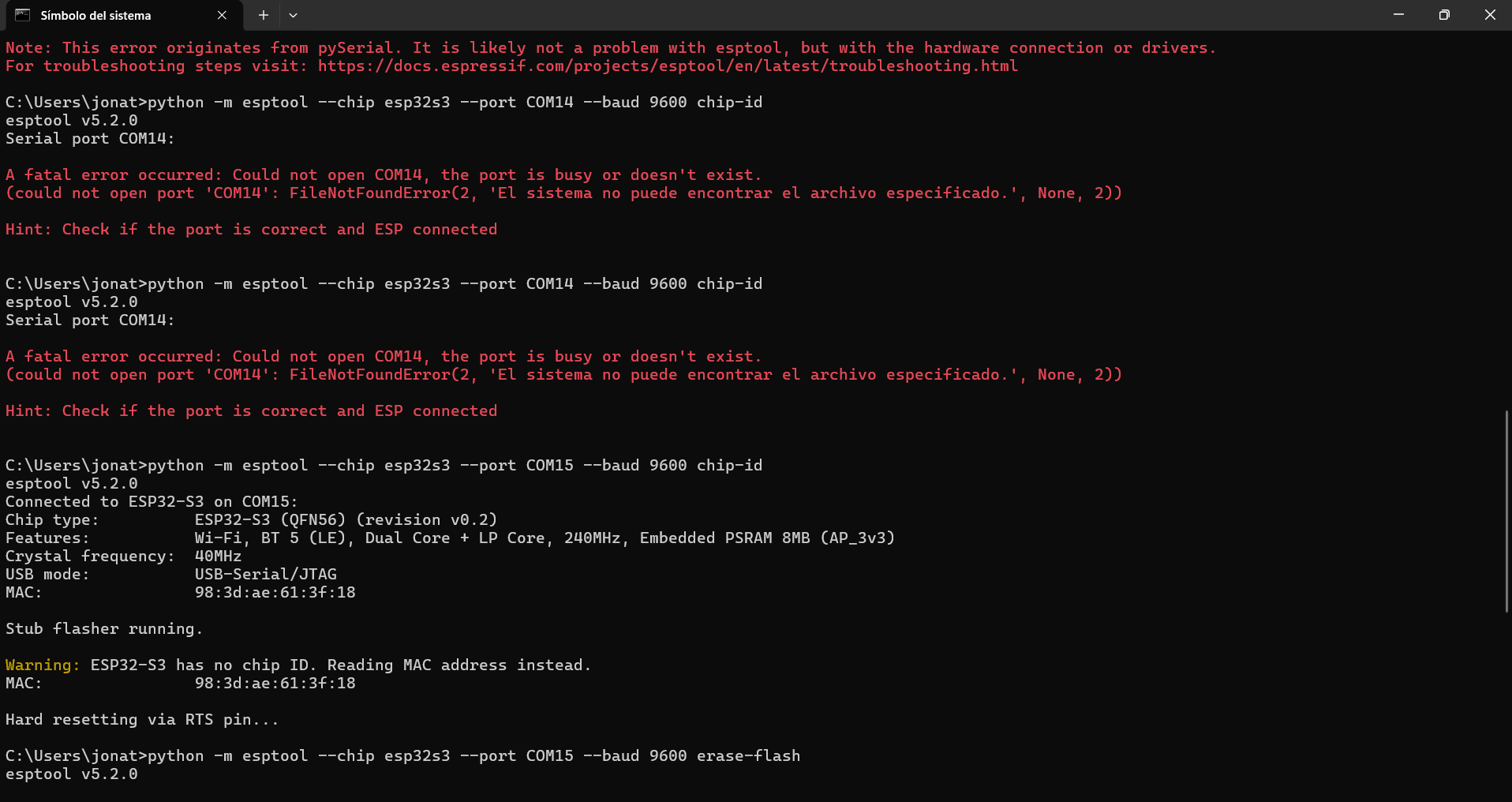
During programming we had connection problems with the XIAO ESP32-S3 because the system could not recognize the serial port correctly. At first we tried to connect using COM14 but the system showed errors and said the port was busy or did not exist.
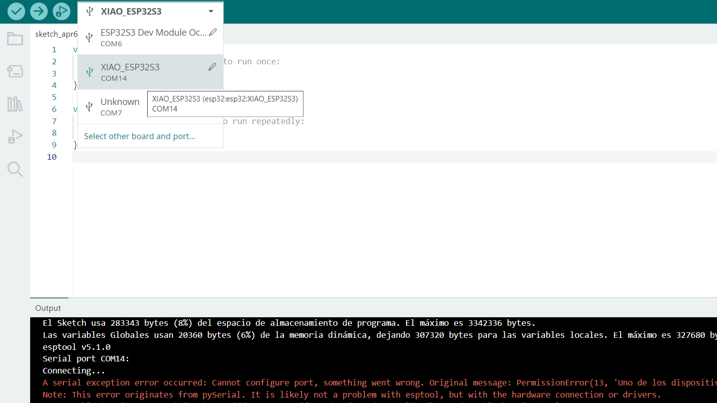
After several tests we found that the microcontroller was detected on a different port which was COM15. When we changed the port manually in the command and in the development environment the connection worked correctly.
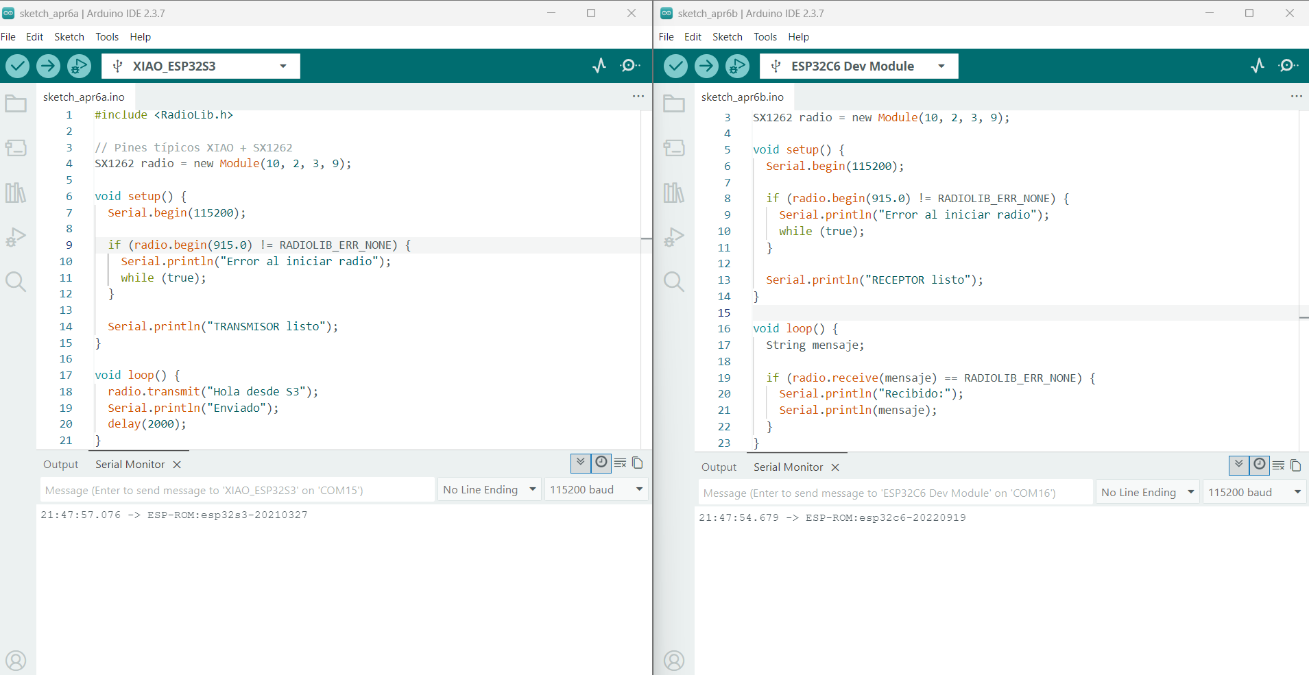
Wireless communication tests were carried out between two microcontrollers using the XIAO ESP32-S3 as transmitter and the ESP32-C6 as receiver using basic WiFi communication. The ESP32-S3 created a network and the ESP32-C6 tried to connect to it but connection problems occurred because the receiver could not establish communication correctly.
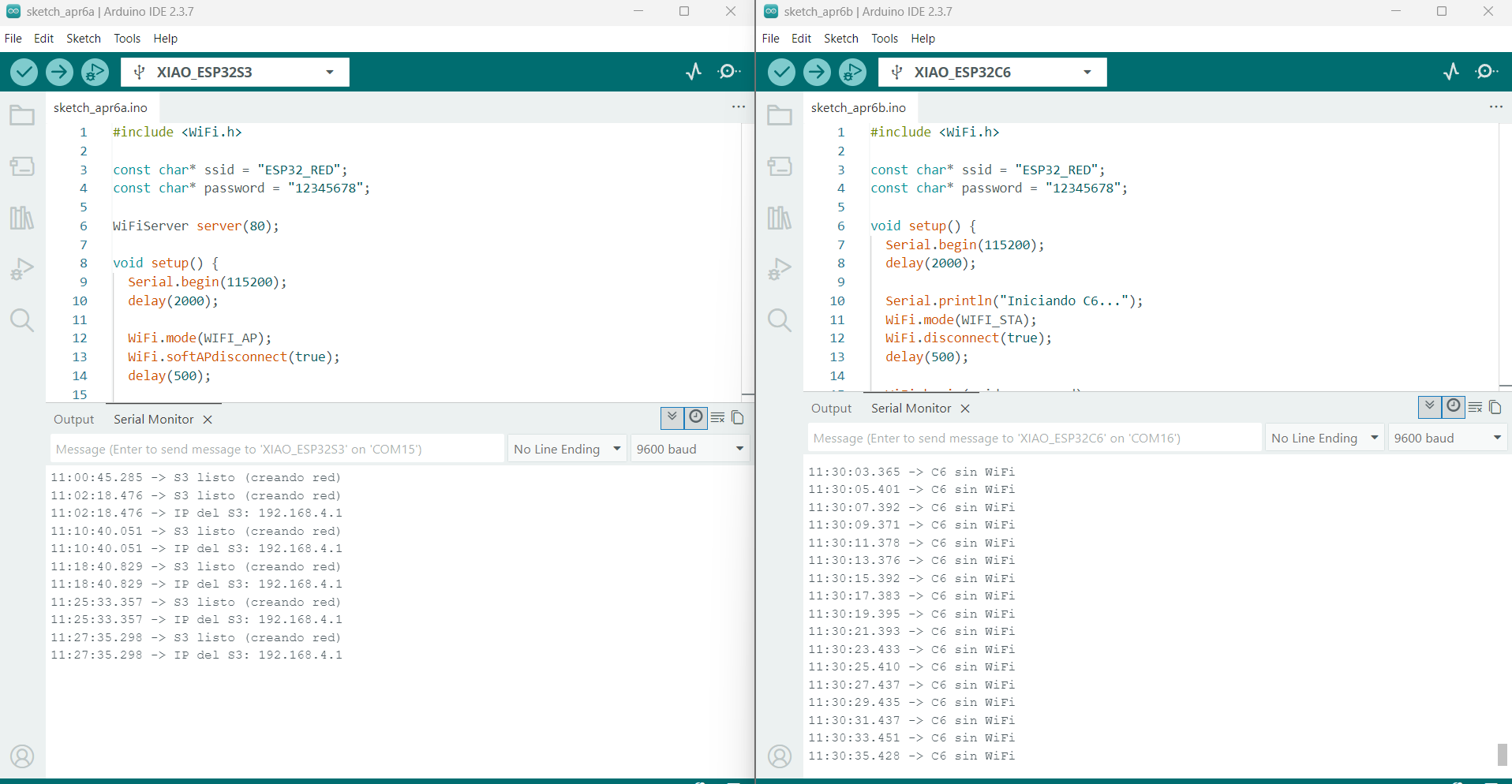
During the tests problems related to the antenna were identified since the communication behavior changed depending on its connection. To achieve correct operation between both nodes it was necessary to use the antenna connection and after this the system started working properly.
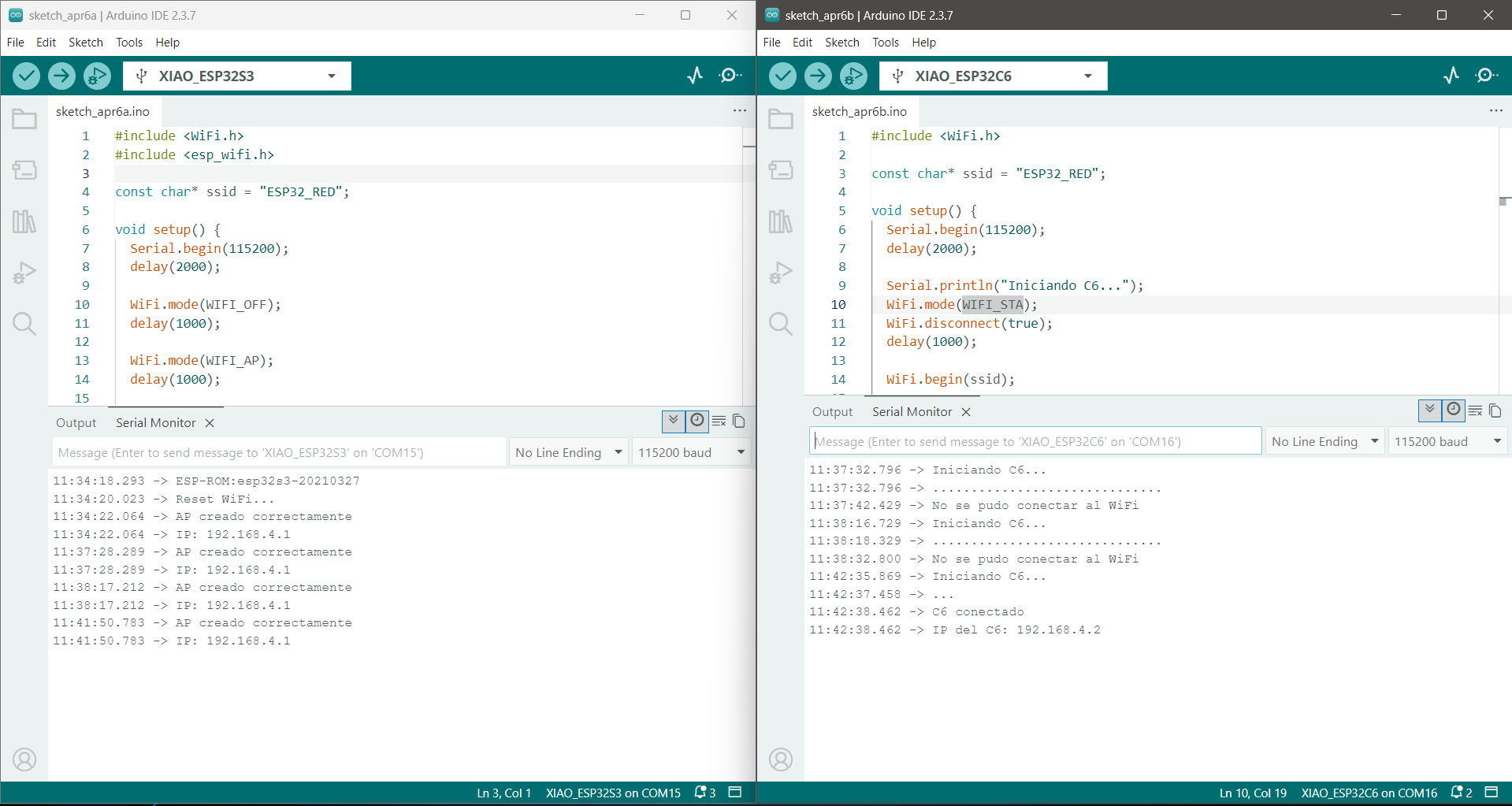
After several attempts the connection between both devices was established allowing the correct assignment of an IP address.
By establishing communication between both nodes, the project is based on a wireless communication system between two microcontrollers. The main idea is that the devices can send text messages to each other in real time, working as a simple communication channel.
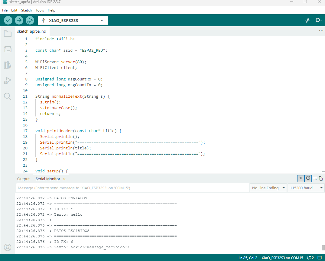
When one of the devices sends a message, the other receives it and displays it on the serial monitor. This is where the project becomes relevant: the original text is automatically converted character by character into its Braille representation.
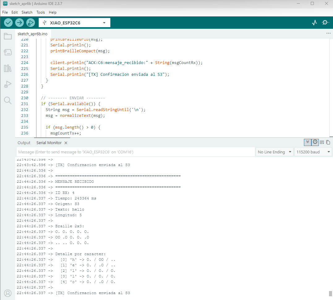
Currently the Braille output is simulated using the Serial Monitor which helps us test how the translation process works. The next step of the project is to replace this digital output with a physical Braille system to generate tactile dots.
Arduino vs Xiao
Another project we used to test the communication protocols was the connection between an Arduino UNO R4 WiFi which incorporates an ESP32-S3-MINI-1-N8 module for wireless connectivity and a XIAO ESP32-C6 previously developed during the Input Devices assignment.
This test allowed us to check the scope of the ideas we had for the project since we wanted not only to send data but also to generate interaction between the nodes through an interface.
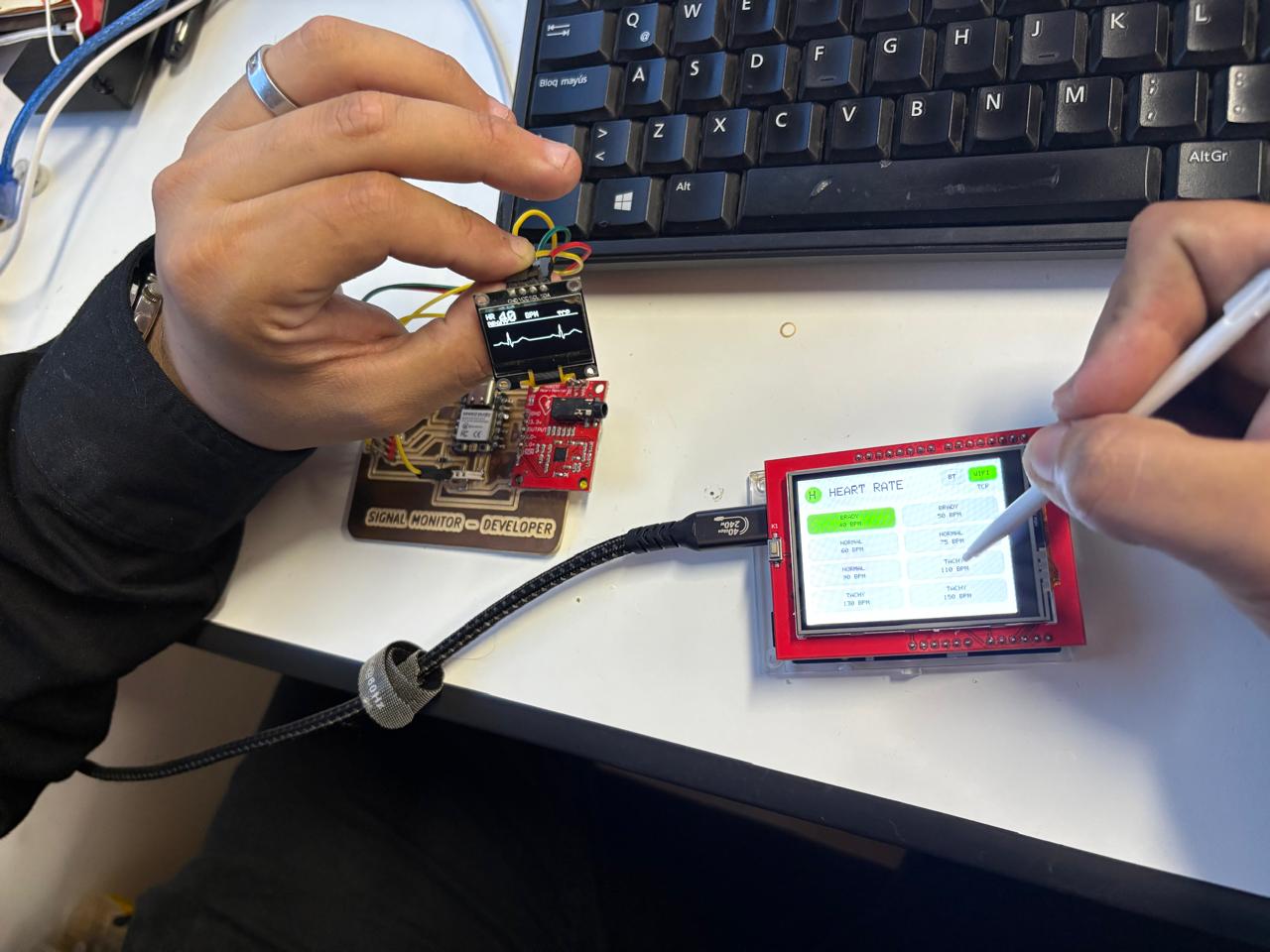
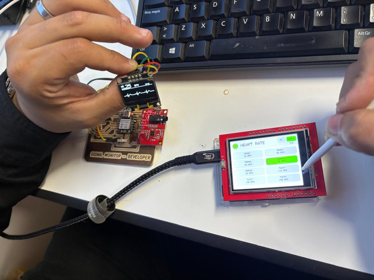
In this case the Arduino R4 works as the control node and the interface has different heart rate options. When an option is selected the information is sent to the second node. The receiving board reads the selected heart rate and updates the OLED display to show a simulation of that signal.
For example if we select a BRADY frequency on the touch screen the OLED should show a slower signal according to the selected value. In the same way if we select a NORMAL or TACHY frequency the simulation changes to visually represent that type of frequency.
The module we are using for these tests is a TFT touch screen with an interface that we developed to perform different tests for the final project and verify the operation of different parts of the Braille system.
Bluetooth
Another test we used to check the communication protocols was through Bluetooth (LightBlue App). The intention was to test the data transmission using an interface designed to convert Braille words into plain text.
During the Bluetooth communication test we also checked how the transmitted information can be displayed in different data formats. In Bluetooth Low Energy the information is transmitted as bytes and the application allows the same data to be interpreted as UTF-8 text binary hexadecimal or octal values.
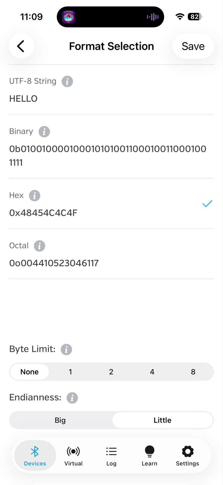
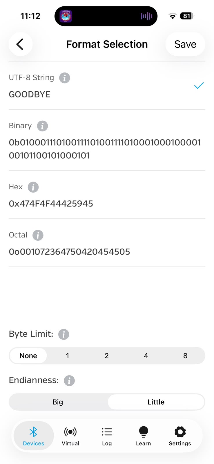
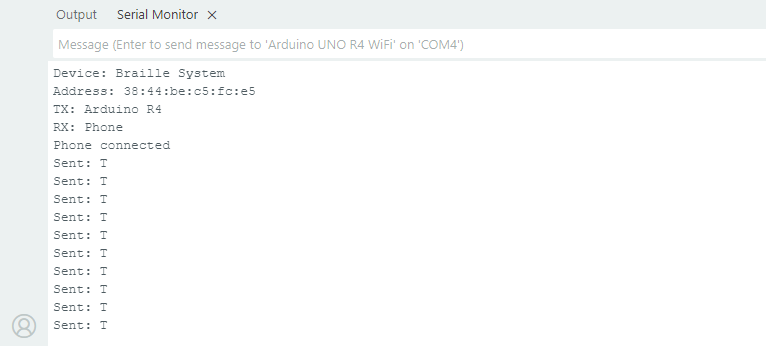
Sending information from TX: Arduino / RX: Phone simulates a future implementation in which the data generated by the first node (TX) can be received by a second node and represented in Braille through the interaction of the dynamic cells with the system. In this case the phone acts as the second node (RX).
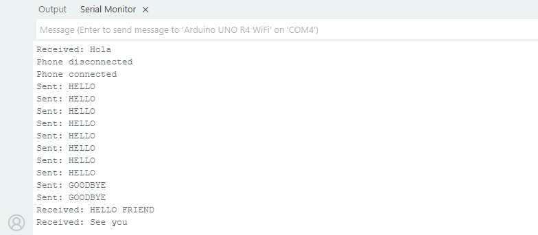
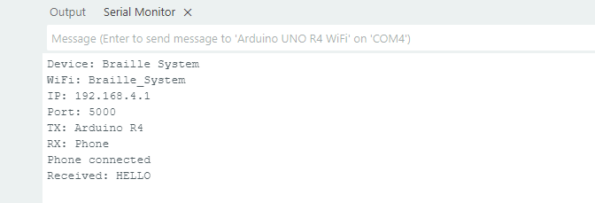
We also tested the communication in the opposite direction from the phone to the Arduino to check the reception of data. For this test we used the Serial Monitor to visualize the information received by the Arduino.
One channel is used to send data from the Arduino and other channel receives information from the connected device.
BLEService brailleService(
  "19B10000-E8F2-537E-4F6C-D104768A1214"
);

BLEStringCharacteristic txCharacteristic(
  "19B10001-E8F2-537E-4F6C-D104768A1214",
  BLERead | BLENotify,
  20
);

BLEStringCharacteristic rxCharacteristic(
  "19B10002-E8F2-537E-4F6C-D104768A1214",
  BLEWrite | BLEWriteWithoutResponse,
  20
);
The name Braille System is assigned to the device.
BLE.setLocalName("Braille System");
BLE.setAdvertisedService(brailleService);

brailleService.addCharacteristic(txCharacteristic);
brailleService.addCharacteristic(rxCharacteristic);

BLE.addService(brailleService);
BLE.advertise();
The data to be sent is stored in currentWord before transmission.
txCharacteristic.writeValue(currentWord);
The received data is stored in lastReceived.
if (rxCharacteristic.written())
{
  lastReceived =
    rxCharacteristic.value();
}
WIFI
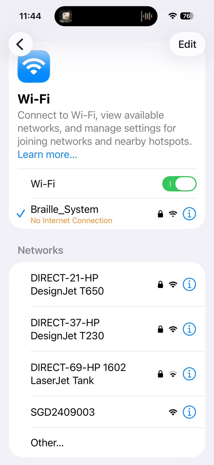
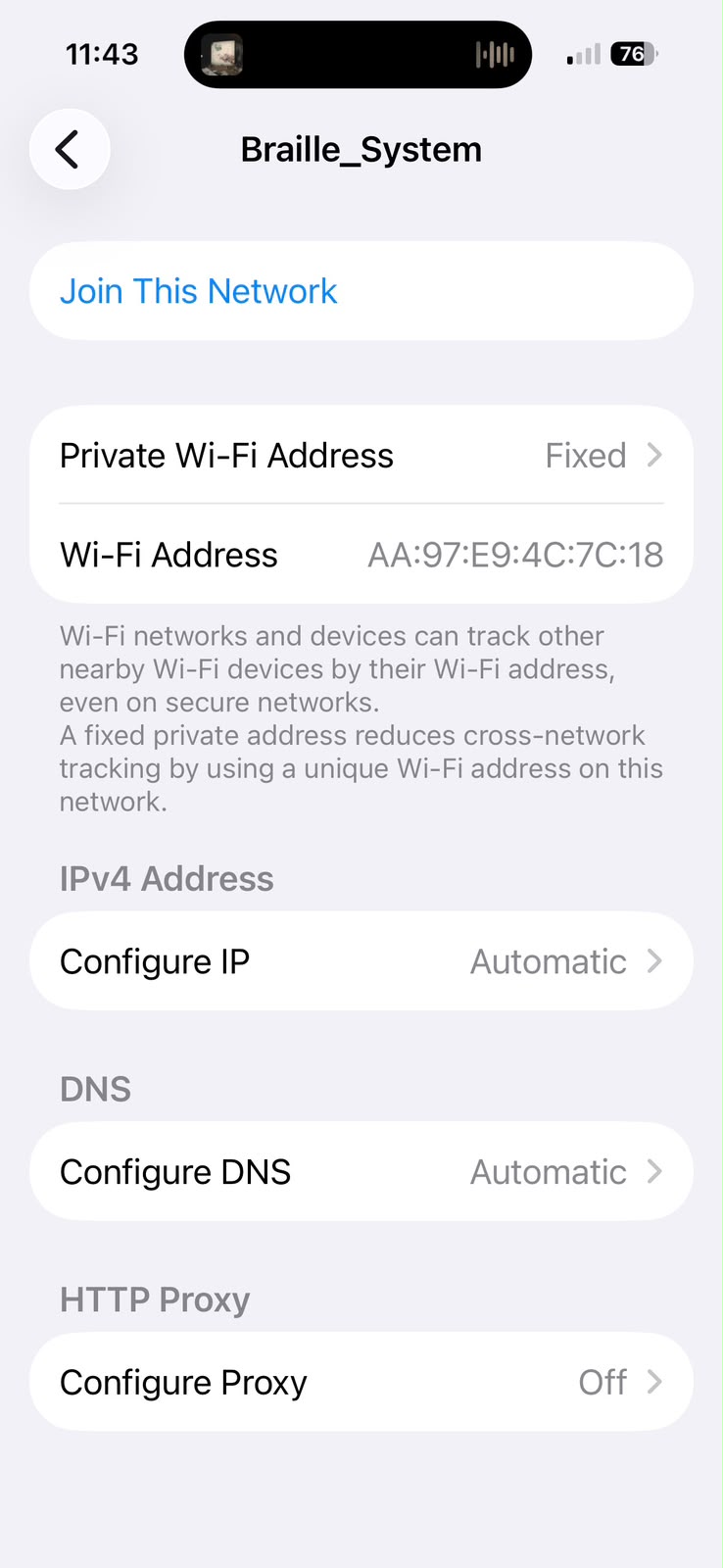
Finally we used two communication protocols over Wi-Fi: TCP and UDP. We created a local wireless network so an Internet connection was not required since the communication occurred directly between the devices.
TCP
TCP establishes a connection between two devices before sending the information so that the data arrives in the same order in which it was sent. If a data does not arrive or arrives with an error the system can send it again.
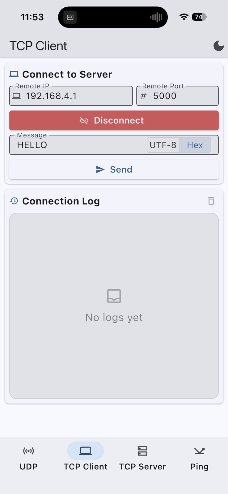
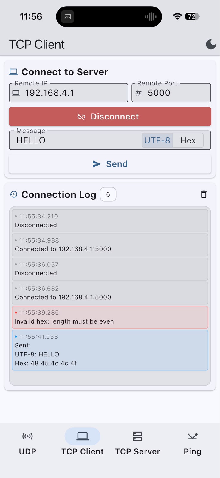
TCP communication between the phone and the Arduino was established using the phone as a TCP client connected to the server through the IP address 192.168.4.1 and port 5000.
Several data transmissions were performed to verify that the connection remained active and that the bytes were received in the same order in which they were transmitted.
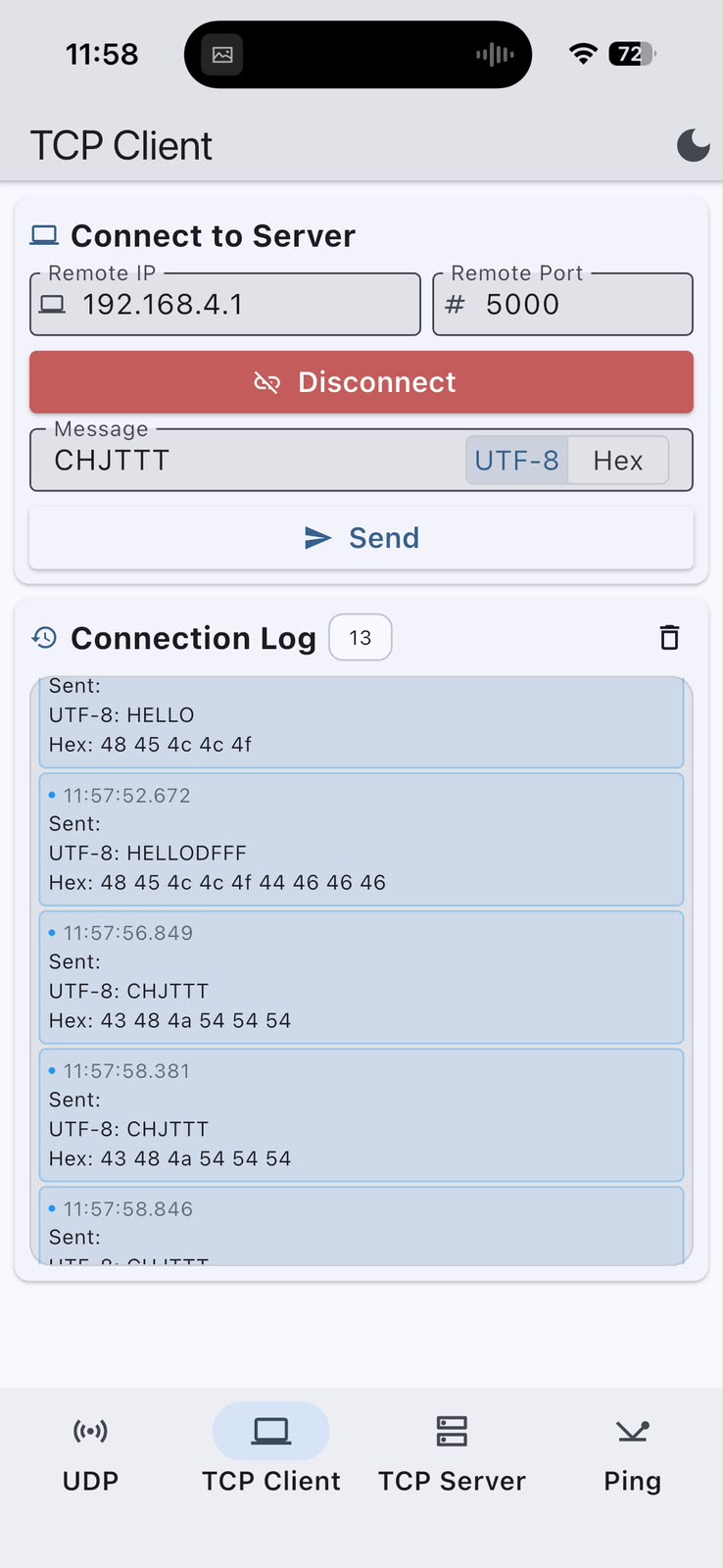
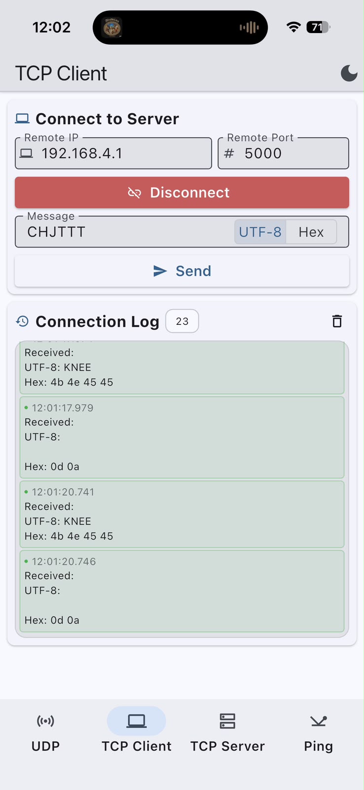
A TCP server is created and a client is used to handle the connected device.
WiFiServer wifiServer(WIFI_PORT);
WiFiClient wifiClient;
The client is stored when a connection is established.
WiFiClient newClient =
  wifiServer.available();

if (newClient)
{
  wifiClient = newClient;
}
The data stored in currentWord is sent to the connected client.
wifiClient.println(currentWord);The received data is read from the connection and can then be stored.
if (wifiClient.available())
{
  char c =
    wifiClient.read();
}
UDP
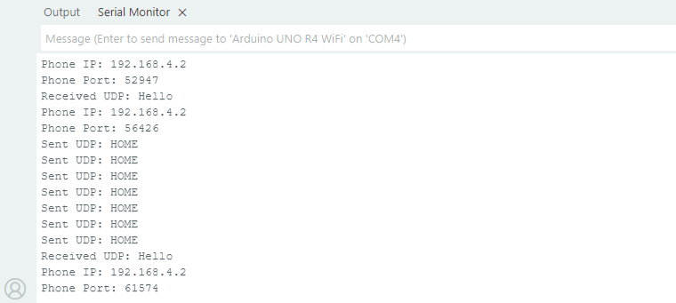
In this test the phone was configured to send datagrams to the Arduino's IP address. Unlike TCP it was not necessary to establish a previous connection before transmitting the data. When the Arduino received the first packet it stored the phone's IP address and port so that it could send data back to the same device.
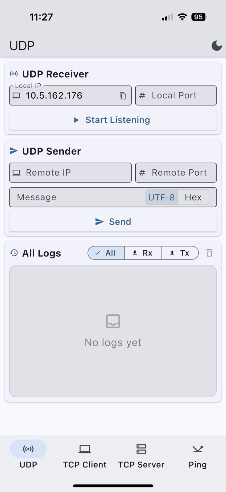
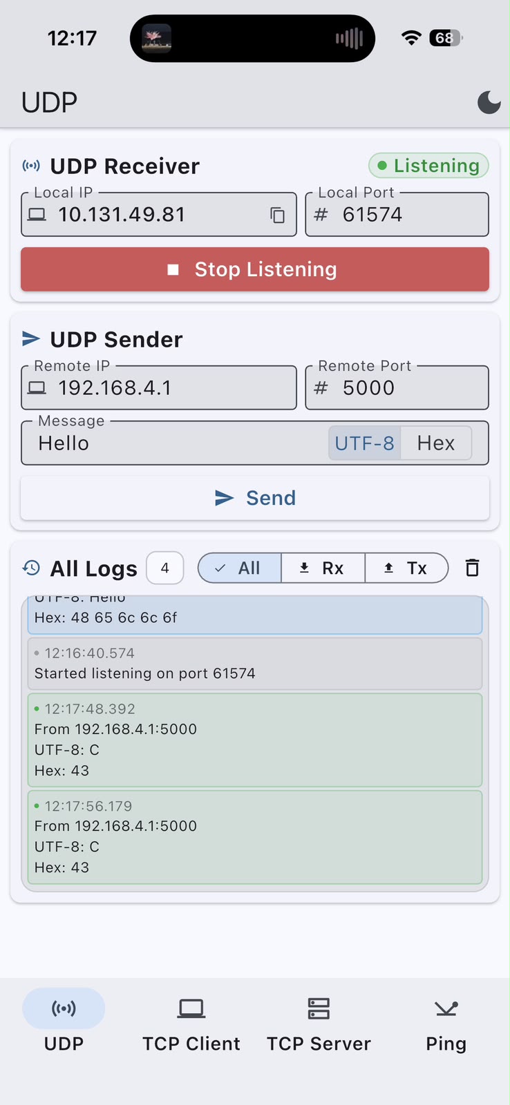
UDP communication is created and started on the defined port.
WiFiUDP wifiUDP;

wifiUDP.begin(WIFI_PORT);
The IP address and port of the remote device define the destination of the packet. The data stored in currentWord is then added and sent.
wifiUDP.beginPacket(
  udpRemoteIP,
  udpRemotePort
);

wifiUDP.print(currentWord);
wifiUDP.endPacket();
The program checks whether a new packet has been received and reads its data.
int packetSize =
  wifiUDP.parsePacket();

if (packetSize > 0)
{
  char packetBuffer[81];

  int len =
    wifiUDP.read(
      packetBuffer,
      80
    );
}
The IP address and port of the device that sent the packet are also stored.
udpRemoteIP =
  wifiUDP.remoteIP();

udpRemotePort =
  wifiUDP.remotePort();