Mechanical Design
Stepper Motor
Mechanical System
Fundamentals
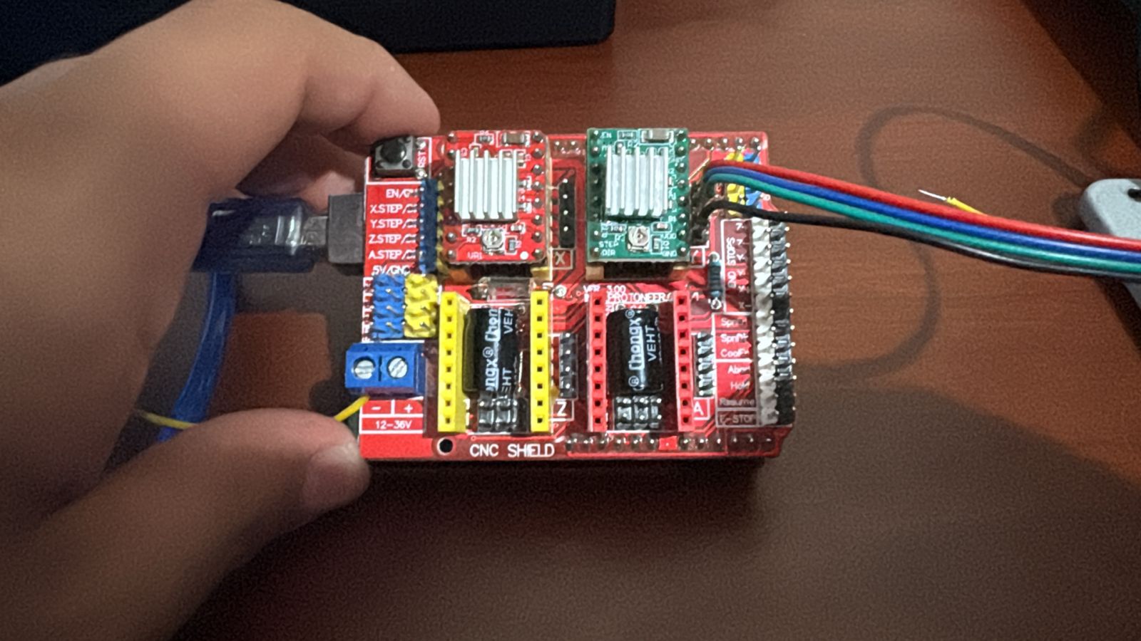
To develop our project, we will use a CNC Shield and an A4988 stepper motor driver to regulate the voltage and current required to drive the step-by-step.
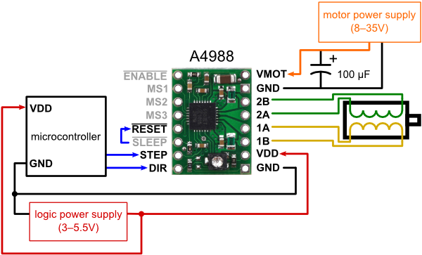
The A4988 is designed to operate bipolar stepper motors in full-, half-, quarter-, eighth-, and sixteenth-step modes, with an output drive capacity of up to 35 V and ±2 A.
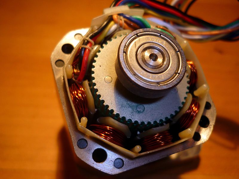
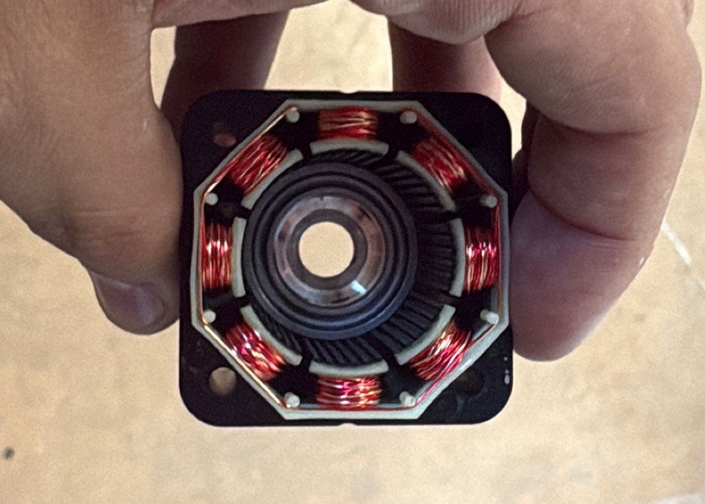
The 17PM-K049BP11CN is a bipolar industrial stepper motor that does not rotate continuously when voltage is applied, as it requires a driver to activate its two internal coils in a specific order.
| Pin | Coil | Driver |
|---|---|---|
| Pin 1 | Coil A (-) | A- / 1B |
| Pin 3 | Coil A (+) | A+ / 1A |
| Pin 4 | Coil B (+) | B+ / 2A |
| Pin 6 | Coil B (-) | B- / 2B |
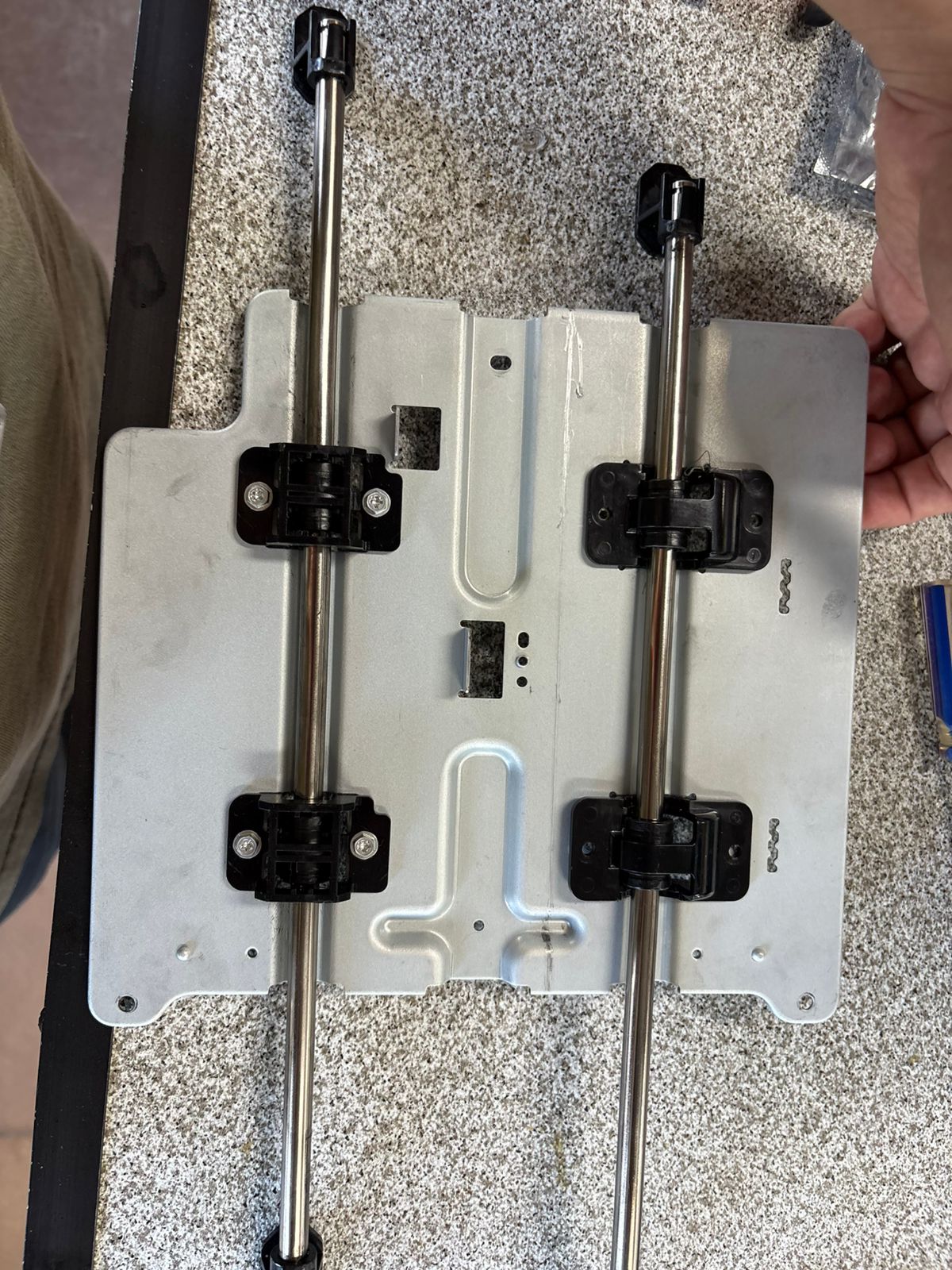
We will use these smooth rods and a carriage to act as the linear guide for the motor's movement.
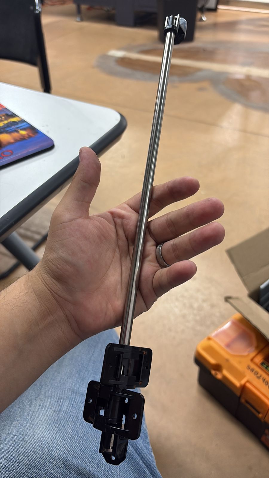
These guides are part of a mechanism we found. We will use them to implement our own mechanism, starting with the basic concept of moving just this sliding carriage.
Design
The first step is to fabricate the bases that support the platforms for both axes.
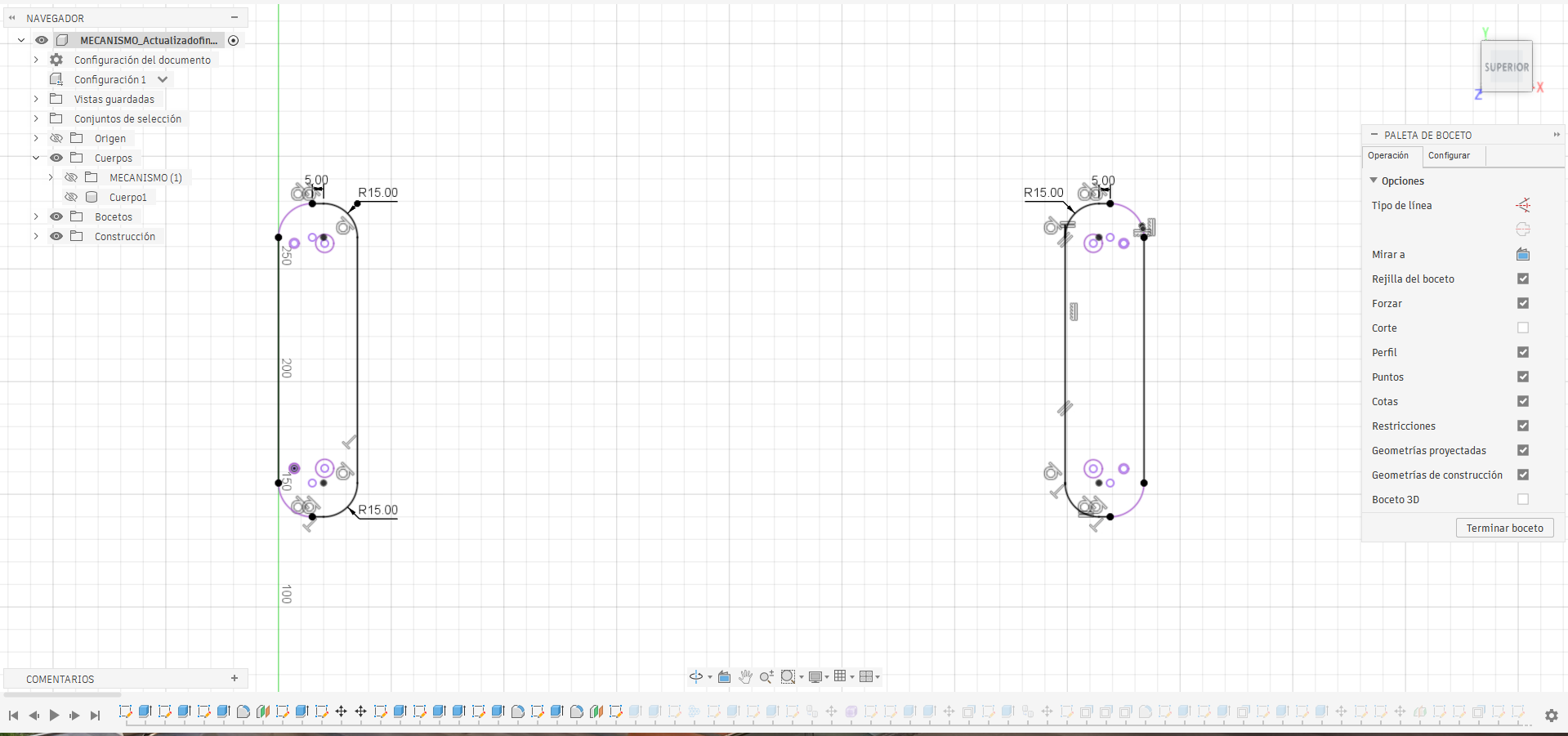
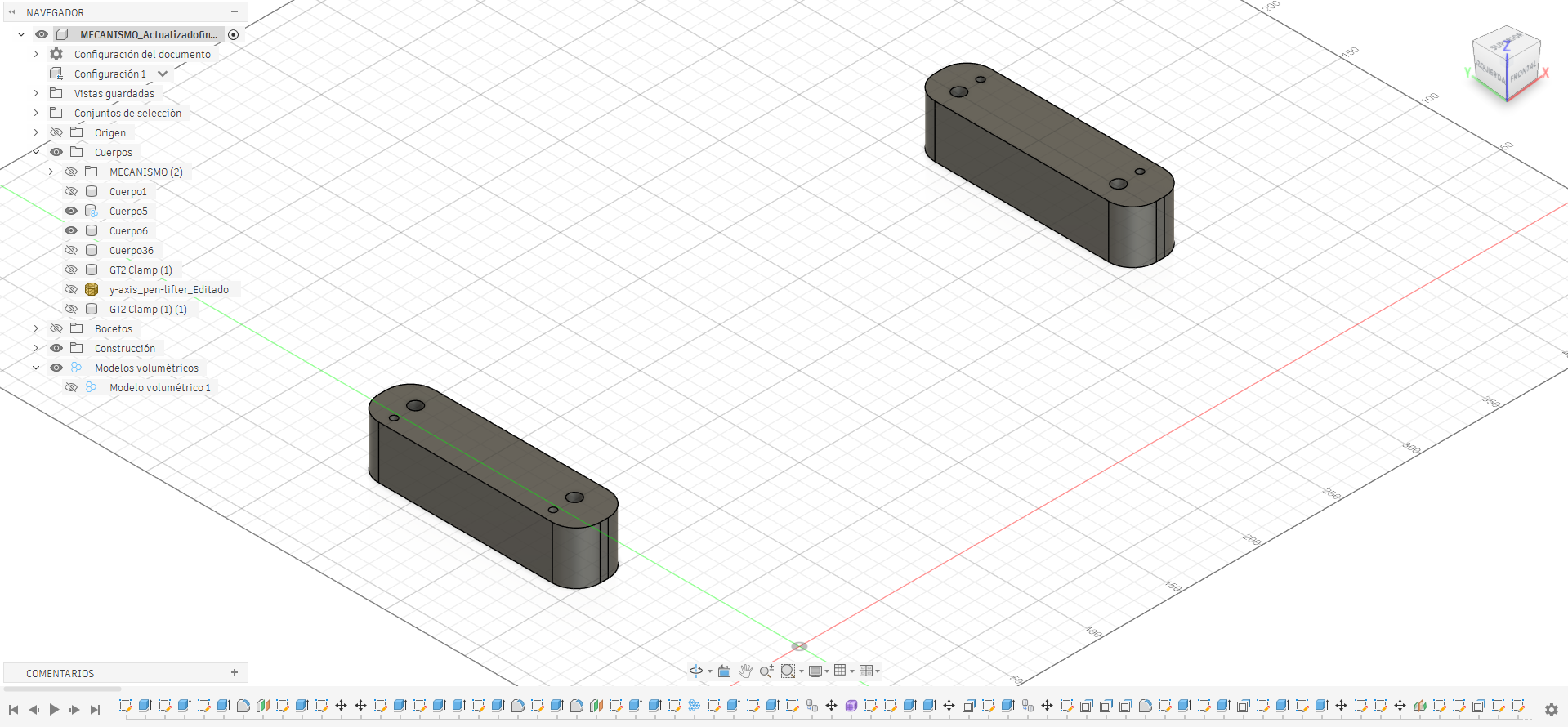
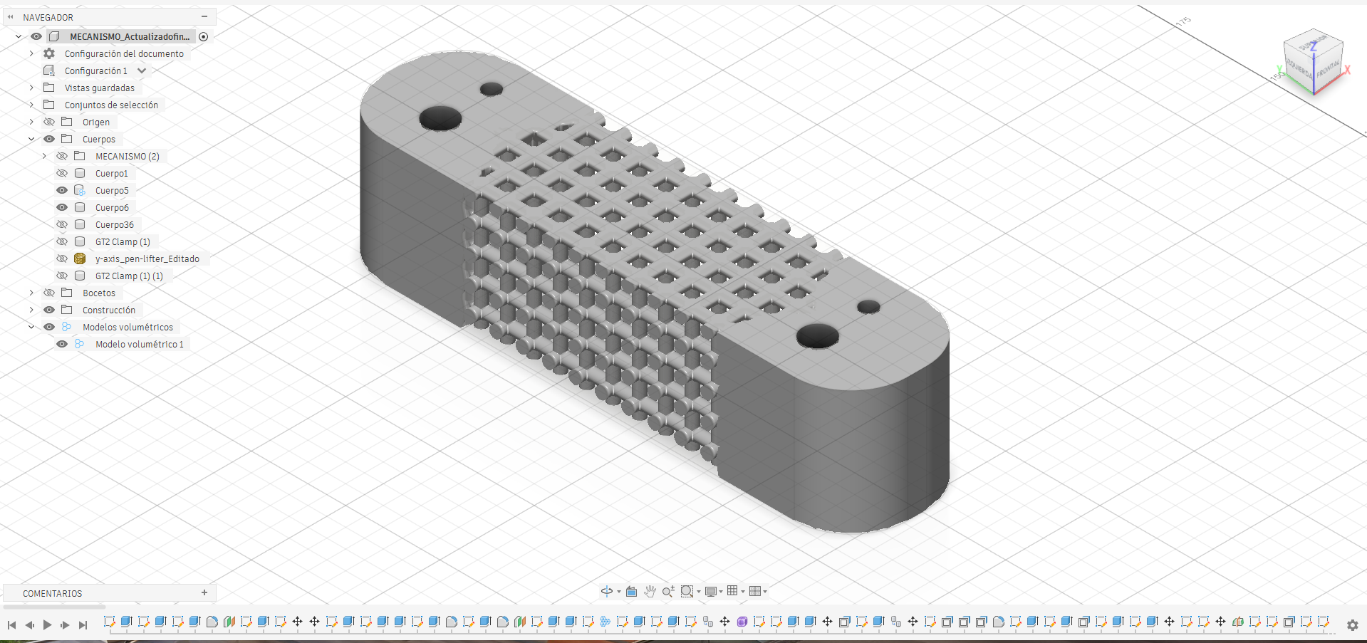
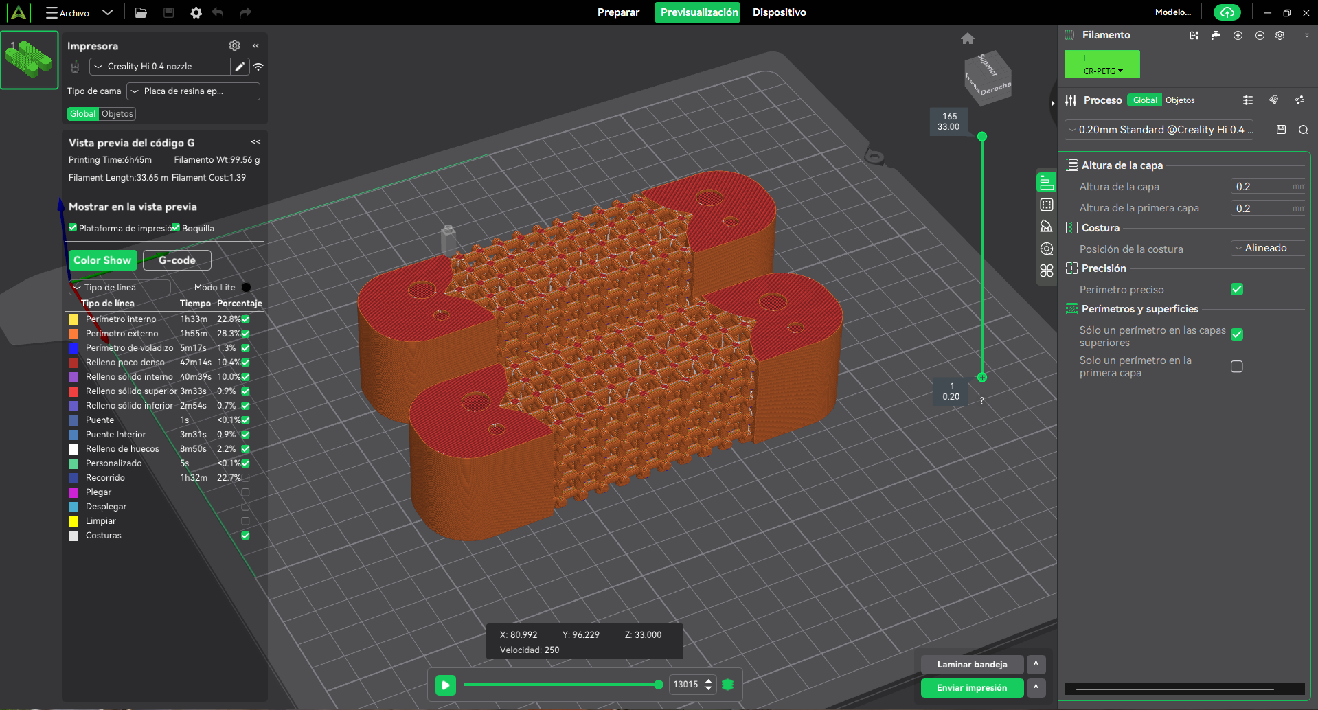
In this design, I integrate a volumetric lattice structure into the model to minimize material usage and ensure the internal framework provides functional structural support.
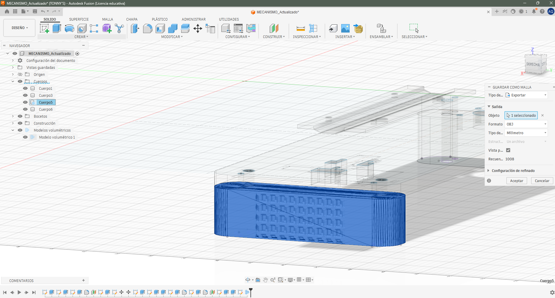
Once the bases are ready, record the key measurements to define the dynamic movement of the mechanism and design the complementary parts.
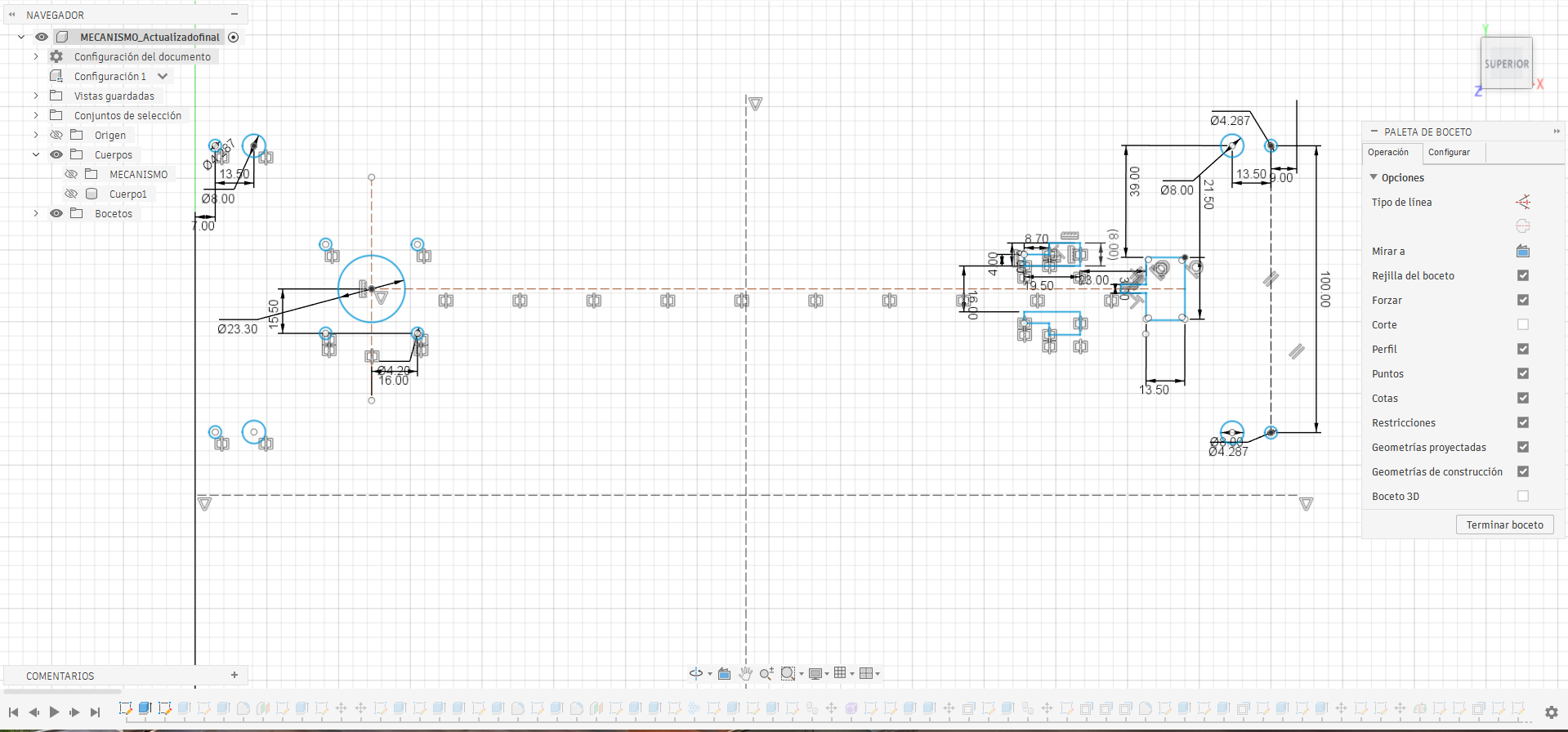
With both designs complete, assemble the first stage of the mechanism.
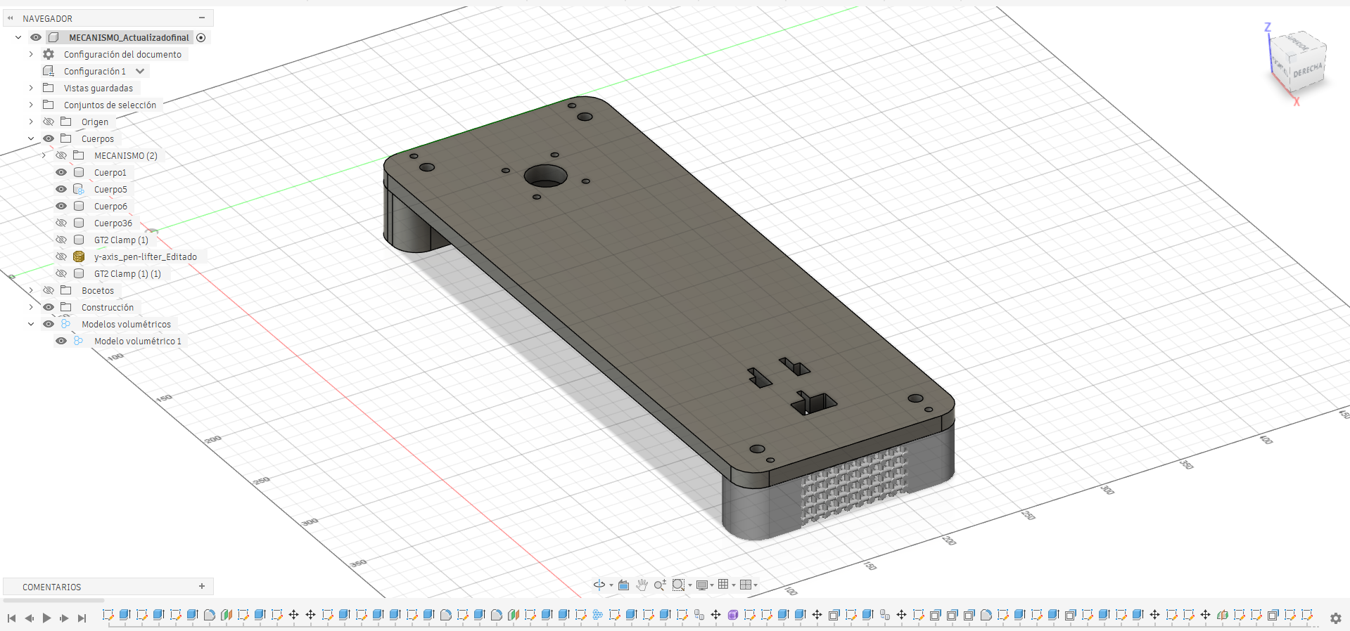
At this stage, I worked on the X-axis carriage. Before designing the part, I measured the repurposed mechanism to ensure proper alignment with its guide rails.
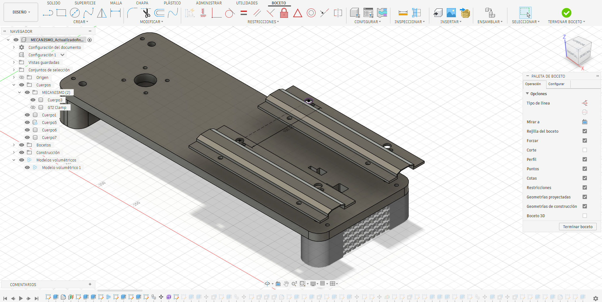
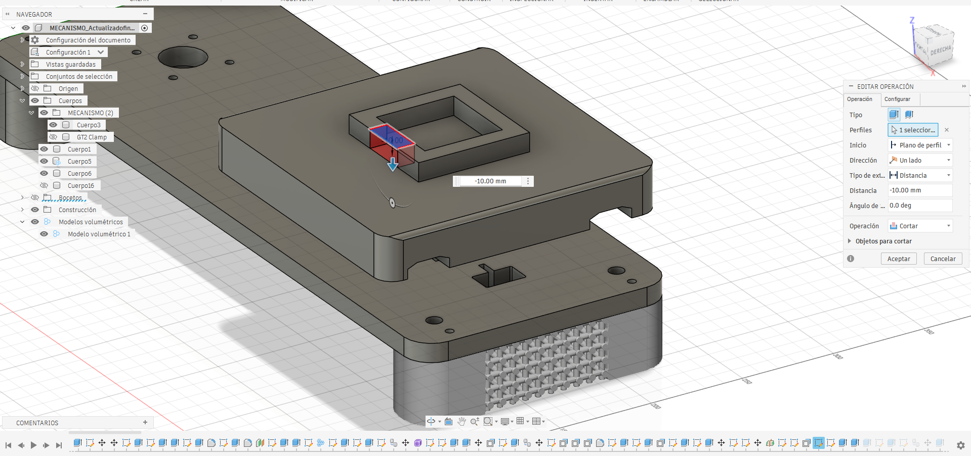
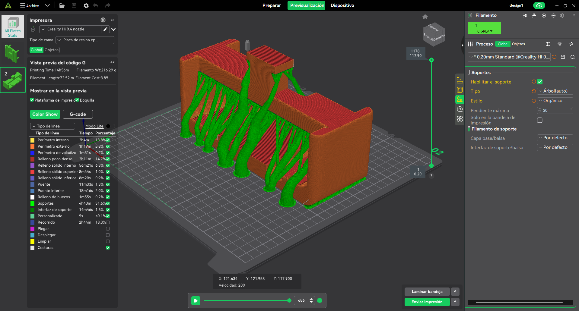
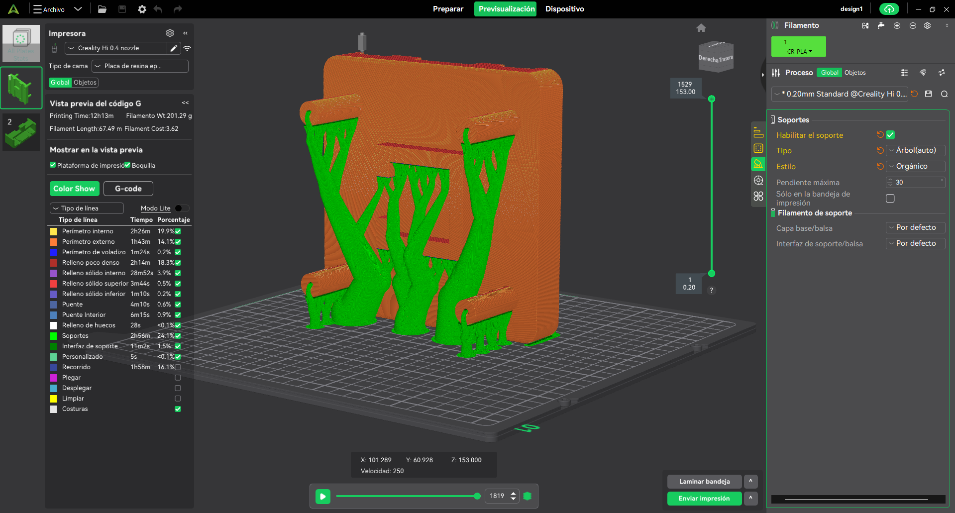
For the second stage of the mechanism, focus on the Y-axis. Use a lightweight material that meets all structural requirements to avoid adding excess mass that could compromise the system's dynamics.
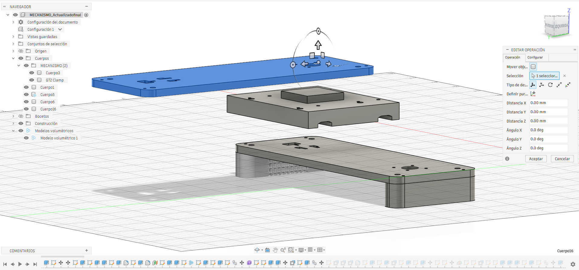
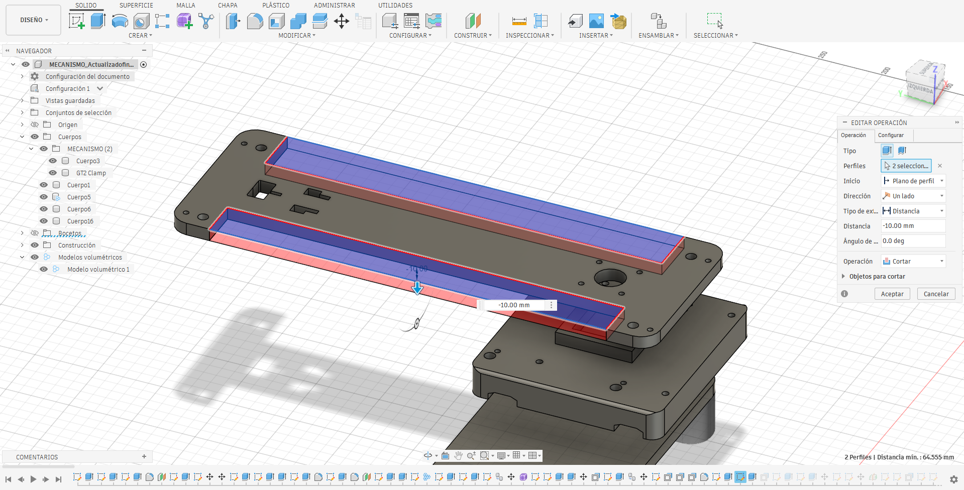
I almost forgot add structural pillars to connect both platforms LOL.
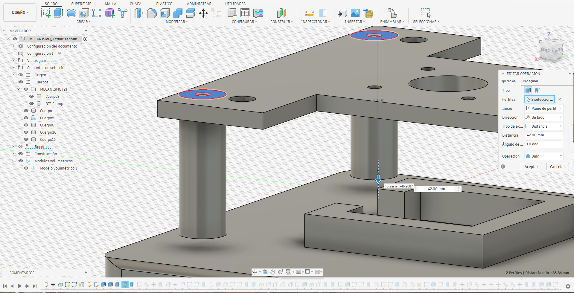
Finally, assemble the pen holder mechanism. Alternative toolhead designs may be used, as long as they comply with the linear guide specifications of the axes.
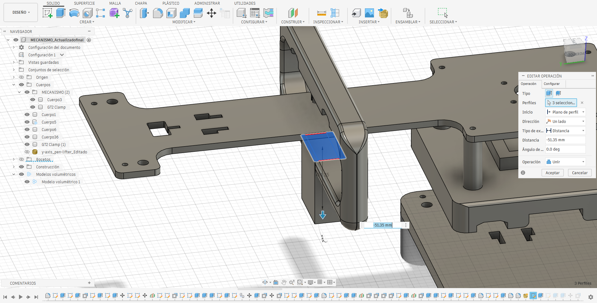
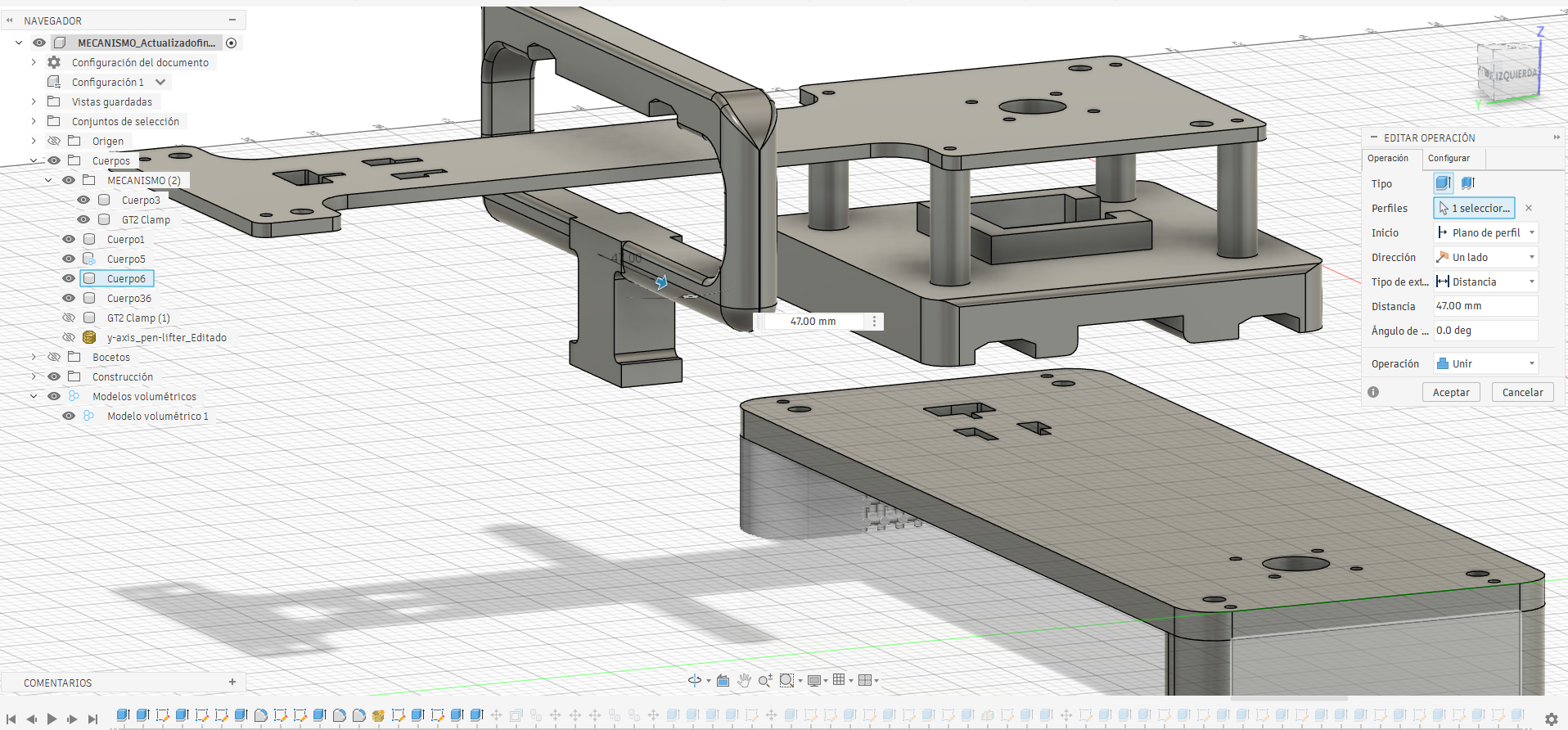
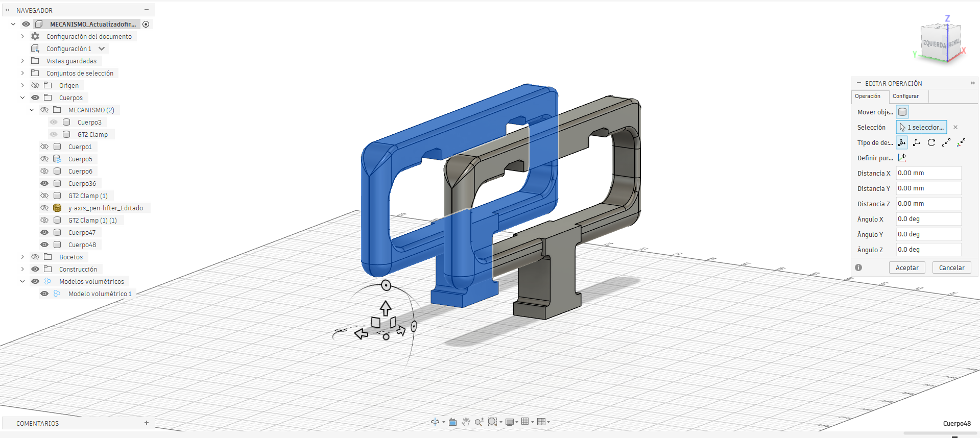
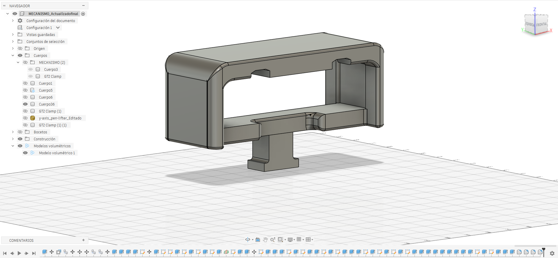
At this point, we completed the assembly of the primary base framework.
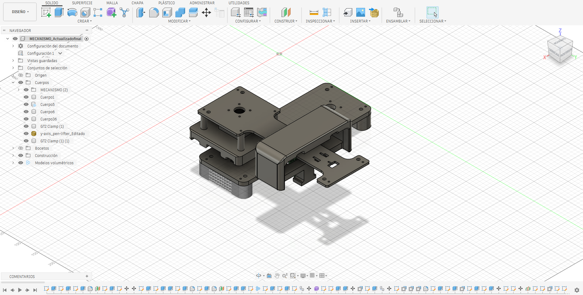
Linear guide dimensions dictated the base geometry, while 3D scanning was leveraged to quickly reverse-engineer non-critical parts.
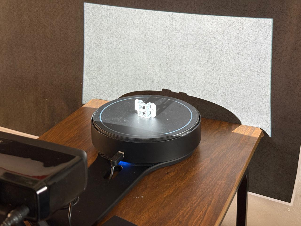
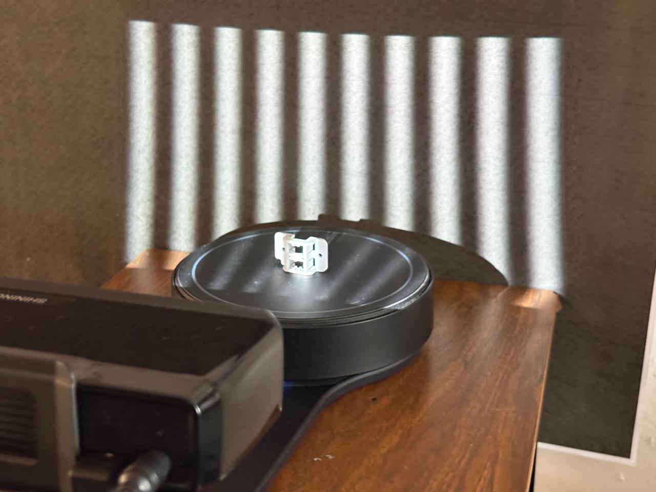
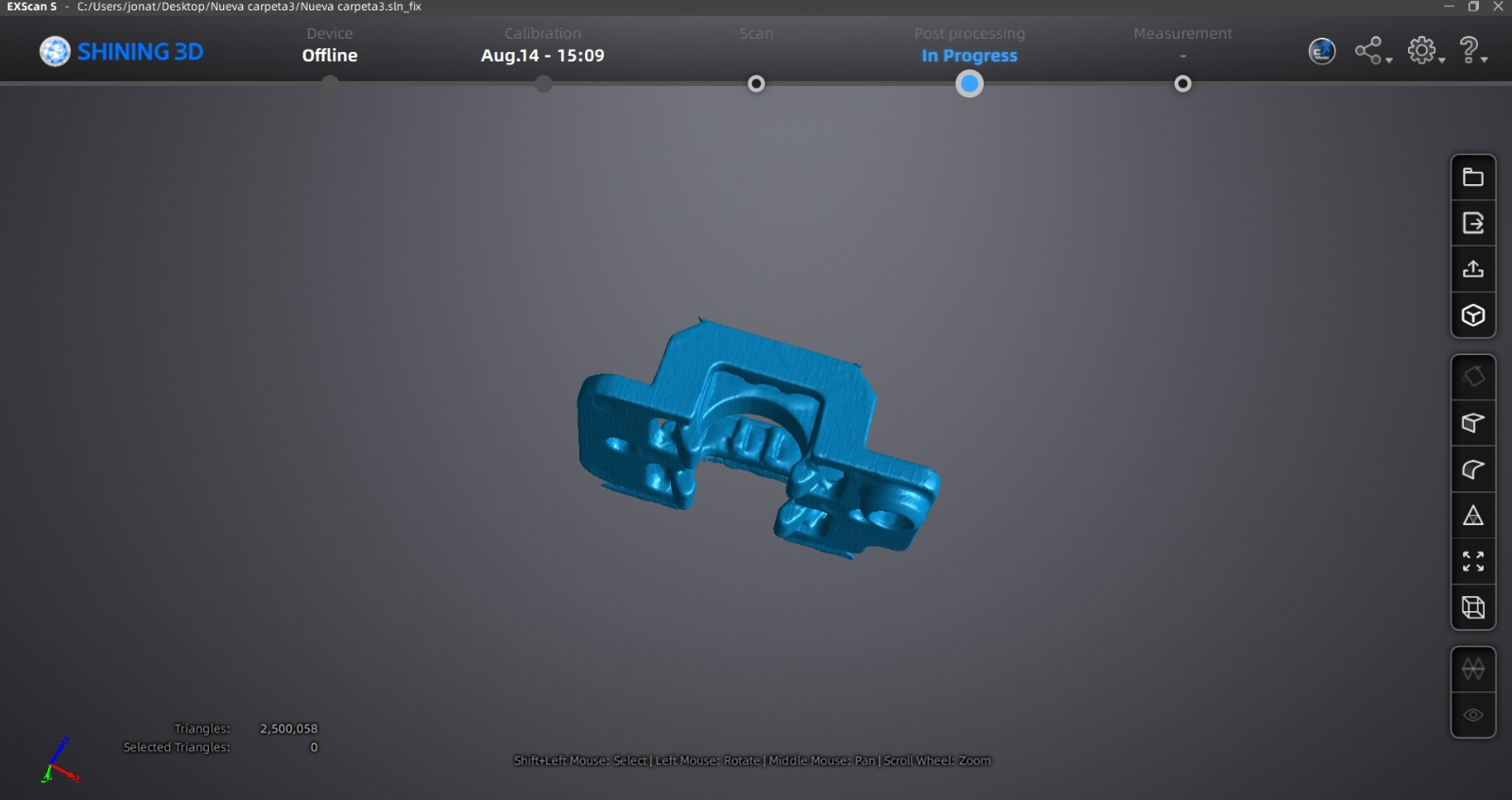
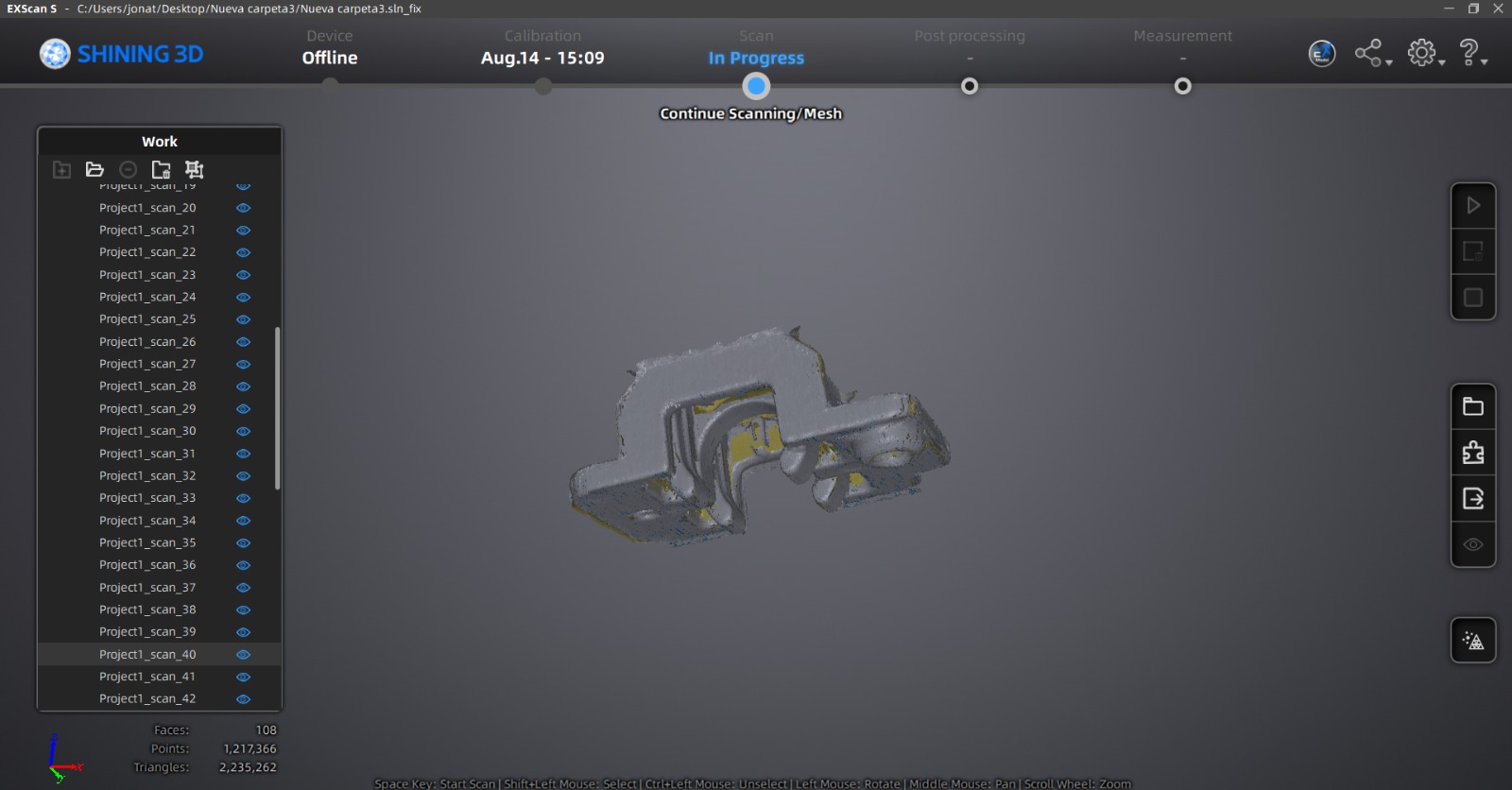
Also a post-processing of the parts to remove imperfections from the scan.
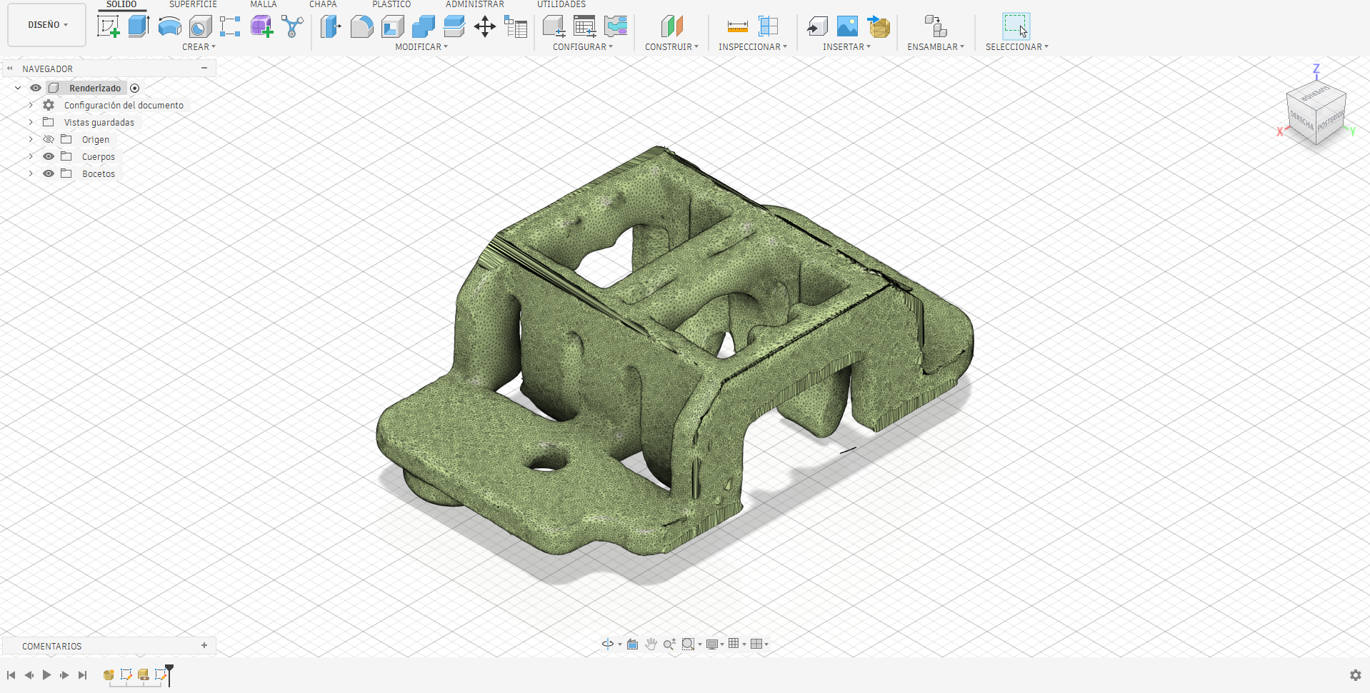
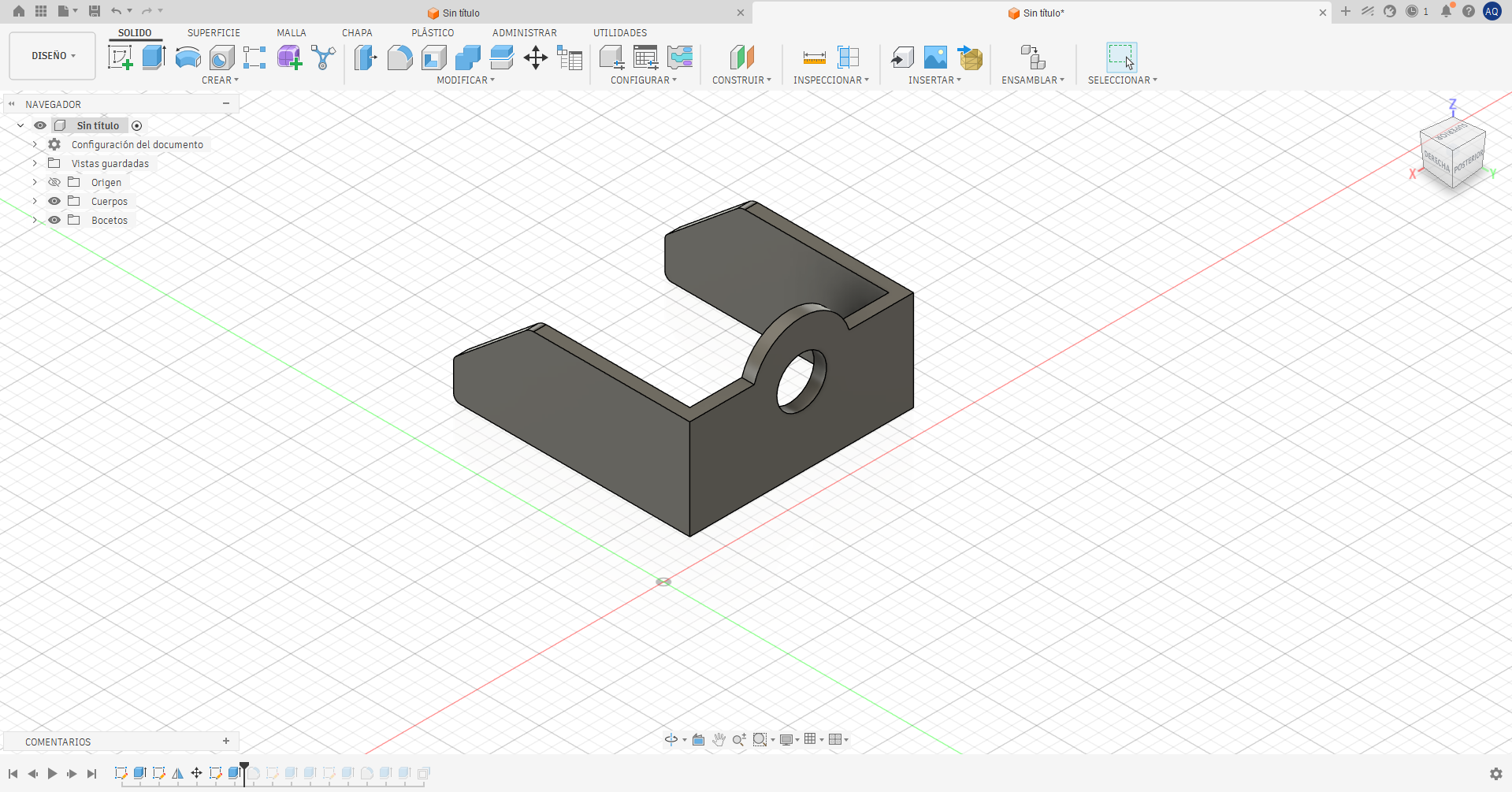
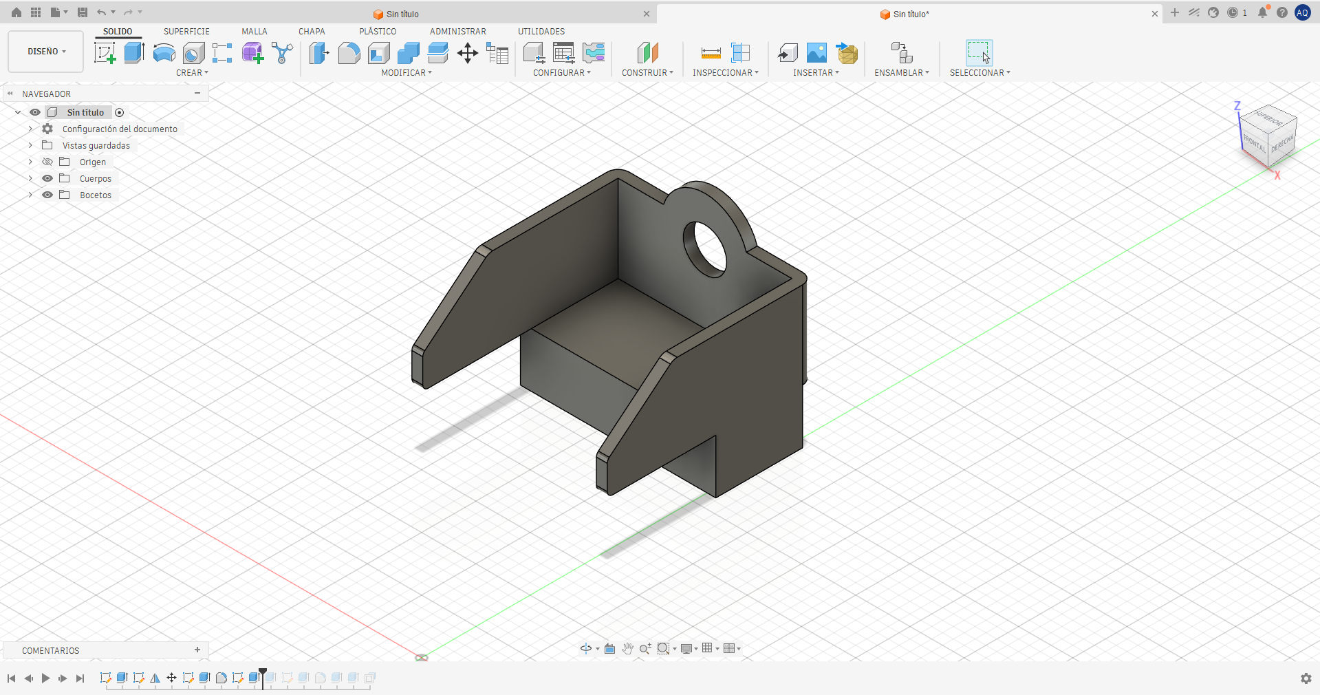
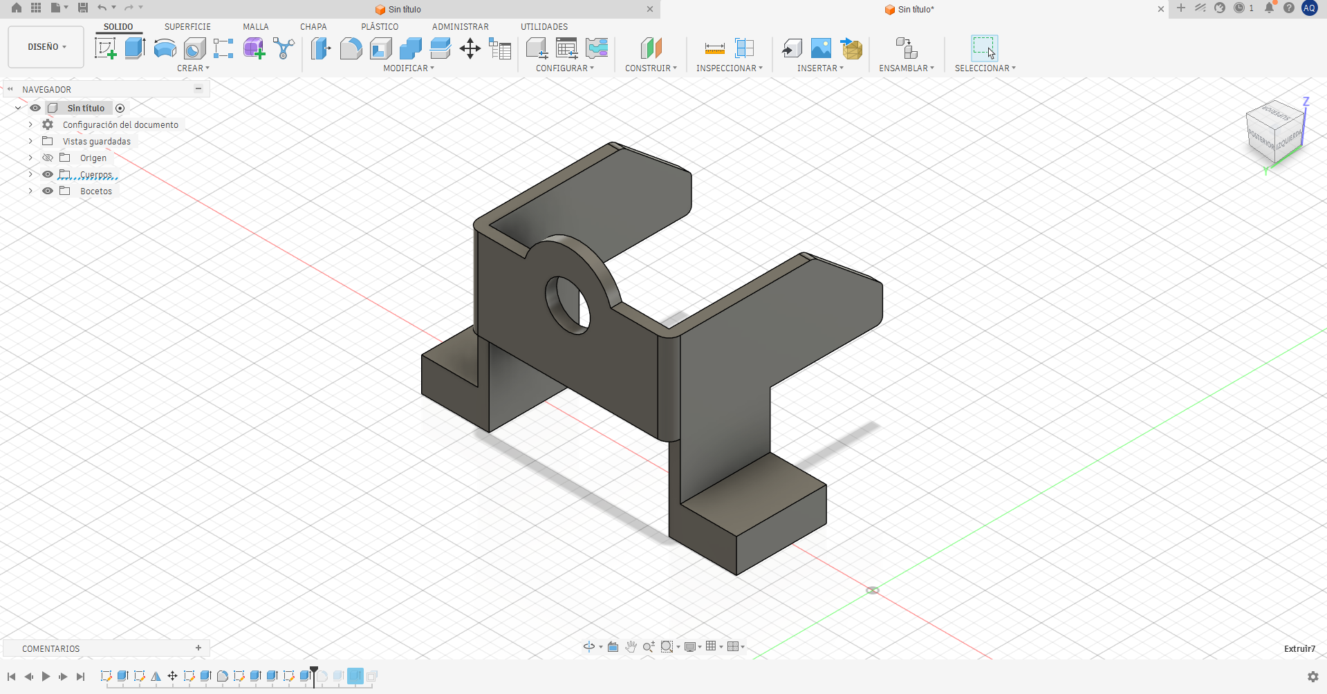
Another of the parts that make up the system works as support for the gear, allowing it to rotate on its own axis. In this way, the movement generated by the motor is transmitted to the gear and subsequently to the linear guide system, causing the displacement of the mechanism.
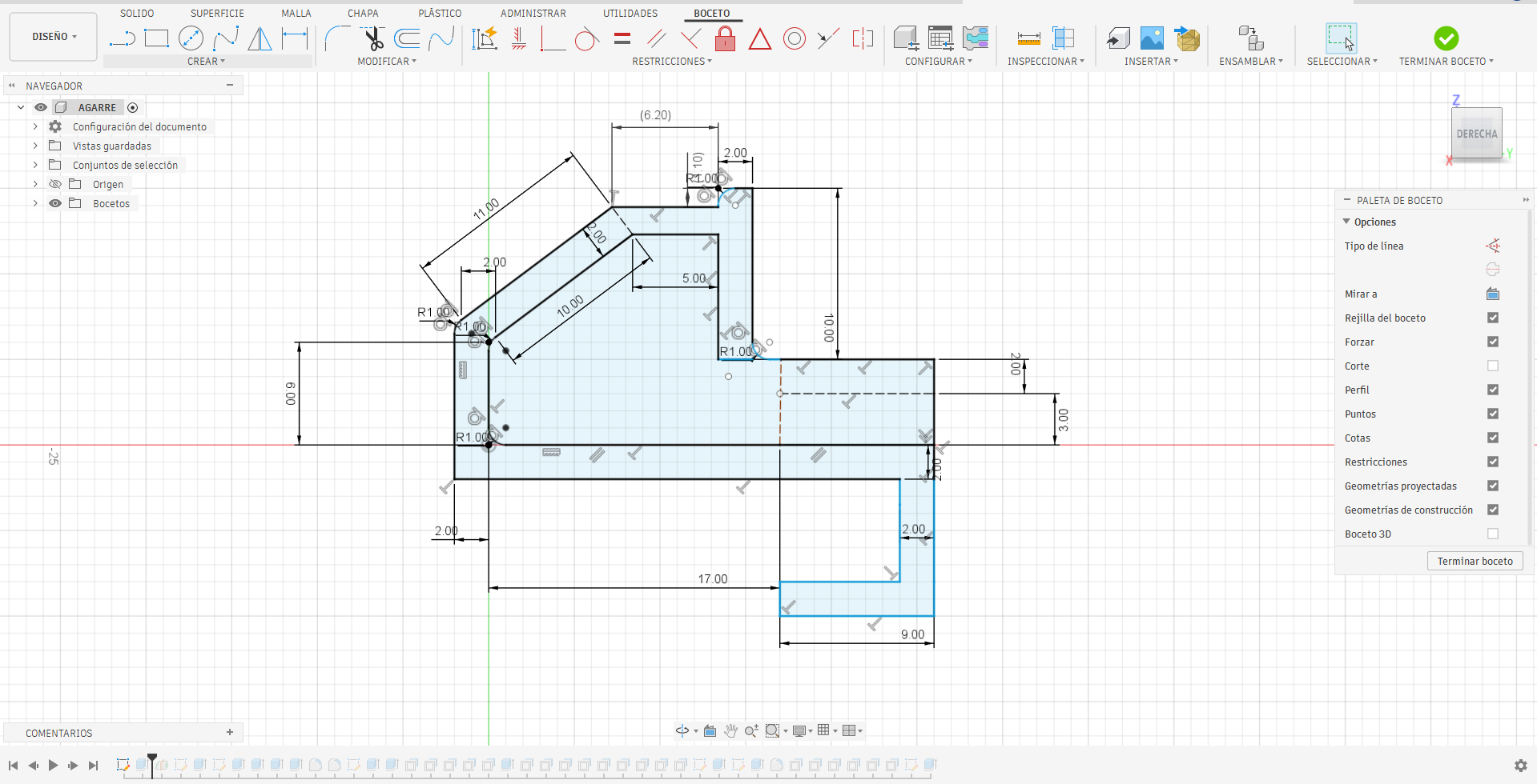
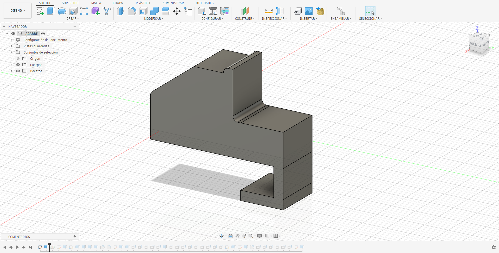
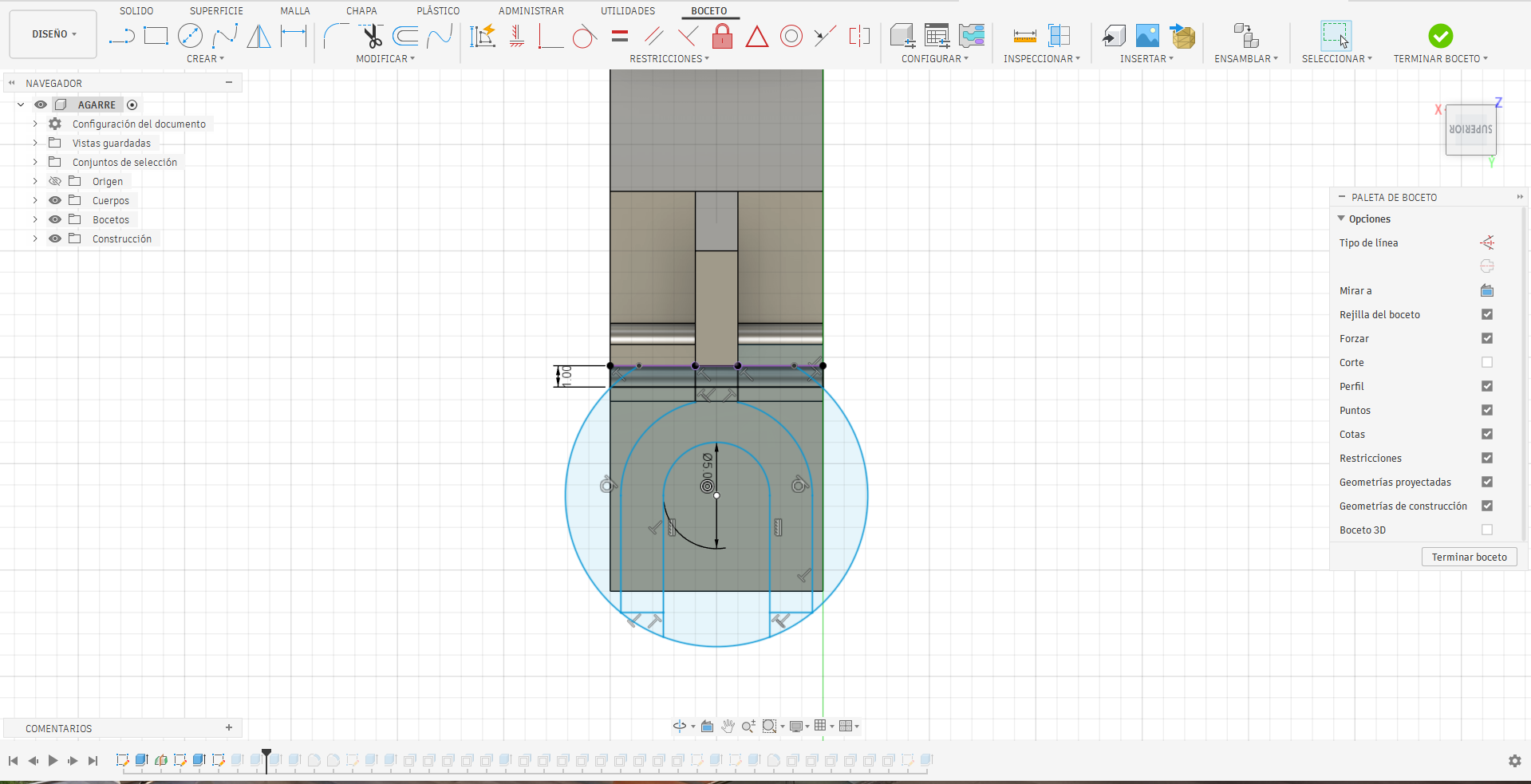
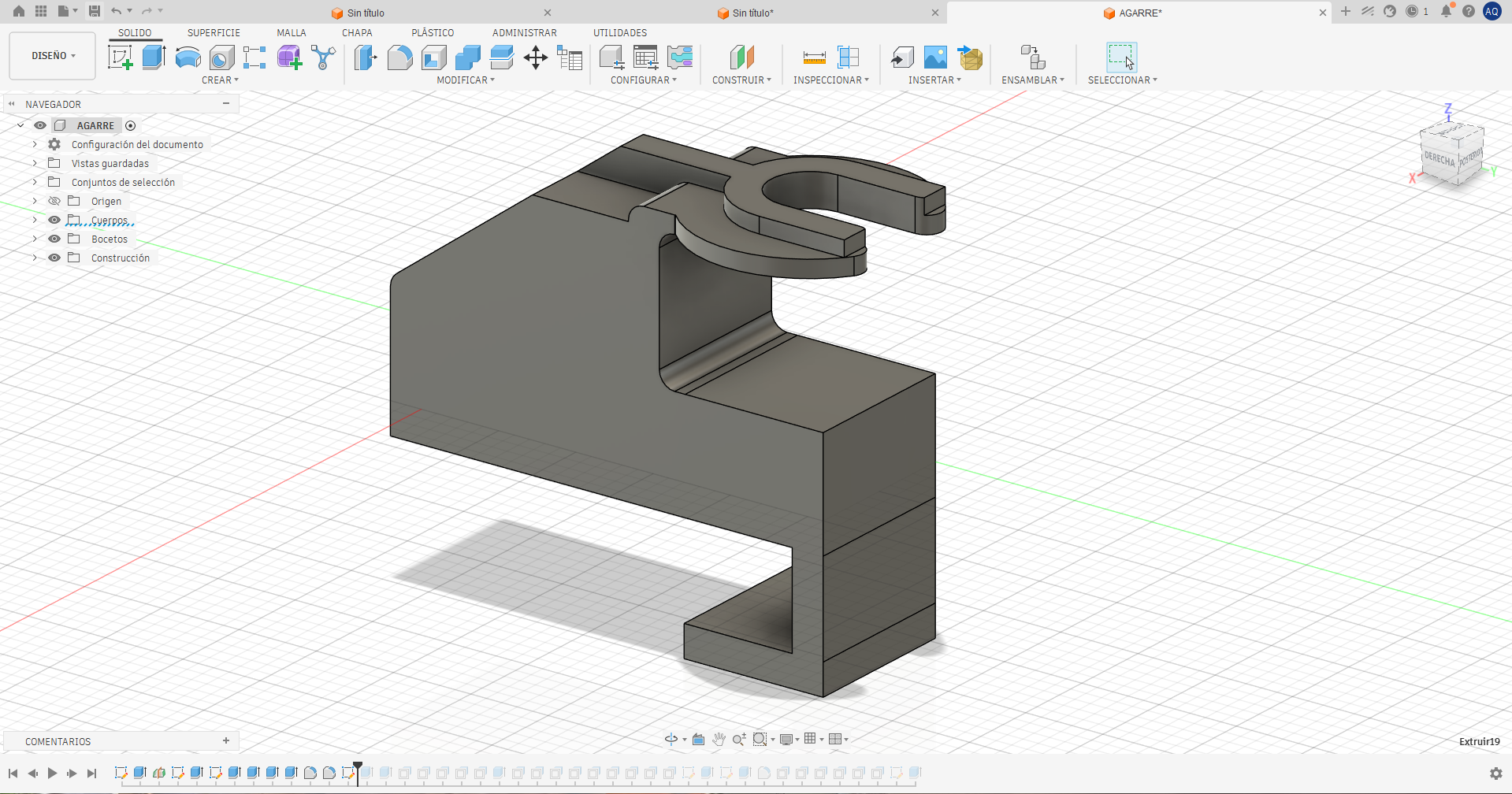
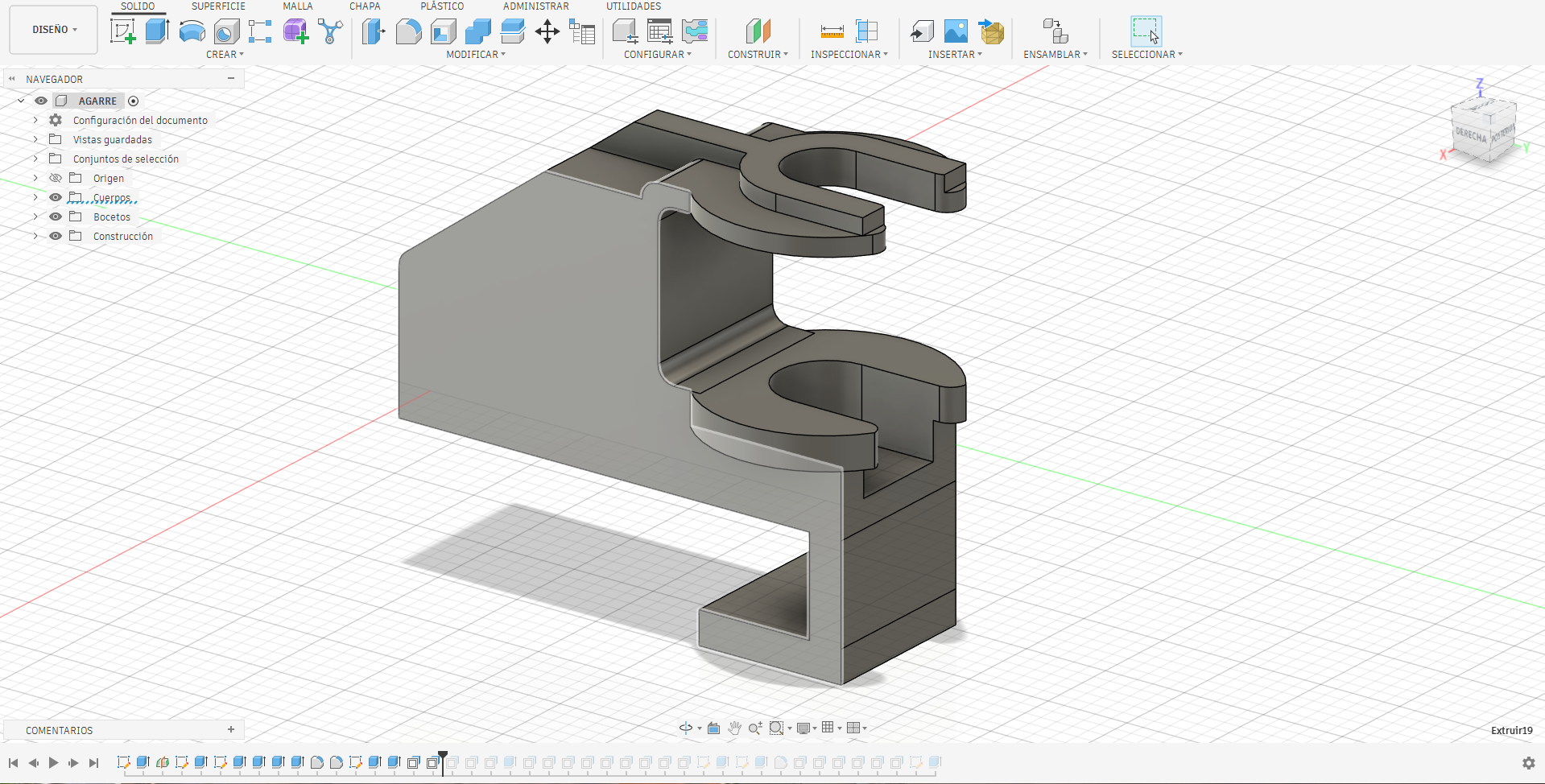
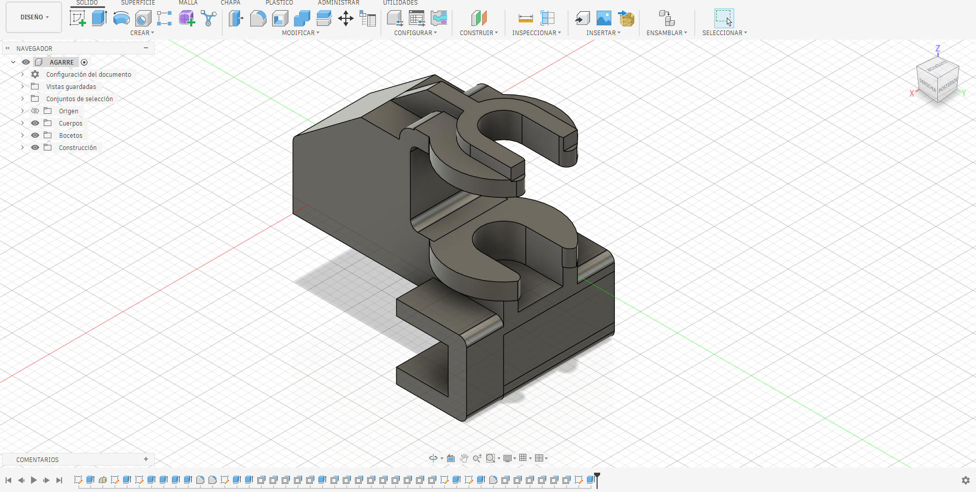
This piece complements the previous support and has the function of tensioning the timing Belt. By means of a screw, the part can move and push the support, progressively increasing the tension of the belt.
Fabrication
One of the pieces is exported in DXF format. However, one of the drawbacks of Fusion 360 is that it can generate overlapping vectors for the same piece. An alternative is to export it in DWG format and organize each piece as a separate element.
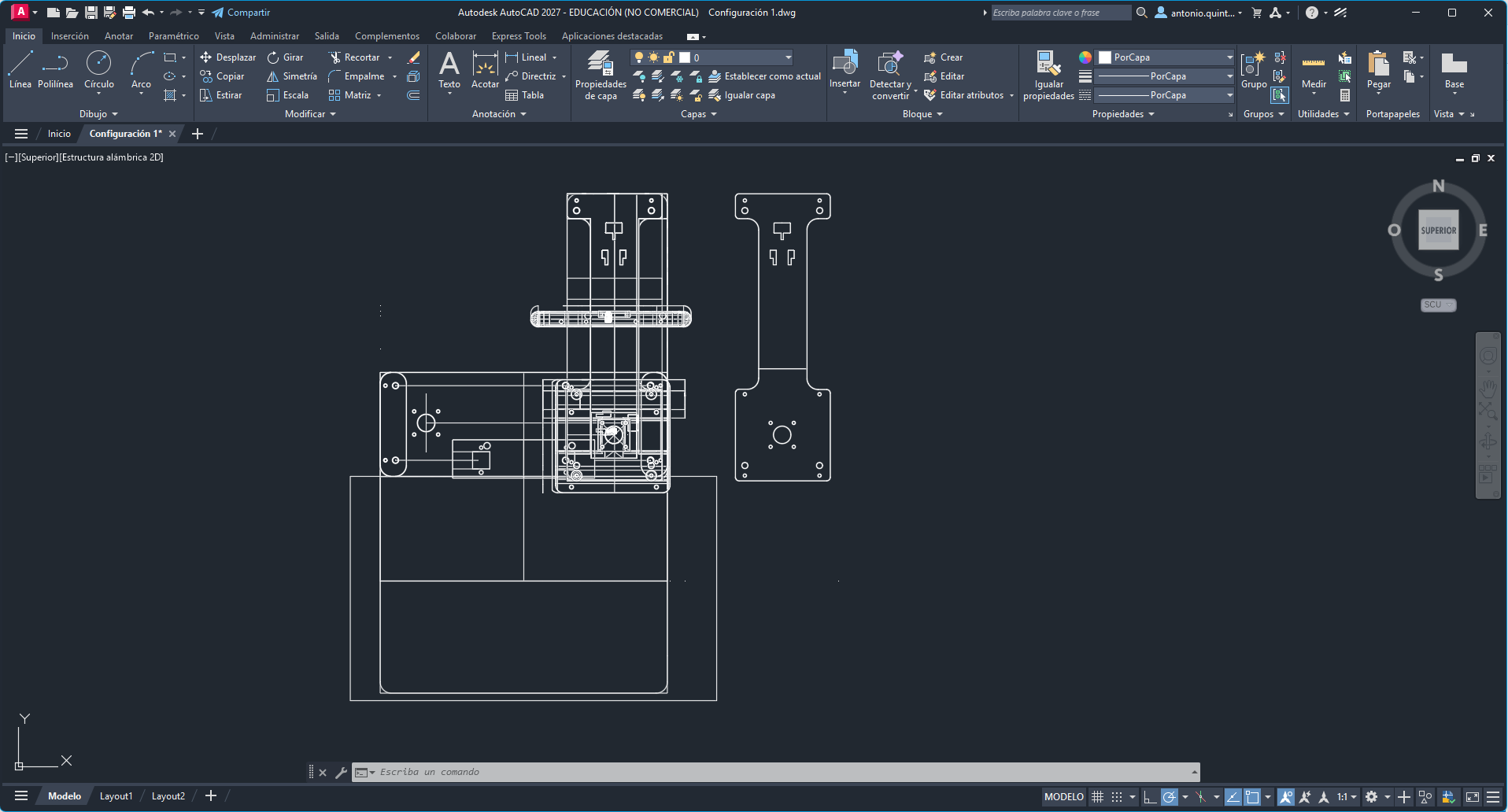
This way, we have our file cleaned and ready for laser cutting.
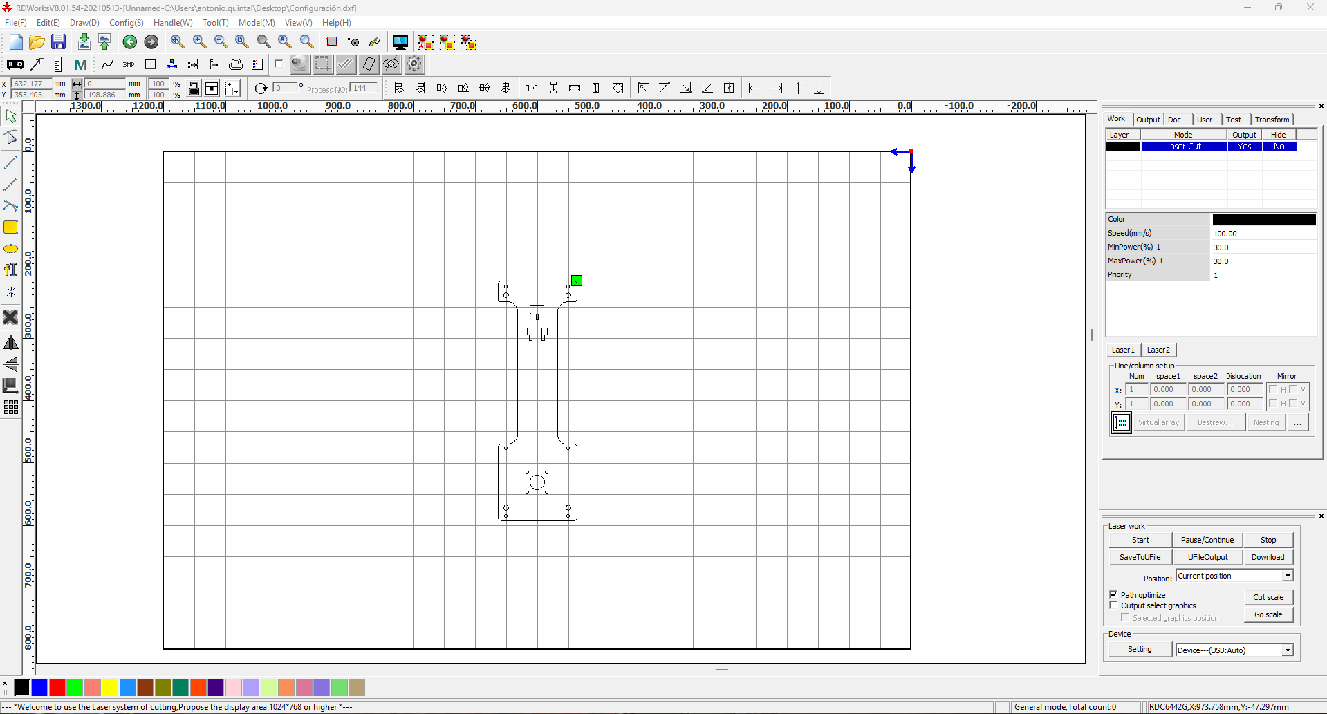
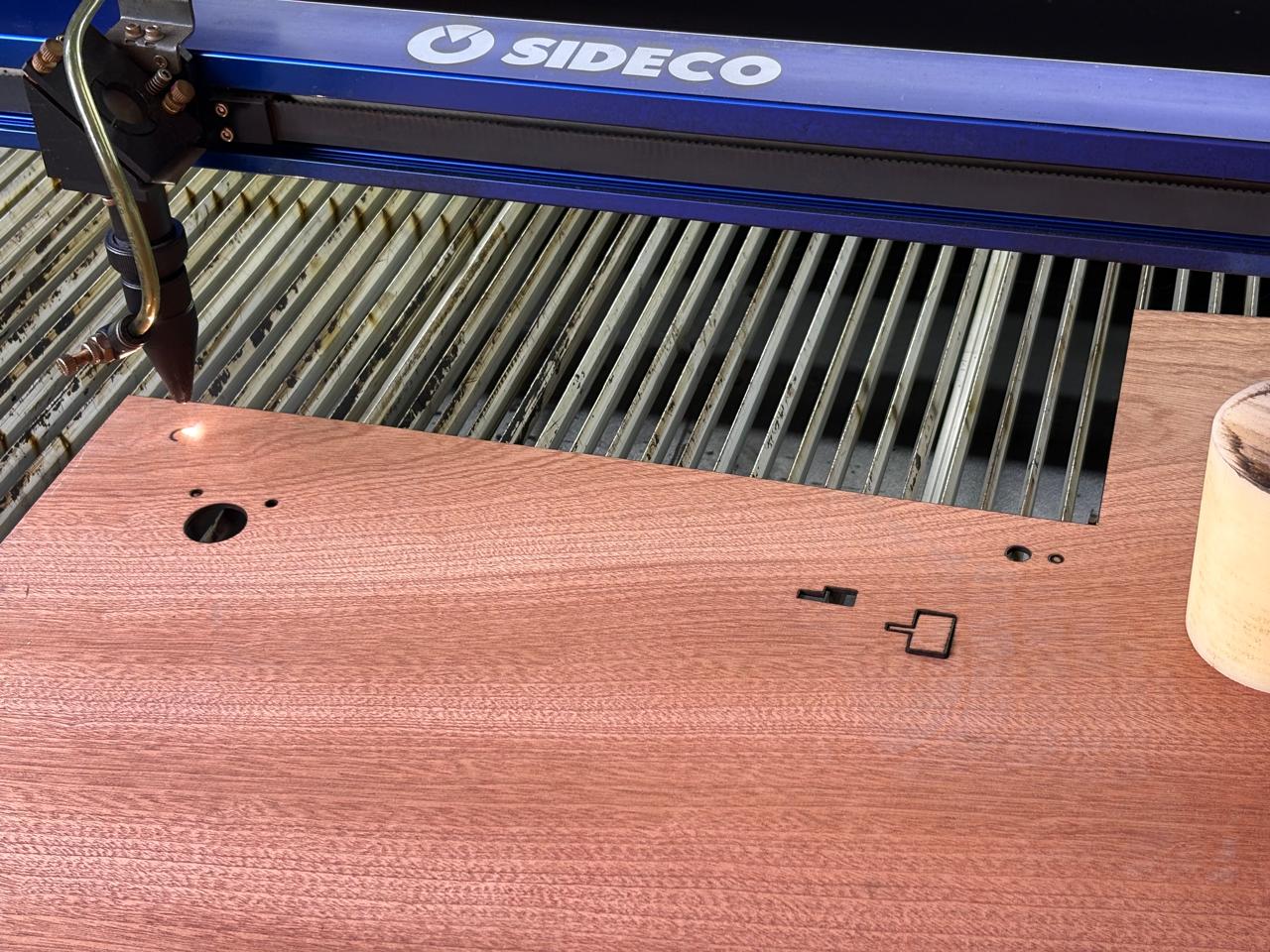
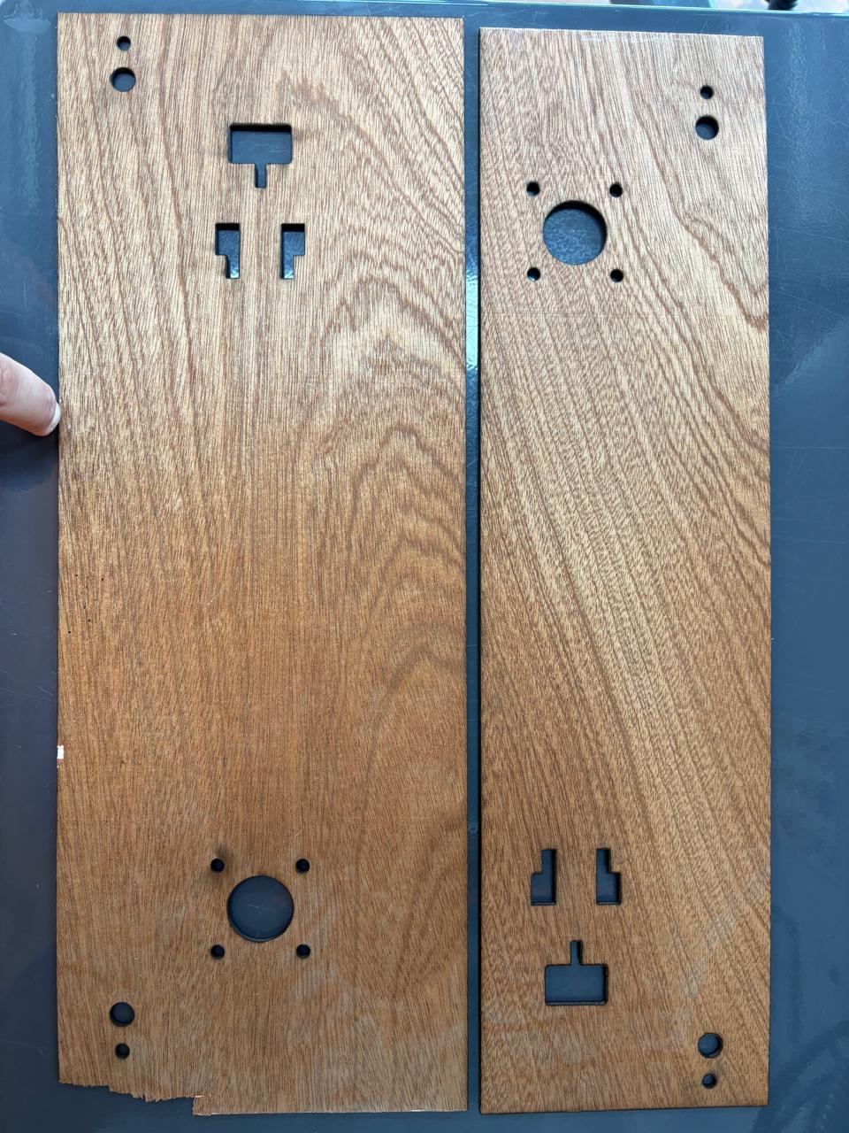
Some material thickness tests.
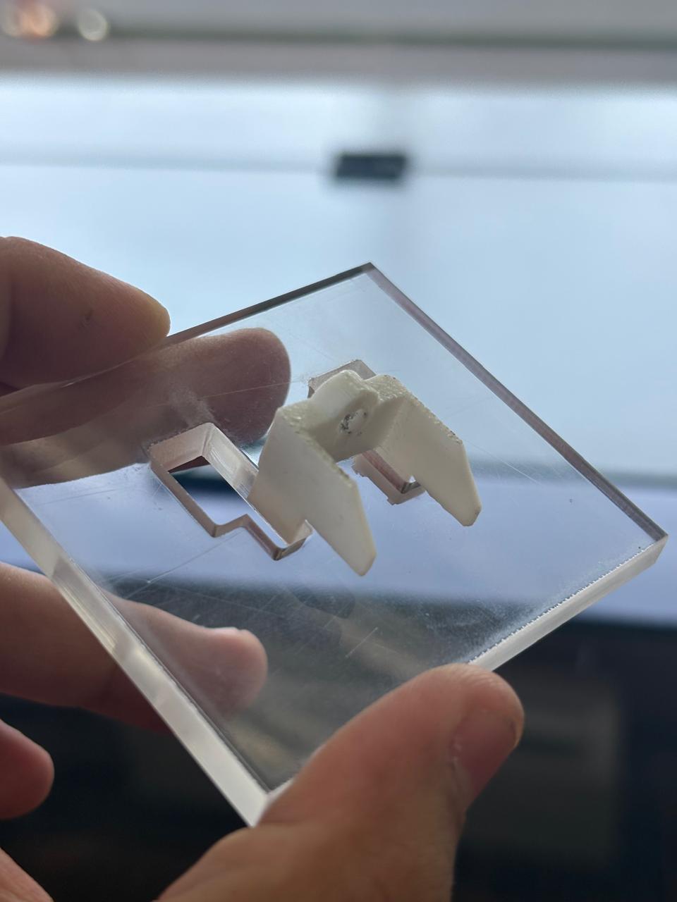
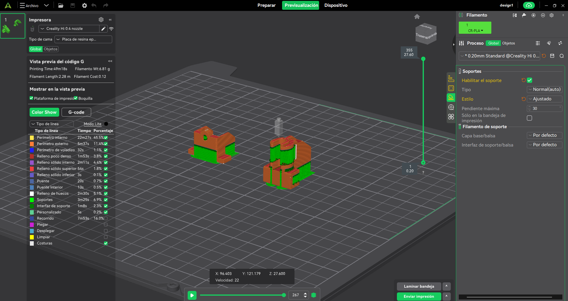
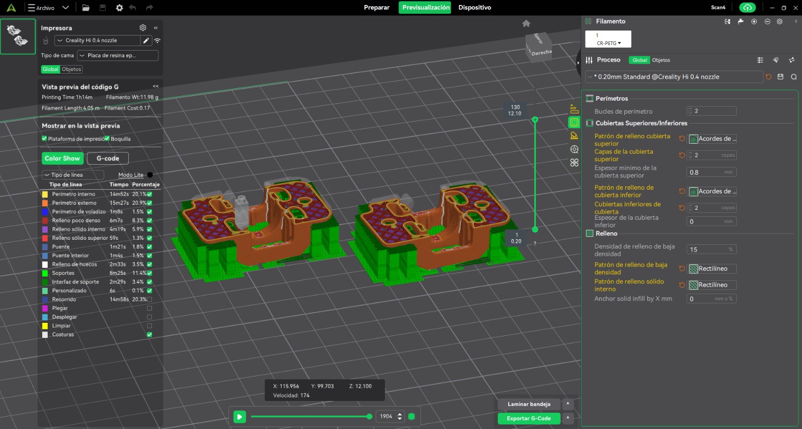
And, as a final step print the previously designed parts using a 3D printer.
Assembly
One of the pieces that we will use will be manufactured using a surface finishing technique with a milling machine in order to remove notches, burrs, and localized ridges that may affect the flatness of the piece. Another type of material can also be used to manufacture this piece using the previous designs.
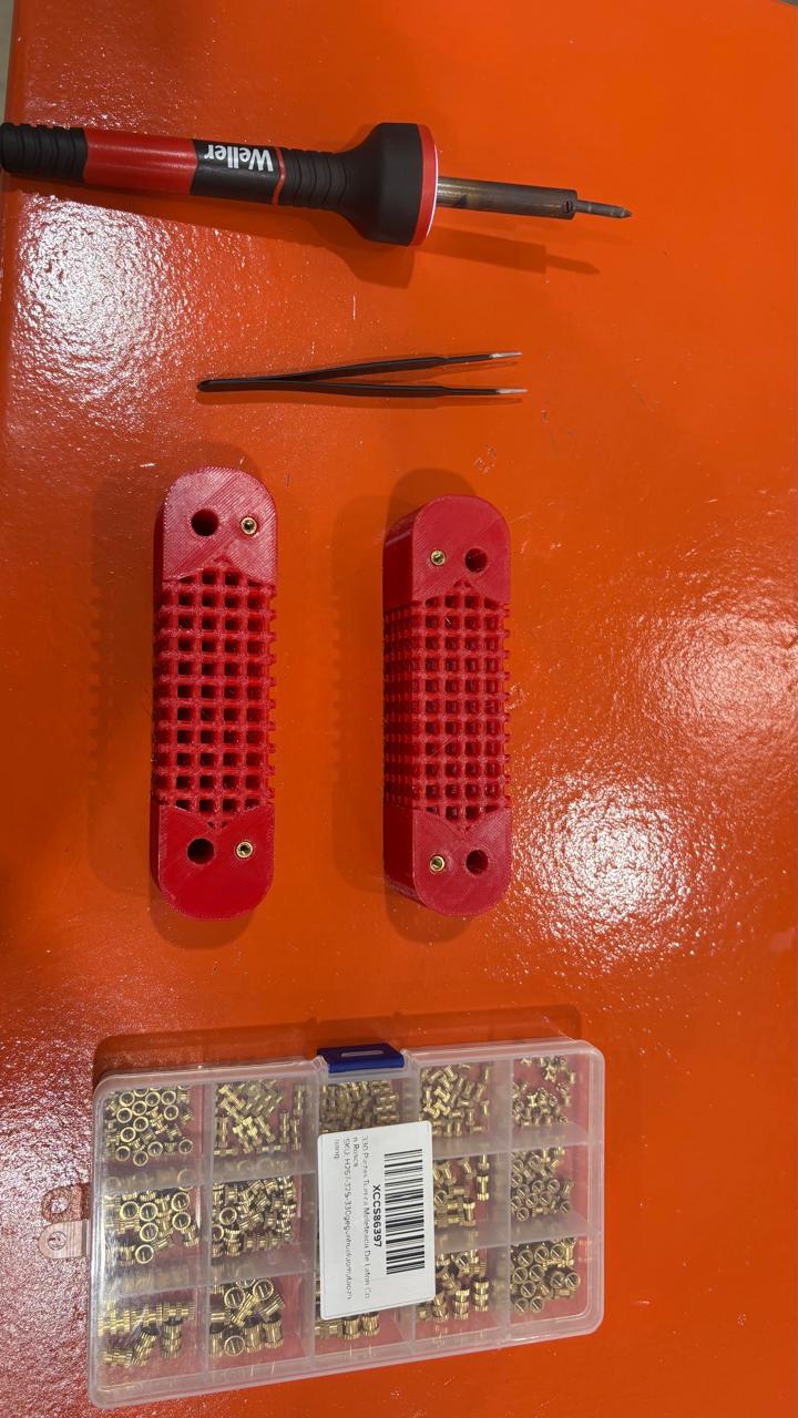
For parts manufactured using 3D printing, brass threaded inserts are used.
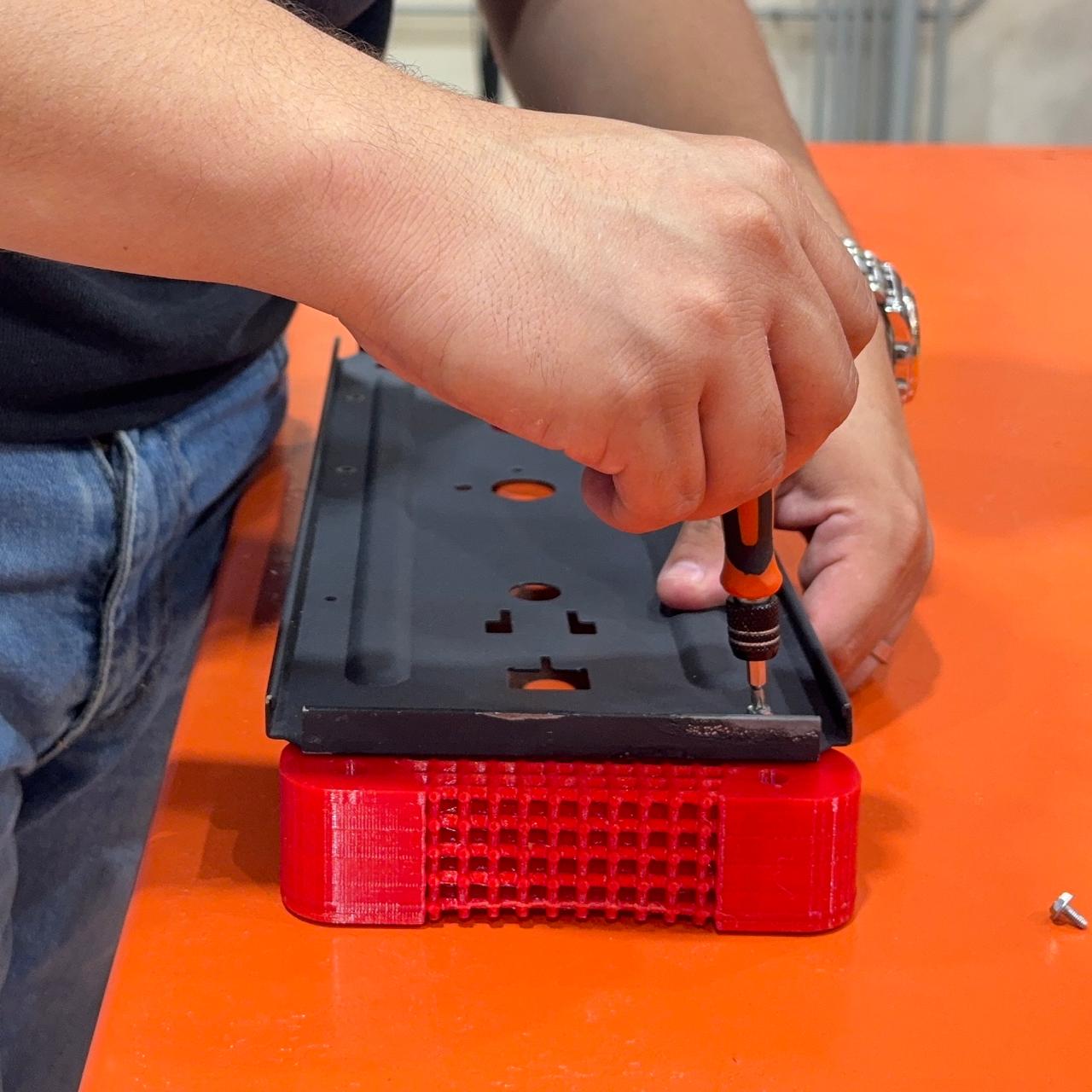
Righty-tighty, lefty-loosey.
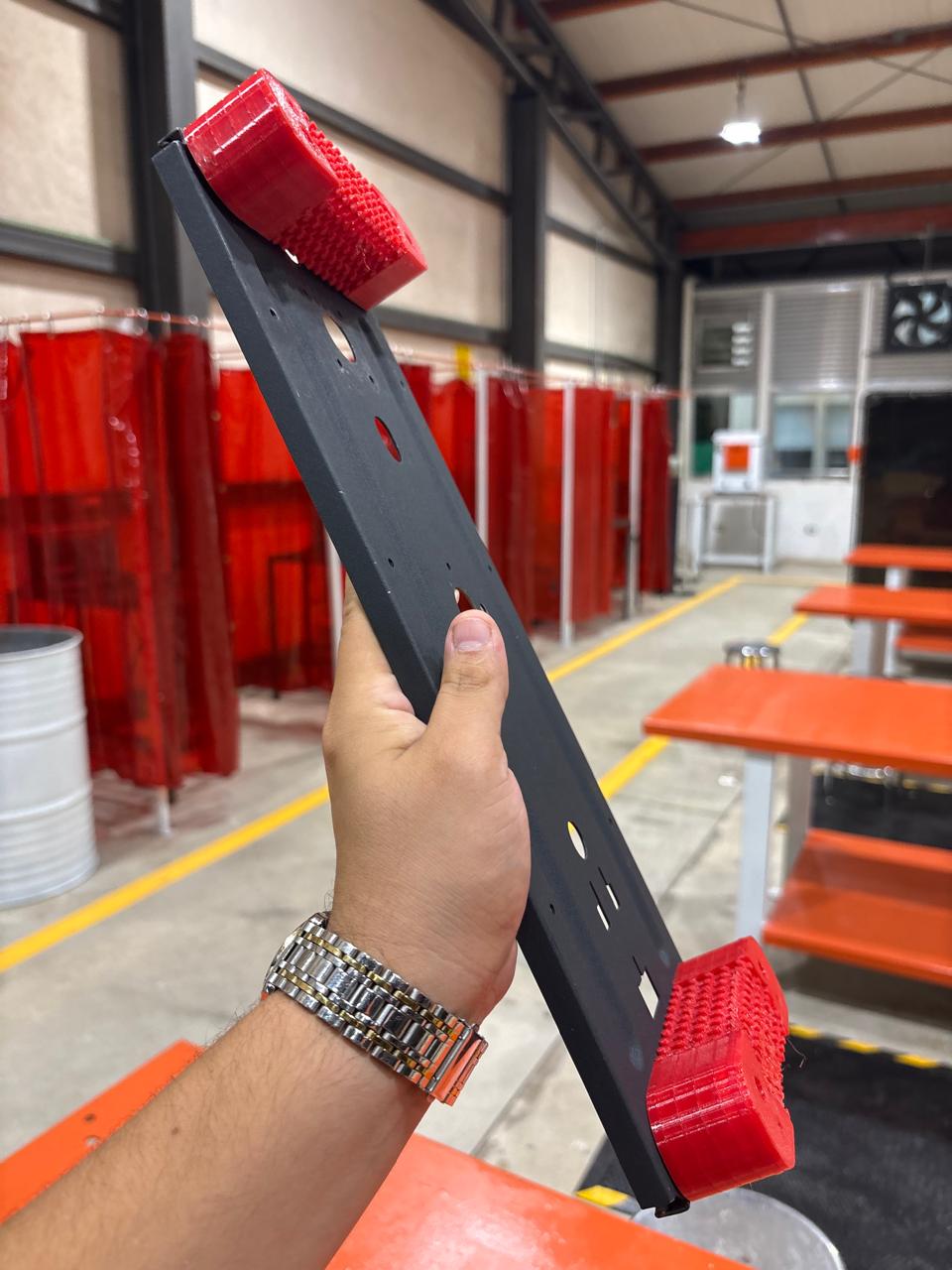
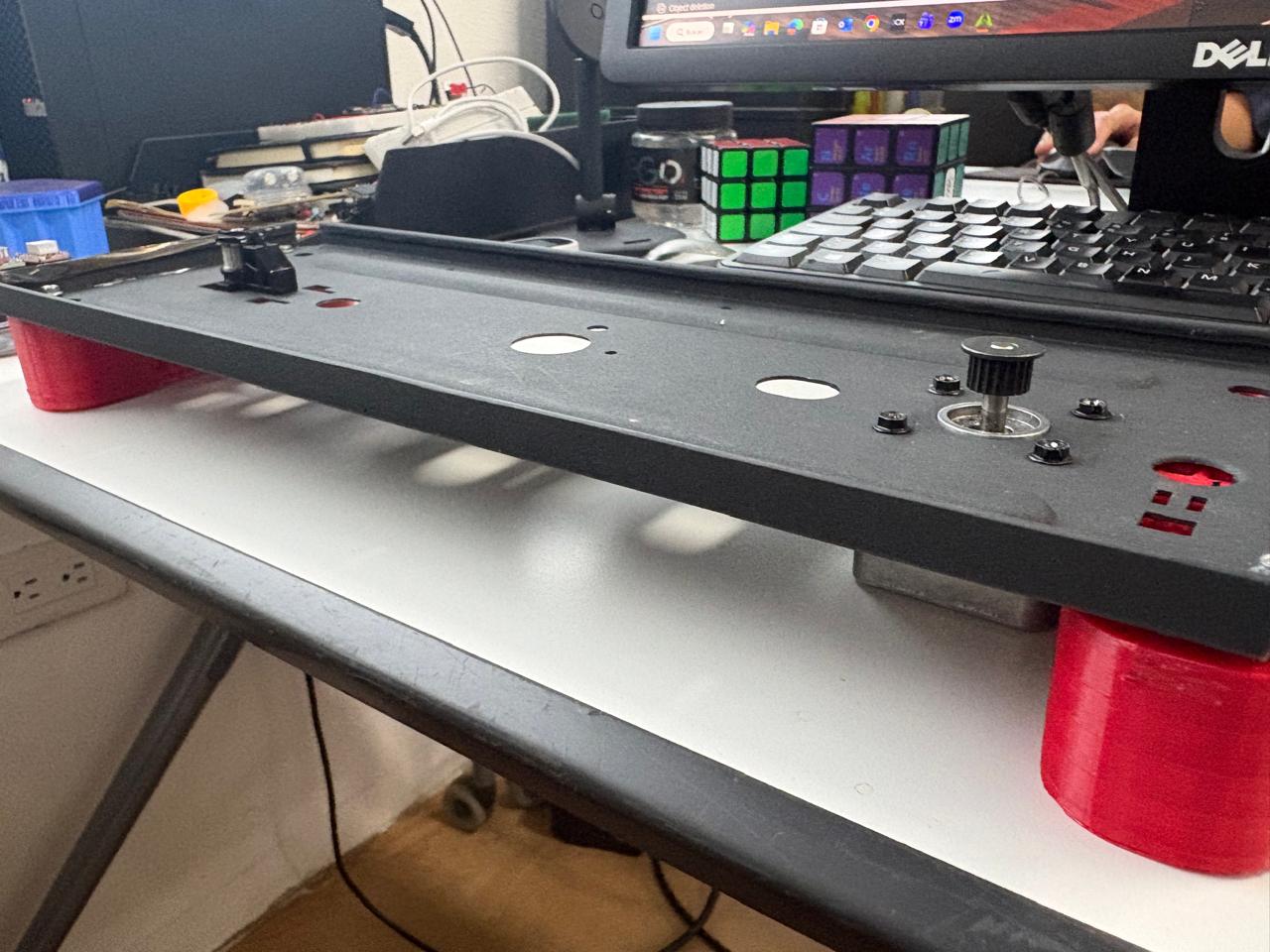
Multiple tolerance, scale, and thickness tests.
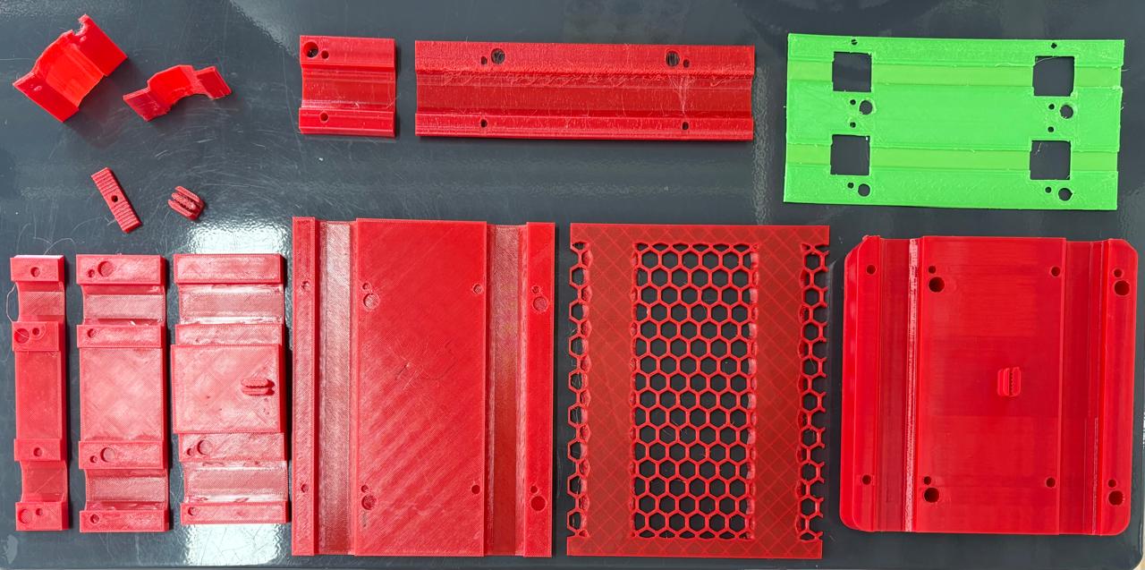
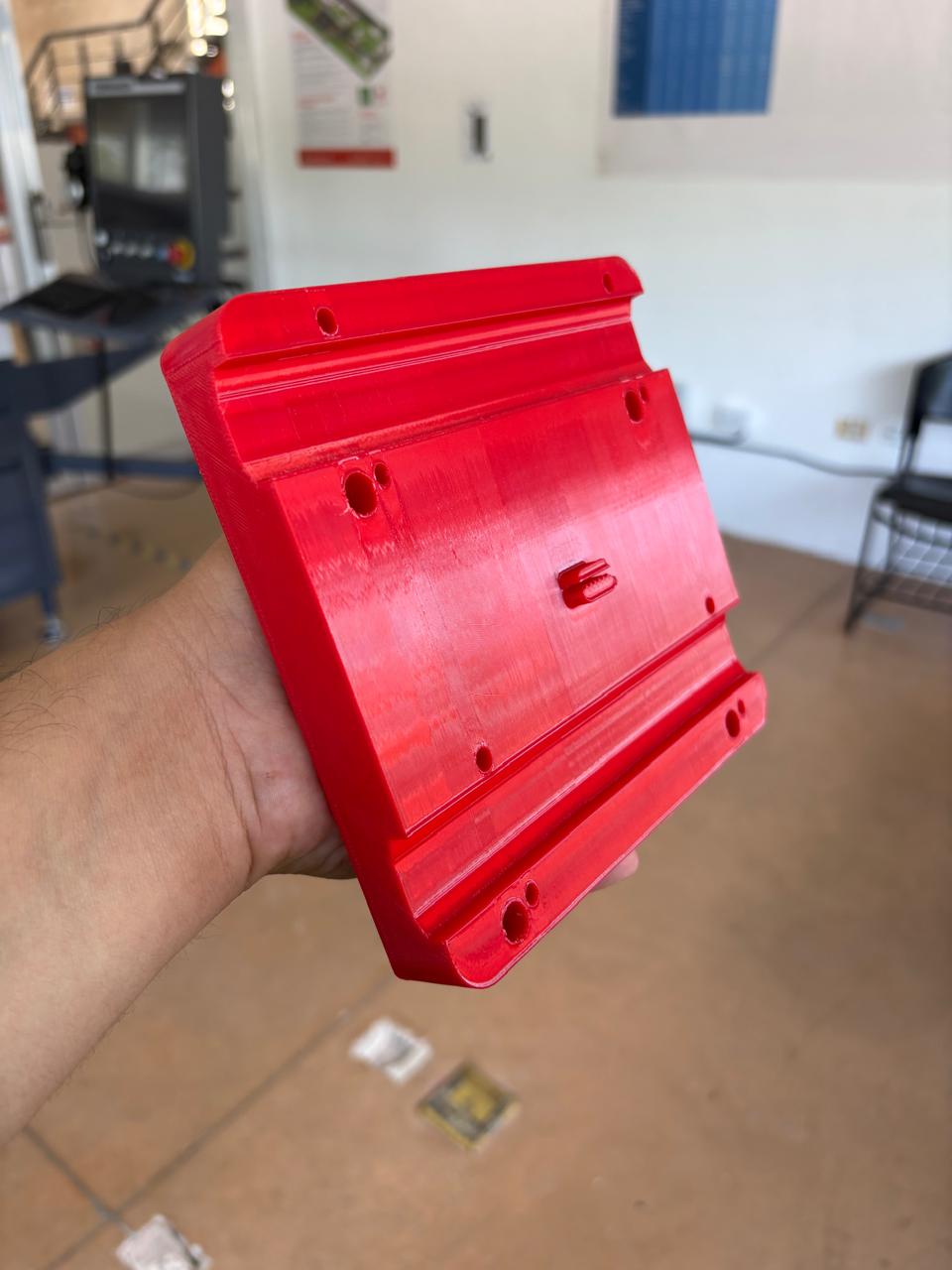
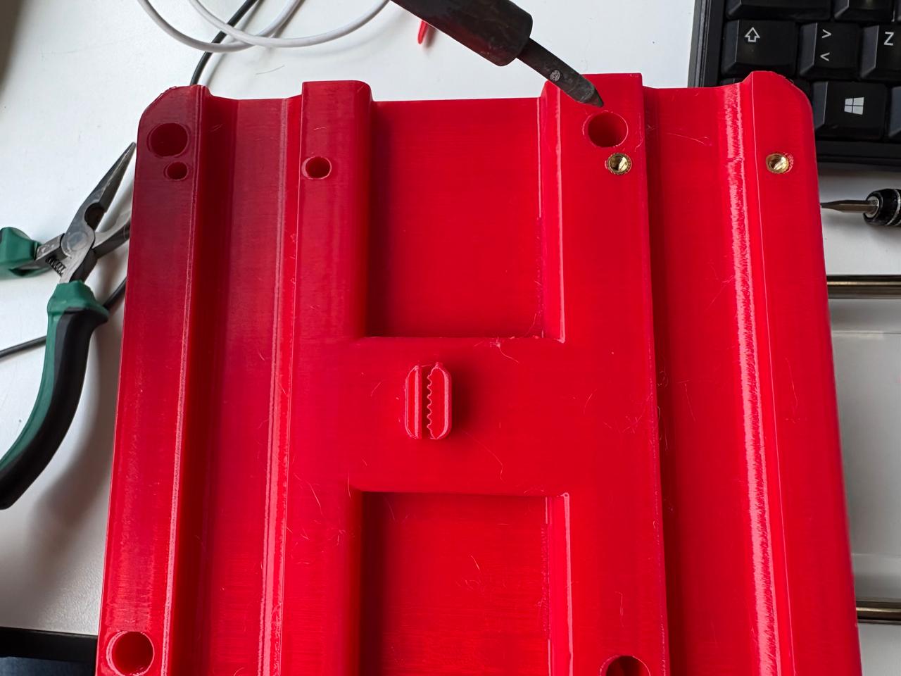
If you think you're stressed, just look at how many screws it takes to hold my sanity together.
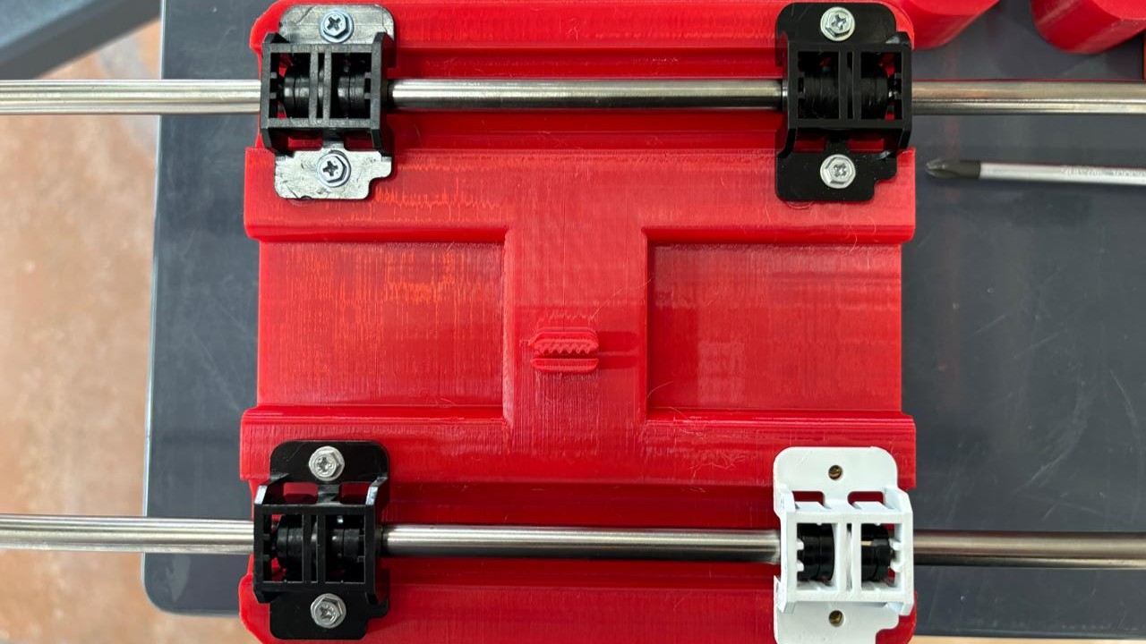
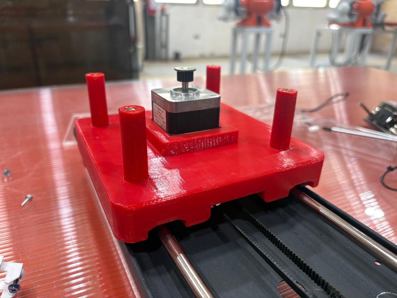
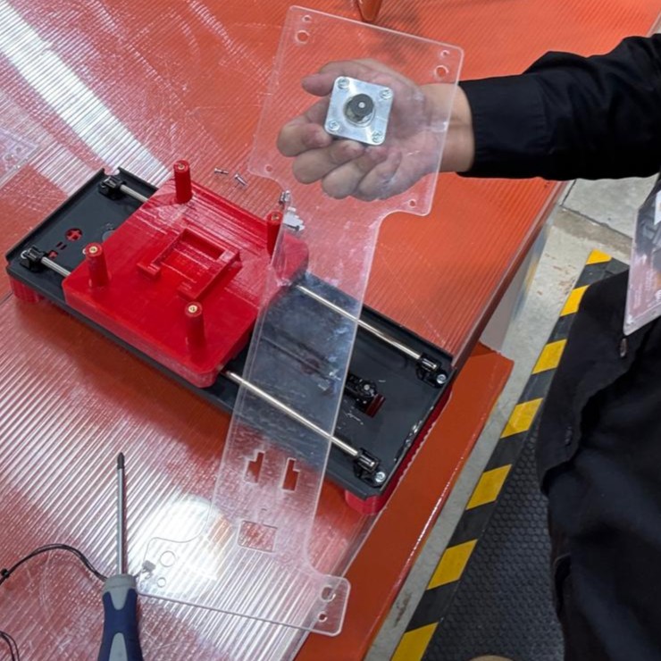
Just tightening a few screws so I don't lose my own.
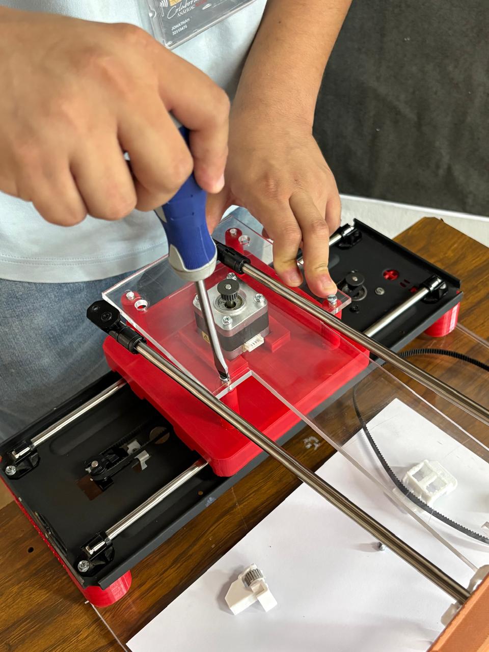
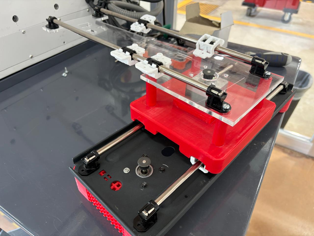
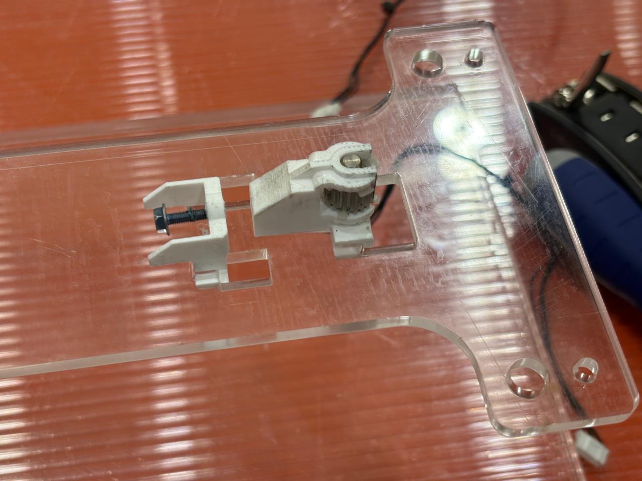
Finally, the icing on the cake.
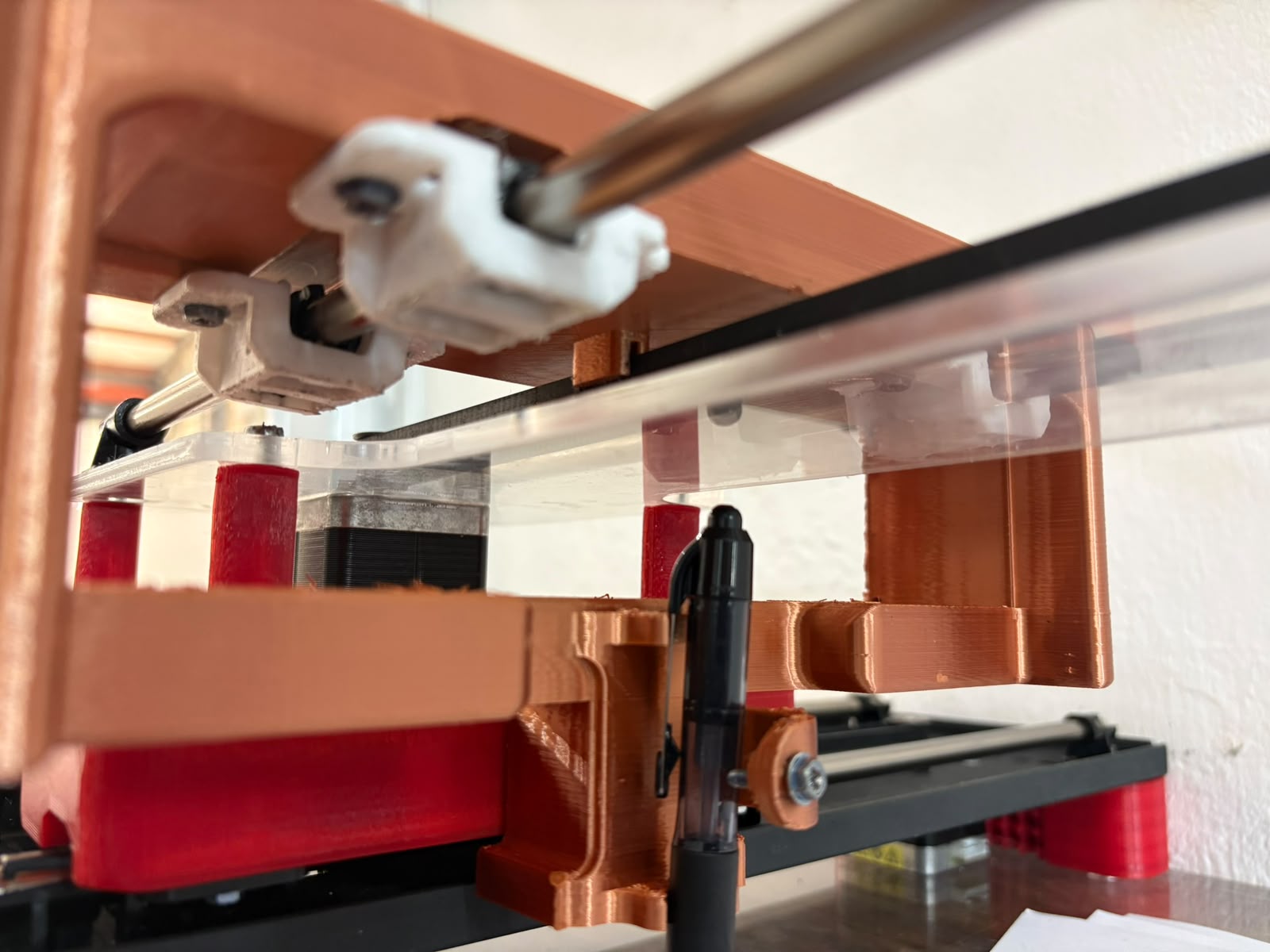
In my case, I had to change the order of some motor cables because some commercial cables use a different arrangement for the coils or motor phases, while the CNC Shield and the driver require a specific sequence to connect them correctly.
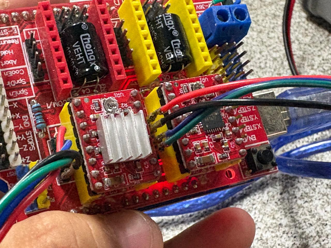
Use the recommended current for the type of motor you are using, as this value is important for calibrating the drivers.
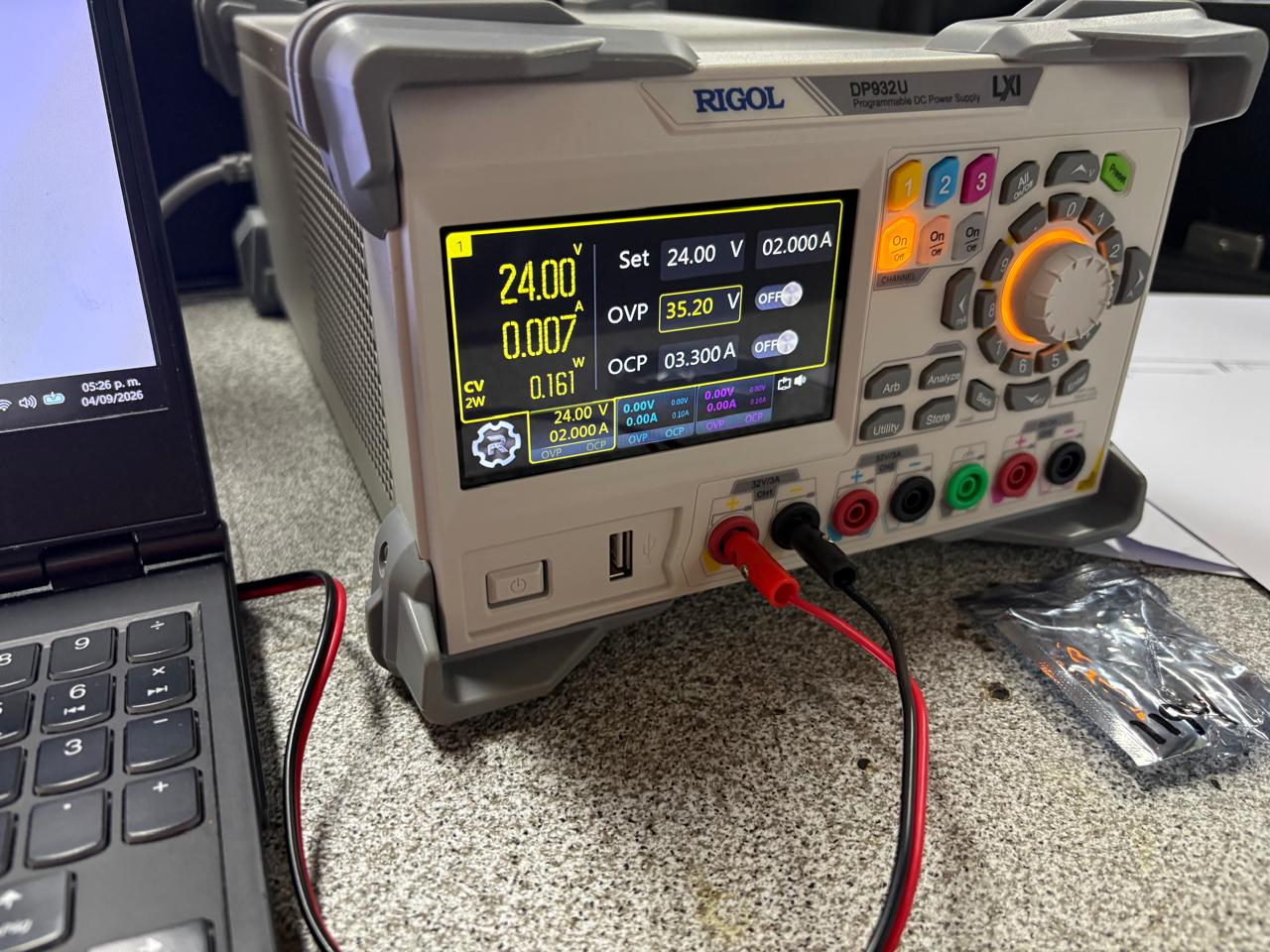
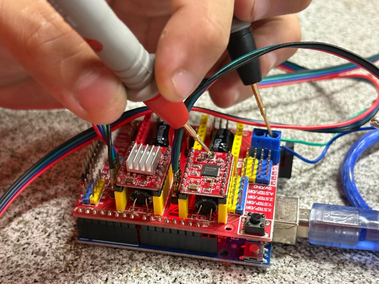
Use a multimeter to measure the Vref of the driver and adjust it according to the current required by the motor.
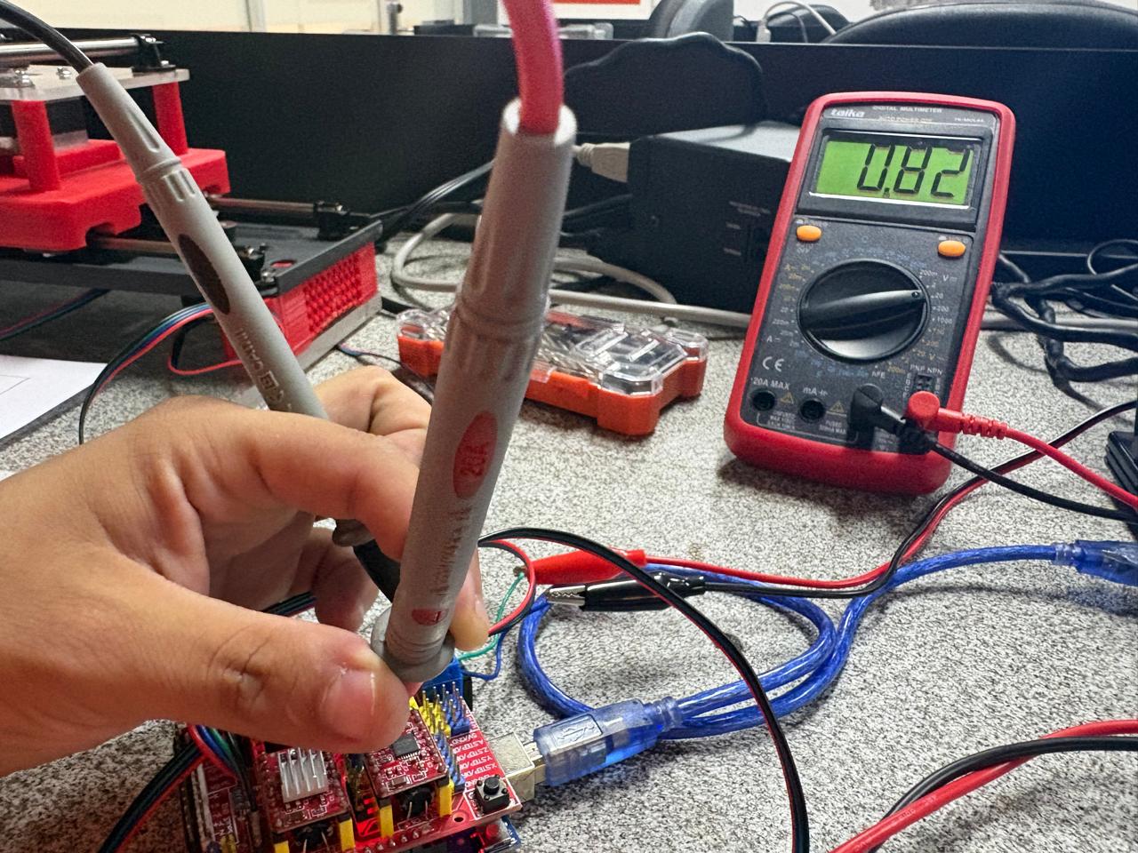
And finally, the most important part is programming both motors.
#define EN_PIN   8
#define X_STEP  2
#define X_DIR   5
#define Y_STEP  3
#define Y_DIR   6

const float stepsPerMm = 80.0;
const int pulseDelayUs = 1500;

float currentX = 0.0;
float currentY = 0.0;

void setup() {
  pinMode(EN_PIN, OUTPUT);
  pinMode(X_STEP, OUTPUT);
  pinMode(X_DIR, OUTPUT);
  pinMode(Y_STEP, OUTPUT);
  pinMode(Y_DIR, OUTPUT);

  digitalWrite(EN_PIN, LOW);
  delay(2000);
}

void loop() {
  digitalWrite(EN_PIN, HIGH);
  delay(1000);
}

void moveTo(float targetX, float targetY) {

  targetX = constrain(targetX, 0.0, 11.0);
  targetY = constrain(targetY, -7.0, 0.0);

  float deltaX = targetX - currentX;
  float deltaY = targetY - currentY;

  if (deltaX > 0) {
    digitalWrite(X_DIR, LOW);
  } else {
    digitalWrite(X_DIR, HIGH);
  }

  if (deltaY < 0) {
    digitalWrite(Y_DIR, HIGH);
  } else {
    digitalWrite(Y_DIR, LOW);
  }

  long stepsX = abs(deltaX * stepsPerMm);
  long stepsY = abs(deltaY * stepsPerMm);

  long maxSteps = max(stepsX, stepsY);

  if (maxSteps == 0) return;

  float ratioX = (float)stepsX / maxSteps;
  float ratioY = (float)stepsY / maxSteps;

  float accumulatorX = 0;
  float accumulatorY = 0;

  for (long i = 0;
       i < maxSteps;
       i++) {

    accumulatorX += ratioX;
    accumulatorY += ratioY;

    if (accumulatorX >= 1.0) {
      digitalWrite(X_STEP, HIGH);
      accumulatorX -= 1.0;
    }

    if (accumulatorY >= 1.0) {
      digitalWrite(Y_STEP, HIGH);
      accumulatorY -= 1.0;
    }

    delayMicroseconds(pulseDelayUs);

    digitalWrite(X_STEP, LOW);
    digitalWrite(Y_STEP, LOW);

    delayMicroseconds(pulseDelayUs);
  }

  currentX = targetX;
  currentY = targetY;
}
X-axis motor test
Y-axis motor test
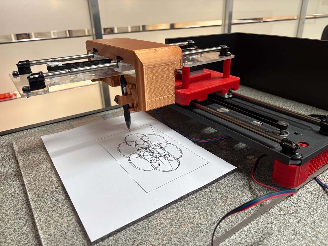
The moment of truth... Turn it on, Otto!
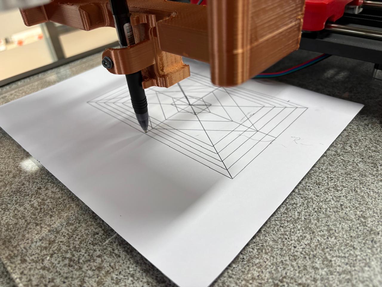
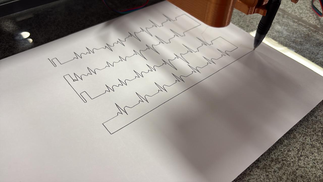
Due to my professional background, I wanted to give the pen plotter a more specific application by adapting it to trace heart rate signals.