Output Devices
Tools
Signal Monitor Developer
Custom Board
Workflow
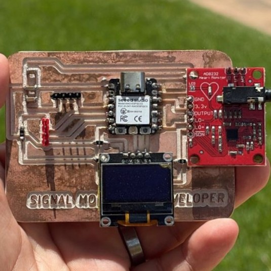
For this assignment, I used the board I developed during the Input Devices week. This board was originally designed to acquire an ECG signal, since it has the analog input connection needed to read the signal coming from the ECG module. In the previous stage, the main goal was to acquire the signal, apply digital signal conditioning, and visualize its behavior using the Serial Plotter. However, for this assignment, I focused on adding an output device to the same system by integrating an OLED display.
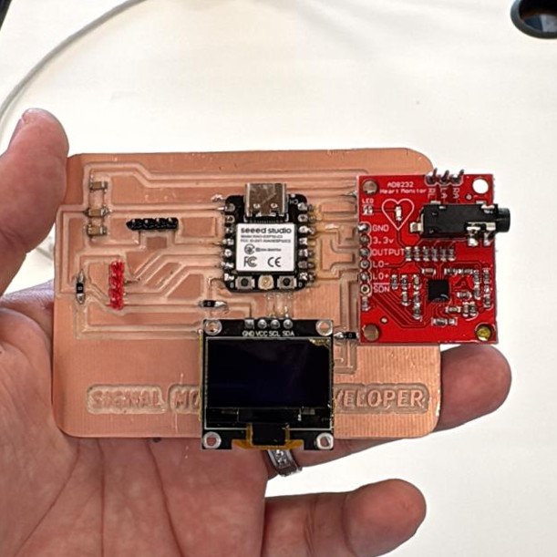
The OLED display was connected using the I2C communication pins available on the board. This is important because the I2C protocol only requires two communication lines, SDA and SCL. This allows for a cleaner connection without using too many microcontroller pins. It also makes the system more scalable, since the same board can continue acquiring the ECG signal while keeping the possibility of adding other output devices or future modules through the I2C bus.
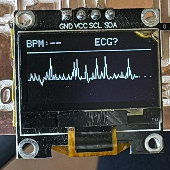
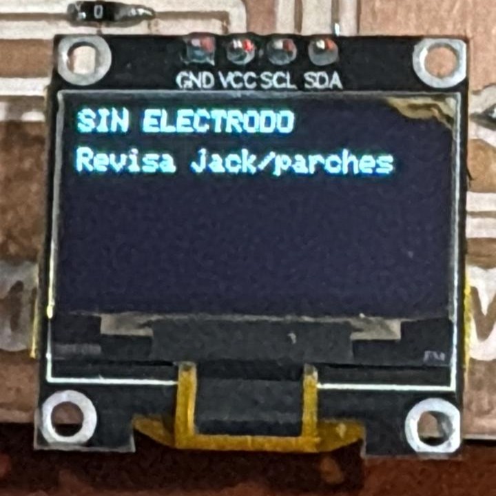
At this stage, the OLED display was used to test the visual interface of the ECG system. The code does not display the real ECG signal on the screen yet. Instead, it generates different test screens to validate the interface design before connecting it to the real signal processing code. The OLED interface includes screens for the ECG signal, raw signal, filtered signal, signal conditioning flow, BPM display, and an initial ready/status screen.
These screens change automatically every five seconds, which allowed me to test how the information could be organized and displayed to the user. This step was useful because it allowed me to separate the visual design from the signal acquisition process. First, I verified that the OLED display worked correctly with the board and that the layout was readable. Then, I designed a visual structure that represents the different stages of the ECG system: raw input, baseline removal, digital filtering, and final output on the display.
#include <Arduino.h>
#include <Wire.h>
#include <Adafruit_GFX.h>
#include <Adafruit_SSD1306.h>
#include <math.h>

#define OLED_WIDTH 128
#define OLED_HEIGHT 64
#define OLED_RESET_PIN -1
#define OLED_I2C_ADDRESS 0x3C

Adafruit_SSD1306 oledDisplay(OLED_WIDTH, OLED_HEIGHT, &Wire, OLED_RESET_PIN);

const unsigned long screenChangeIntervalMs = 5000;
const unsigned long animationRefreshIntervalMs = 80;
const int totalScreenDesigns = 6;

int currentScreenDesign = 0;
unsigned long lastScreenChangeMs = 0;
unsigned long lastAnimationRefreshMs = 0;
int animationFrame = 0;

const int ecgBaselineY = 42;
const int ecgWaveAmplitude = 7;
const int ecgPeakHeight = 18;
const int ecgAnimationSpeed = 4;

void drawCenteredText(String text, int yPosition, int textSize) {
  oledDisplay.setTextSize(textSize);
  oledDisplay.setTextColor(SSD1306_WHITE);

  int16_t textX, textY;
  uint16_t textWidth, textHeight;

  oledDisplay.getTextBounds(text, 0, yPosition, &textX, &textY, &textWidth, &textHeight);

  int centeredX = (OLED_WIDTH - textWidth) / 2;
  oledDisplay.setCursor(centeredX, yPosition);
  oledDisplay.print(text);
}

void drawTopStatusBar(String title) {
  oledDisplay.fillRect(0, 0, OLED_WIDTH, 12, SSD1306_WHITE);

  oledDisplay.setTextColor(SSD1306_BLACK);
  oledDisplay.setTextSize(1);
  oledDisplay.setCursor(3, 2);
  oledDisplay.print(title);

  // Battery icon
  oledDisplay.drawRect(108, 3, 15, 7, SSD1306_BLACK);
  oledDisplay.fillRect(123, 5, 2, 3, SSD1306_BLACK);
  oledDisplay.fillRect(110, 5, 10, 3, SSD1306_BLACK);

  oledDisplay.setTextColor(SSD1306_WHITE);
}

void drawHeartIcon(int centerX, int centerY) {
  oledDisplay.fillCircle(centerX - 3, centerY, 4, SSD1306_WHITE);
  oledDisplay.fillCircle(centerX + 3, centerY, 4, SSD1306_WHITE);
  oledDisplay.fillTriangle(centerX - 7, centerY + 2, centerX + 7, centerY + 2, centerX, centerY + 11, SSD1306_WHITE);
}

void drawReferenceLine(int yPosition) {
  for (int xPosition = 0; xPosition < OLED_WIDTH; xPosition += 4) {
    oledDisplay.drawPixel(xPosition, yPosition, SSD1306_WHITE);
  }
}

void drawEcgWavePreview(int baselineY, int phaseOffset) {
  for (int xPosition = 0; xPosition < OLED_WIDTH - 1; xPosition++) {
    float mainWave = sin((xPosition + phaseOffset) * 0.18) * ecgWaveAmplitude;
    float smallVariation = sin((xPosition + phaseOffset) * 0.055) * 3;

    int currentY = baselineY + mainWave + smallVariation;

    int nextY = baselineY +
                sin((xPosition + 1 + phaseOffset) * 0.18) * ecgWaveAmplitude +
                sin((xPosition + 1 + phaseOffset) * 0.055) * 3;

    // QRS-style peak used only for OLED interface testing
    if ((xPosition + phaseOffset) % 42 == 0) {
      currentY = baselineY - ecgPeakHeight;
    }

    oledDisplay.drawLine(xPosition, currentY, xPosition + 1, nextY, SSD1306_WHITE);
  }
}

void showStartupScreen() {
  oledDisplay.clearDisplay();

  drawHeartIcon(64, 18);

  drawCenteredText("ECG SIGNAL", 34, 1);
  drawCenteredText("INTERFACE", 46, 2);

  oledDisplay.drawRoundRect(18, 58, 92, 5, 2, SSD1306_WHITE);

  int loadingBarWidth = map(animationFrame % 40, 0, 39, 0, 88);
  oledDisplay.fillRoundRect(20, 59, loadingBarWidth, 3, 1, SSD1306_WHITE);

  oledDisplay.display();
}

void showRawSignalScreen() {
  oledDisplay.clearDisplay();

  drawTopStatusBar("RAW ECG SIGNAL");

  oledDisplay.setTextSize(1);
  oledDisplay.setCursor(4, 17);
  oledDisplay.print("ADC");

  oledDisplay.setTextSize(2);
  oledDisplay.setCursor(4, 31);
  oledDisplay.print("---");

  oledDisplay.setTextSize(1);
  oledDisplay.setCursor(55, 18);
  oledDisplay.print("INPUT");

  oledDisplay.drawRoundRect(54, 29, 68, 25, 4, SSD1306_WHITE);
  drawEcgWavePreview(ecgBaselineY, animationFrame * ecgAnimationSpeed);

  oledDisplay.setCursor(65, 56);
  oledDisplay.print("RAW DATA");

  oledDisplay.display();
}

void showFilteredSignalScreen() {
  oledDisplay.clearDisplay();

  drawTopStatusBar("FILTERED ECG");

  oledDisplay.setTextSize(1);
  oledDisplay.setCursor(5, 17);
  oledDisplay.print("BASELINE");

  drawReferenceLine(39);
  drawEcgWavePreview(39, animationFrame * ecgAnimationSpeed);

  oledDisplay.drawRoundRect(8, 52, 112, 9, 3, SSD1306_WHITE);
  oledDisplay.setCursor(22, 54);
  oledDisplay.print("SMOOTHED SIGNAL");

  oledDisplay.display();
}

void showConditioningFlowScreen() {
  oledDisplay.clearDisplay();

  drawTopStatusBar("CONDITIONING");

  oledDisplay.setTextSize(1);

  oledDisplay.setCursor(8, 18);
  oledDisplay.print("RAW INPUT");

  oledDisplay.setCursor(8, 30);
  oledDisplay.print("BASELINE REMOVAL");

  oledDisplay.setCursor(8, 42);
  oledDisplay.print("DIGITAL FILTER");

  oledDisplay.setCursor(8, 54);
  oledDisplay.print("OLED OUTPUT");

  oledDisplay.drawCircle(112, 36, 10, SSD1306_WHITE);
  oledDisplay.drawLine(106, 36, 111, 42, SSD1306_WHITE);
  oledDisplay.drawLine(111, 42, 119, 29, SSD1306_WHITE);

  oledDisplay.display();
}

void showHeartRateScreen() {
  oledDisplay.clearDisplay();

  drawTopStatusBar("ECG MONITOR");

  oledDisplay.setTextSize(1);
  oledDisplay.setCursor(4, 17);
  oledDisplay.print("BPM");

  oledDisplay.setTextSize(3);
  oledDisplay.setCursor(4, 28);
  oledDisplay.print("--");

  oledDisplay.setTextSize(1);
  oledDisplay.setCursor(55, 18);
  oledDisplay.print("ECG");

  oledDisplay.drawRoundRect(54, 29, 68, 25, 4, SSD1306_WHITE);
  drawEcgWavePreview(ecgBaselineY, animationFrame * ecgAnimationSpeed);

  oledDisplay.setCursor(68, 56);
  oledDisplay.print("TEST MODE");

  oledDisplay.display();
}

void showReadyScreen() {
  oledDisplay.clearDisplay();

  oledDisplay.drawRoundRect(5, 5, 118, 54, 8, SSD1306_WHITE);

  drawCenteredText("READY", 14, 2);
  drawCenteredText("OLED ECG UI", 36, 1);
  drawCenteredText("5s SCREEN LOOP", 49, 1);

  oledDisplay.display();
}

void setup() {
  Serial.begin(115200);
  delay(500);

  if (!oledDisplay.begin(SSD1306_SWITCHCAPVCC, OLED_I2C_ADDRESS)) {
    Serial.println("OLED display was not detected");
    while (true);
  }

  oledDisplay.clearDisplay();
  oledDisplay.display();

  lastScreenChangeMs = millis();
}

void loop() {
  unsigned long currentTimeMs = millis();

  // Change OLED screen every 5 seconds
  if (currentTimeMs - lastScreenChangeMs >= screenChangeIntervalMs) {
    lastScreenChangeMs = currentTimeMs;
    currentScreenDesign++;

    if (currentScreenDesign >= totalScreenDesigns) {
      currentScreenDesign = 0;
    }
  }

  // Refresh OLED animation
  if (currentTimeMs - lastAnimationRefreshMs >= animationRefreshIntervalMs) {
    lastAnimationRefreshMs = currentTimeMs;
    animationFrame++;

    switch (currentScreenDesign) {
      case 0:
        showStartupScreen();
        break;

      case 1:
        showRawSignalScreen();
        break;

      case 2:
        showFilteredSignalScreen();
        break;

      case 3:
        showConditioningFlowScreen();
        break;

      case 4:
        showHeartRateScreen();
        break;

      case 5:
        showReadyScreen();
        break;
    }
  }
}
Test
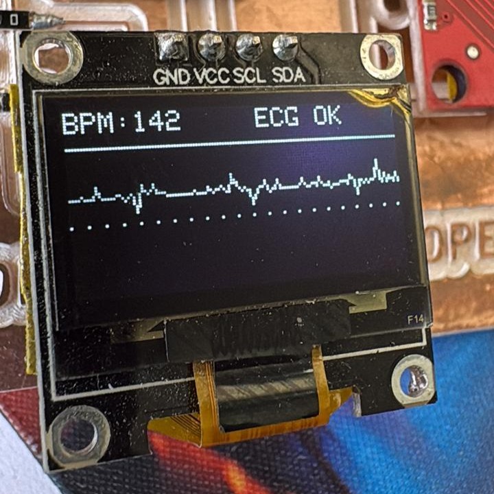
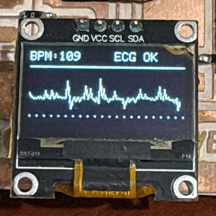
Second, the processed data was sent to an OLED display through I2C communication, allowing real-time visualization of the signal. During testing, the values shown on the OLED did not always match the readings from the Arduino Serial Monitor. Therefore, both the filtering process and the display mapping were adjusted several times until the readings became more stable and consistent.
This project is scalable because the same board can work both as an input system and as an output system. The ECG signal can be acquired through the analog input, processed inside the microcontroller, and later displayed on the OLED screen through I2C. In future iterations, the visual interface can be connected directly to the real ECG processing code, allowing the OLED to show the waveform, BPM estimation, signal status, and feedback from the conditioning process in real time.