ELECTRONIC PRODUCTION
Tools
CNC design - Software and hardware
Used to define cutting operations, tool parameters, and generate G-code for machining.
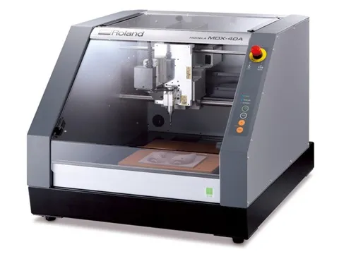
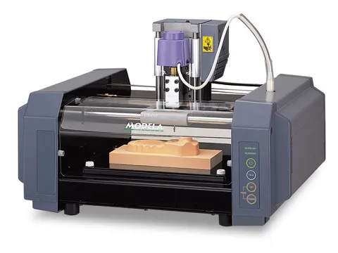
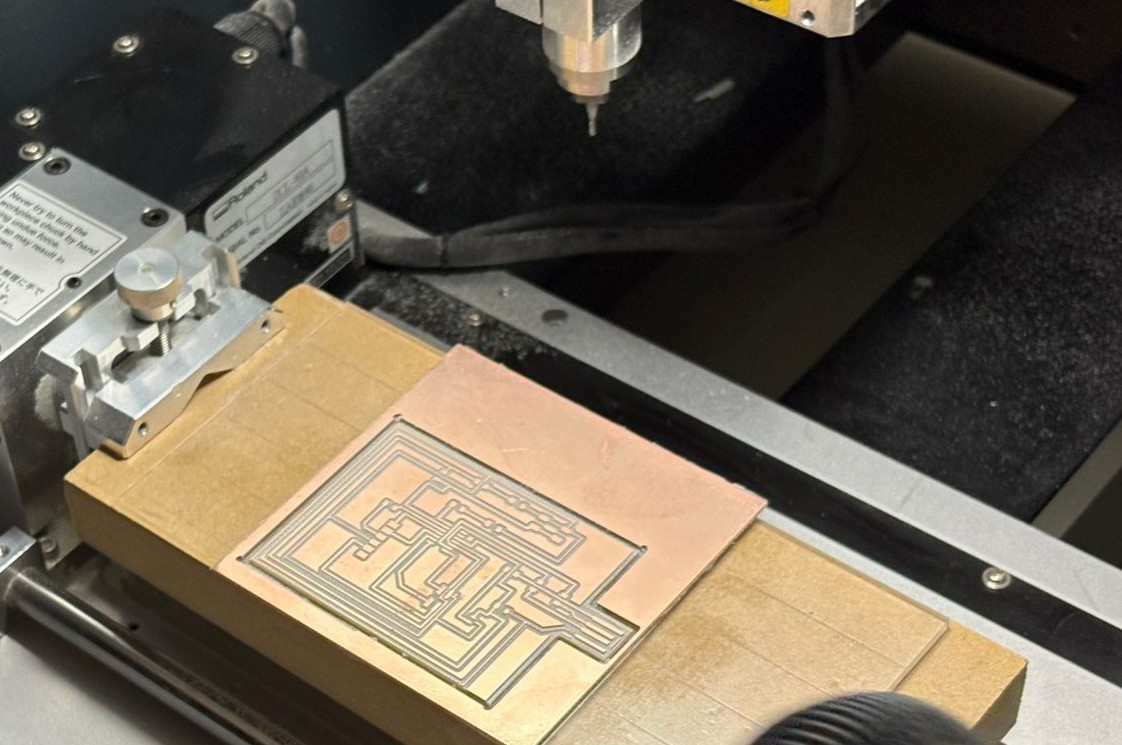
The Roland MDX-20 is a desktop milling machine widely used in PCB production processes. In this case, it was integrated with Mods to generate cutting toolpaths from designs created in KiCad.
|
|
|
|---|---|---|
| Machine Model | Roland MDX-40A | Roland MDX-20 |
| Working Area | ~305 × 305 × 105 mm | ~203 × 152 × 60 mm |
| Axes | 3-axis (X, Y, Z) | 3-axis (X, Y, Z) |
| Spindle Speed | Up to ~15,000 RPM | Up to ~6,500 RPM |
| Materials | Wax, wood, plastic, soft metals | Wax, wood, plastic |
| Typical Use | Molds, prototypes, PCBs | Small prototypes, PCBs |
| Control | Modela Player / Mods | Mods |
Workflow
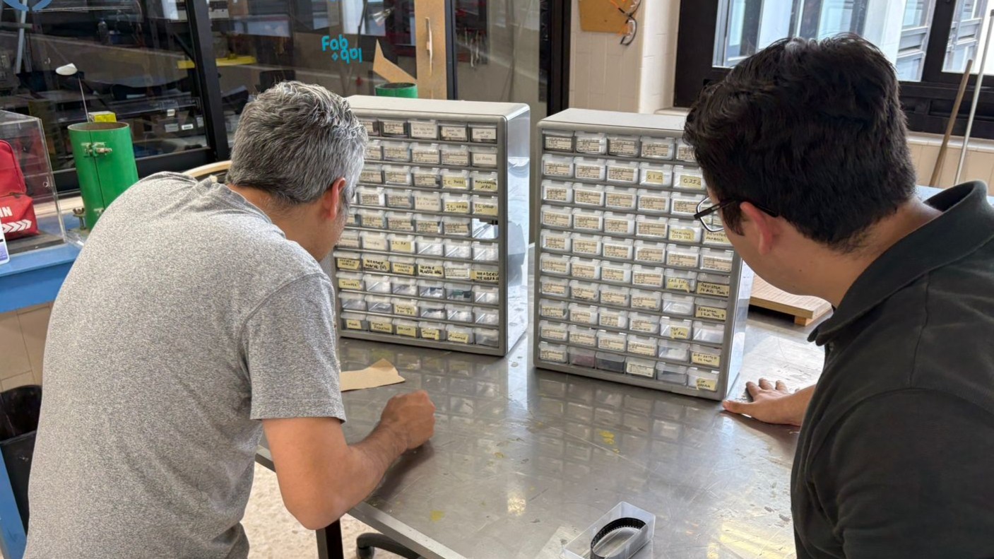
We searched for the materials and components needed for our board previously designed in KiCad.
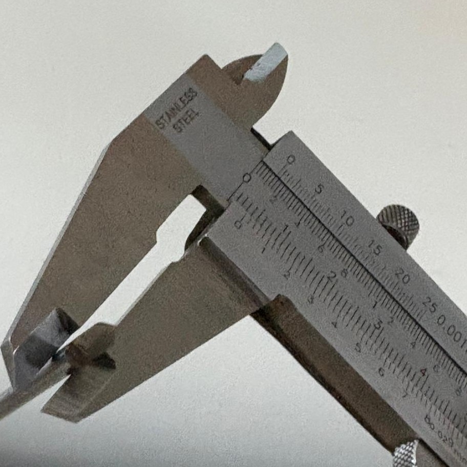
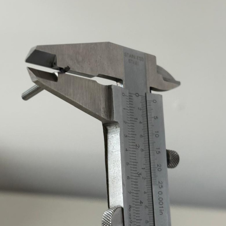
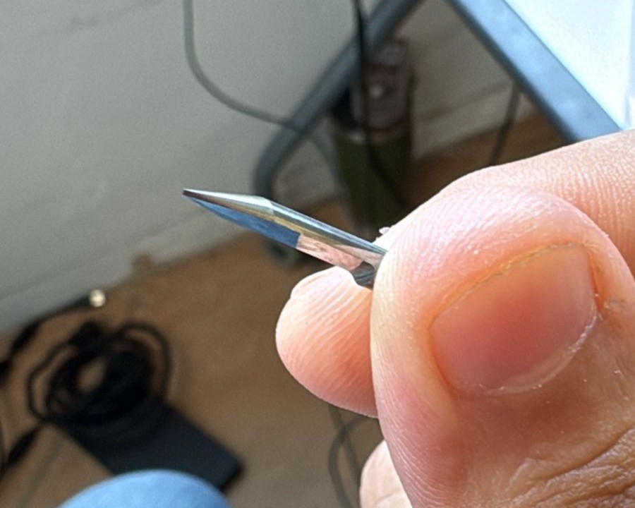
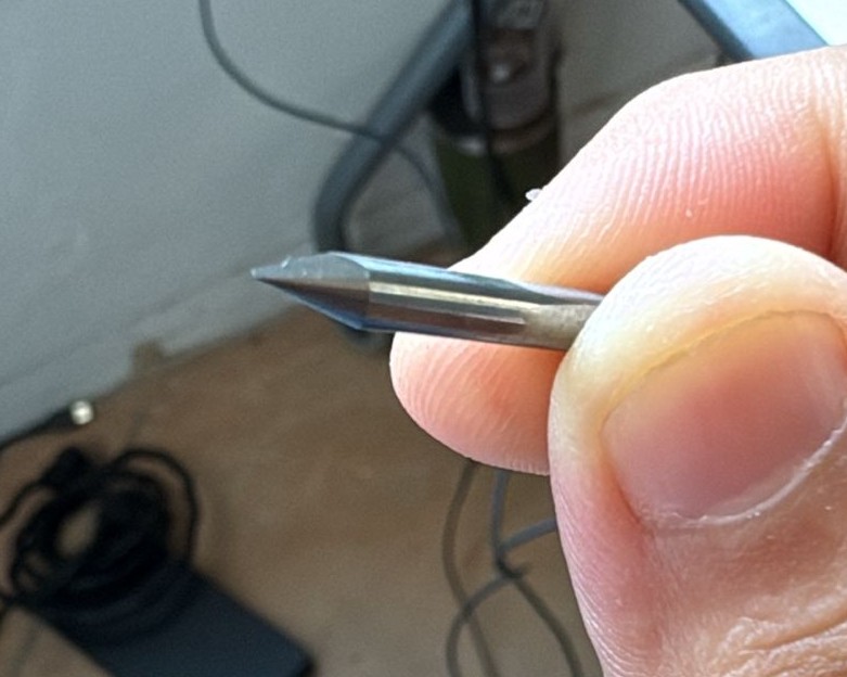
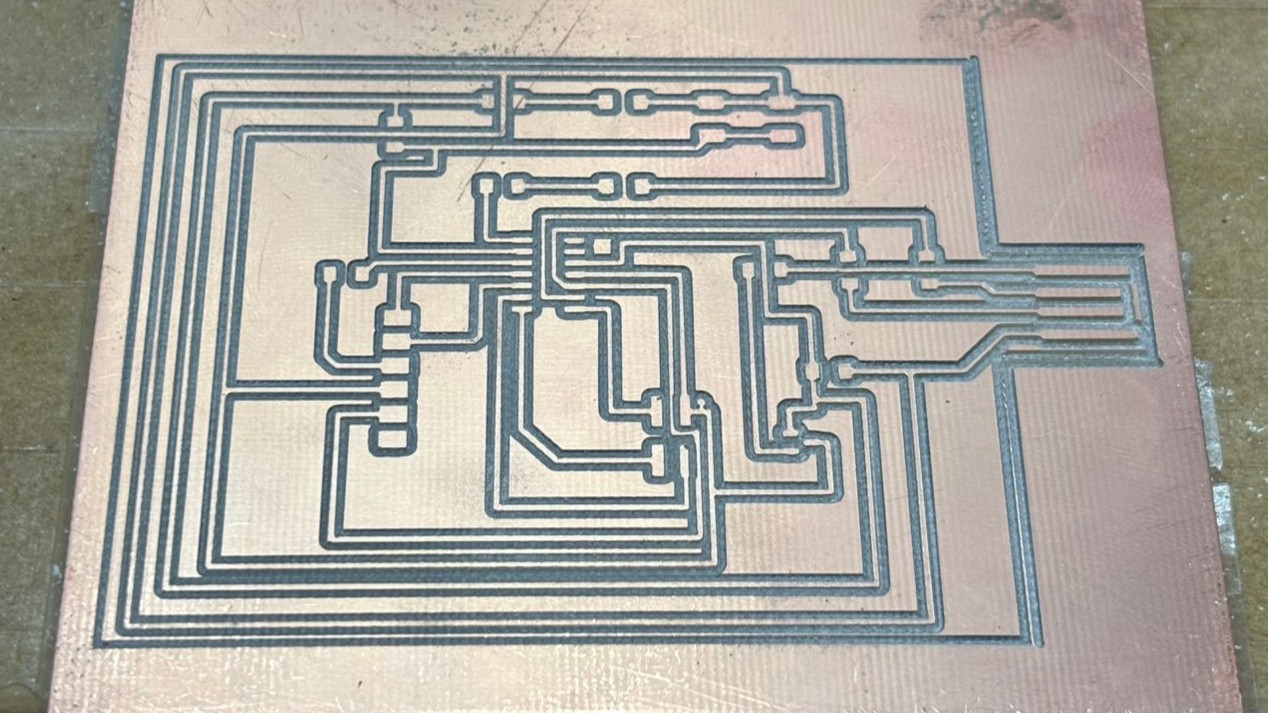
The material thickness was measured to ensure it met the dimensions of the designed traces. In this case, a V-bit was used for the trace milling and a flat end mill was used for cutting the board.
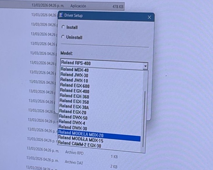
Before starting it’s important to install the drivers for the Roland machines. In our case, we used Windows for communication. However, if you use Linux, you can avoid these steps.
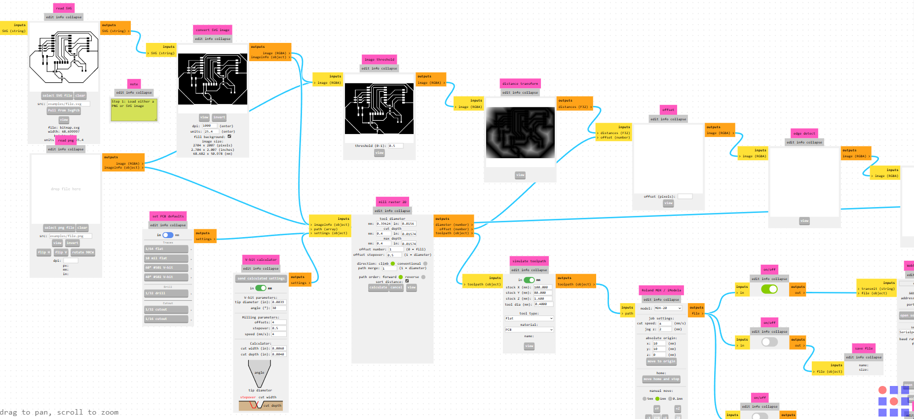
We used MODS to generate the toolpaths and send the machining instructions to the Roland milling machine, allowing us to process the design files and convert them into commands that the machine can interpret.
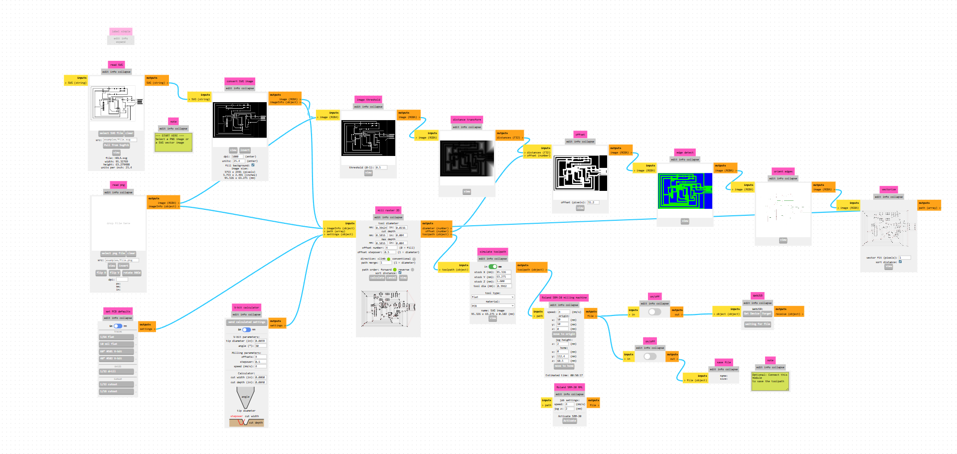
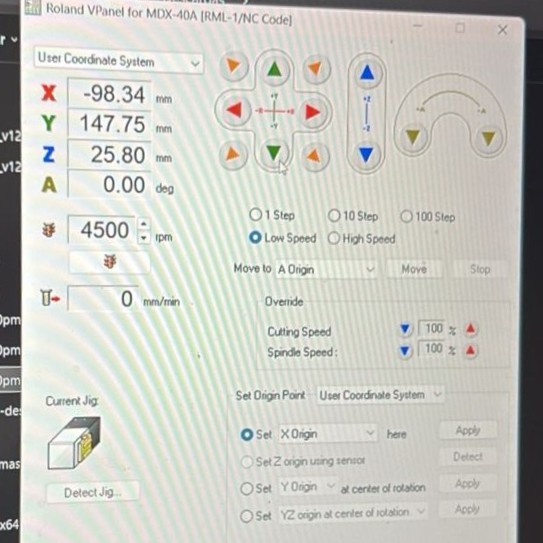
Mods generates an RML file, which is then sent through VPanel to the Roland MDX-40A.
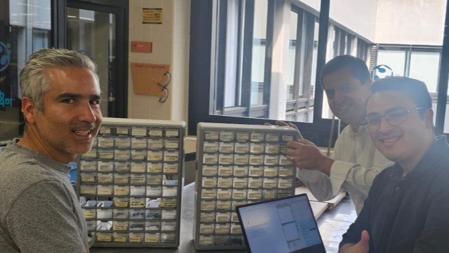
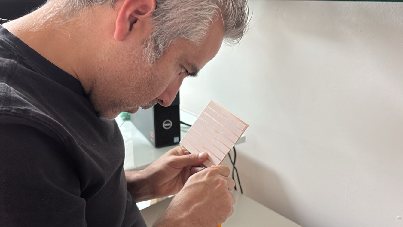
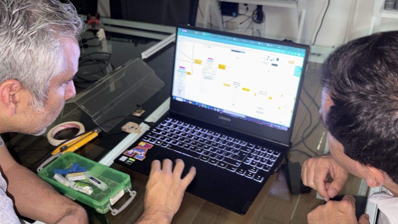
In this photo you can see Rodrigo glad because the file worked correctly
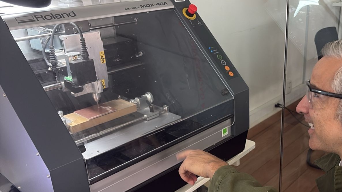
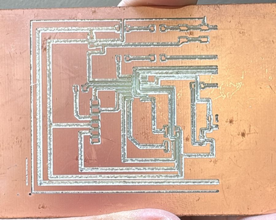
In this case, the tool was changed to an end mill to cut the board, removing material around the contour of the design to separate the final piece from the stock.
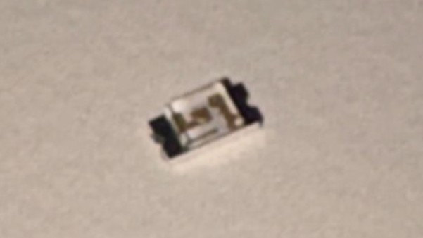
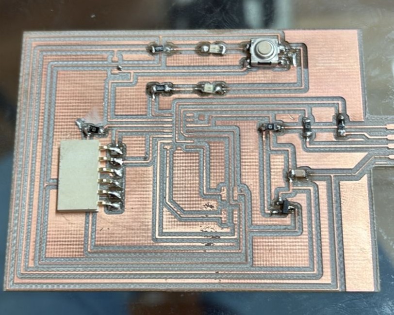
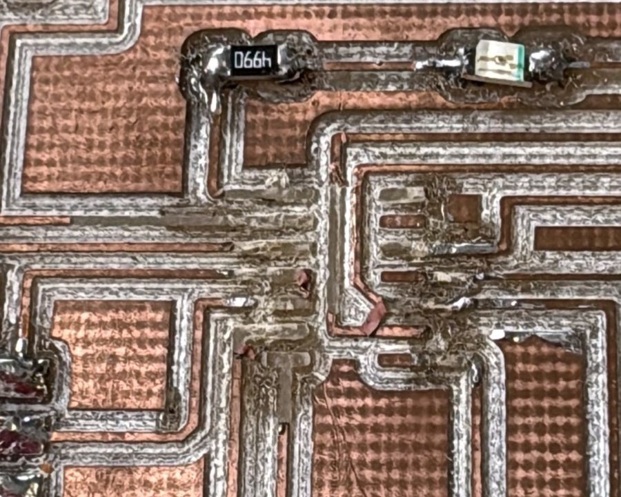
After the cutting process, the surface-mount (SMD) soldering of the components was carried out, including resistors, capacitors, the microcontroller, LEDs, and connectors.
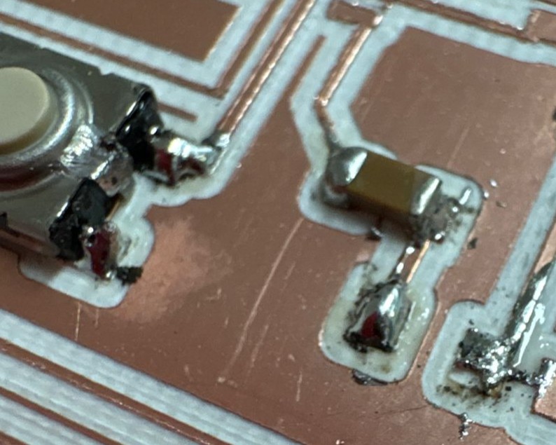
During the process, some issues in solder quality were observed such as excess solder and small accumulations but with patience and practice. All electrical connections were properly completed.
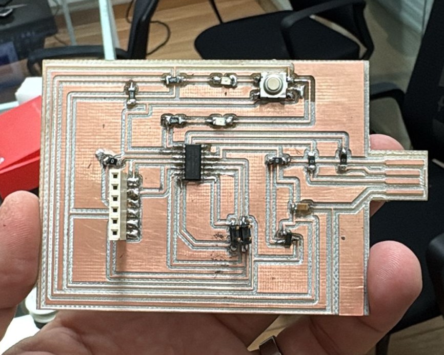
With the workflow established, additional boards were fabricated to validate and test the programming of the microcontrollers.
After soldering all the components, we encountered a serious error. The SAMD microcontroller was placed in the wrong orientation. Because of this, we had to desolder the components, but some of the PCB traces were damaged during the process.
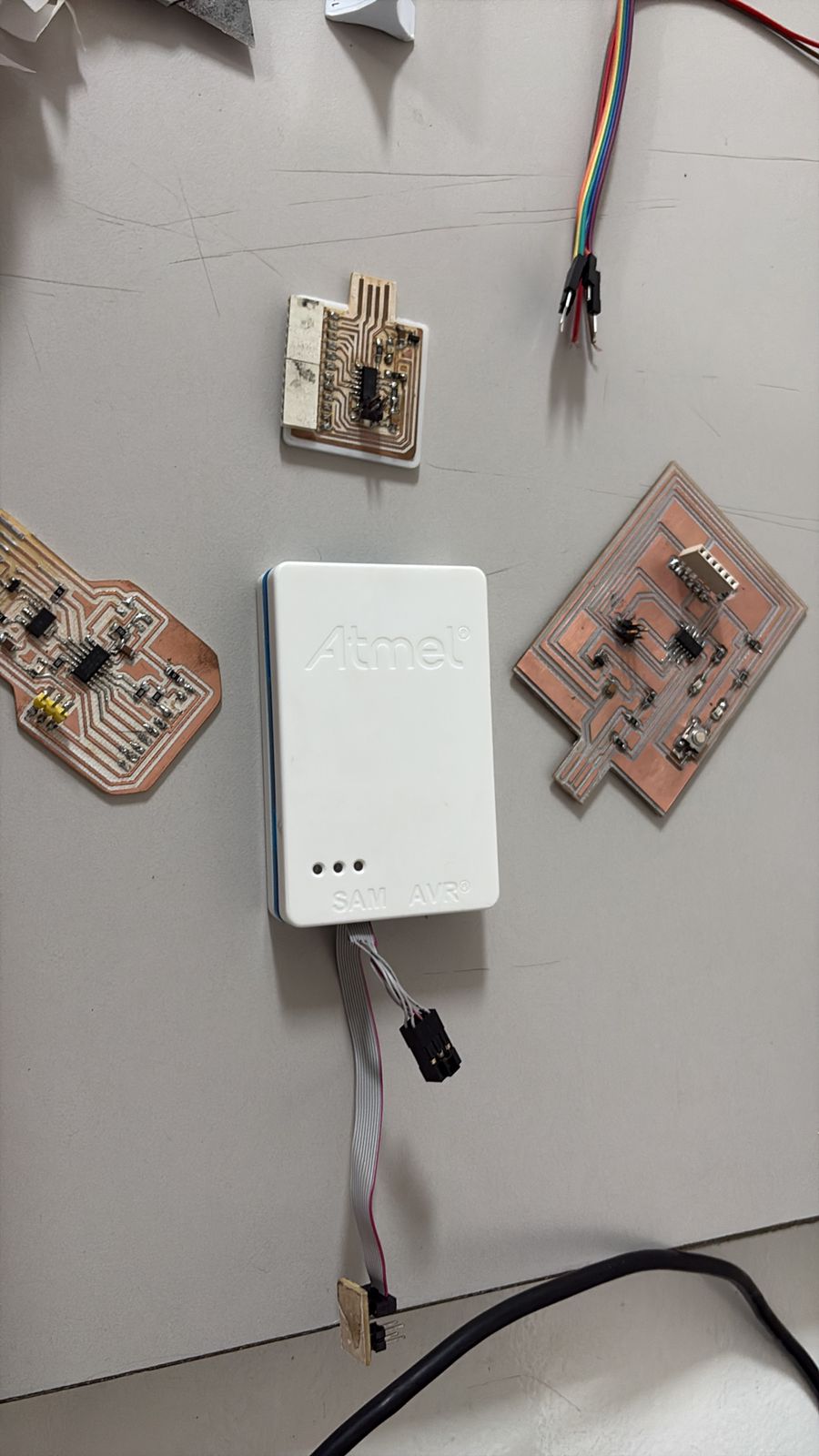
However, at the same time, we were working on another board, which allowed us to avoid losing more time and continue with the workflow. In this case, we continued the project using a XIAO board.
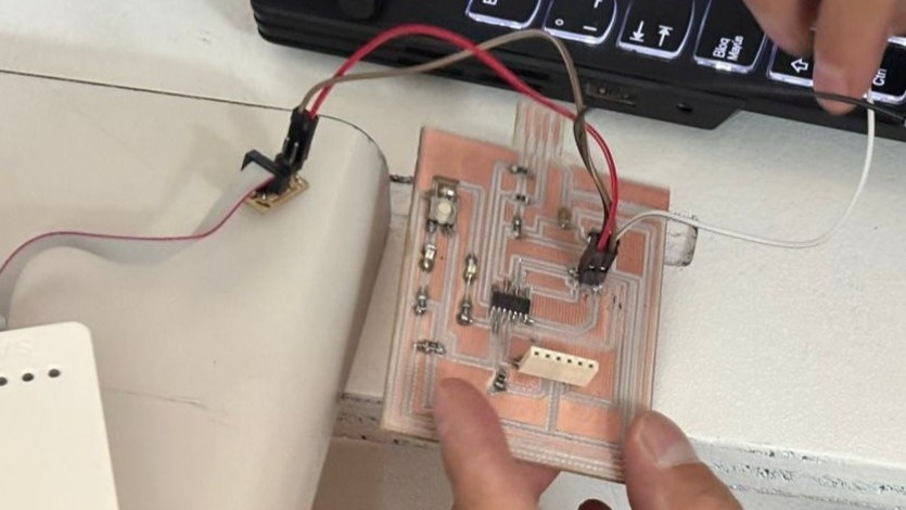
This stage marked the transition from a passive circuit to a functional system.
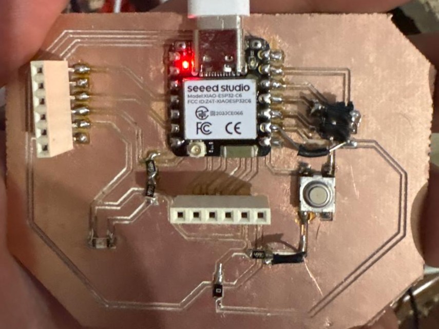
In this case, a solenoid was controlled through the PCB as part of the system developed. This test represents the transition from basic validation to a fully functional application, integrating the different elements of the developed system.
Issues and Errors
Test #1
During the milling process with the Roland MDX-20, issues were encountered when sending files from MODS, as the machine executed incorrect toolpaths or generated erratic lines. Although communication with the machine was established, it was not possible to achieve correct file transmission using Windows; different programs, configurations, and drivers were tested.
Test #2
Fab Lab repositories and documentation were reviewed, where similar cases were identified related to communication settings such as WebSocket vs WebSocket Python Serial, flow control, and the use of DB25 cables versus Serial-USB adapters. These sources suggest that the erratic behavior may be caused by inconsistencies in port configuration or communication interfaces, rather than errors in the design or generated files.
For this reason, the process was not successfully completed under this setup, and alternative solutions such as using Linux or a different machine were considered to ensure proper operation.
Test #3
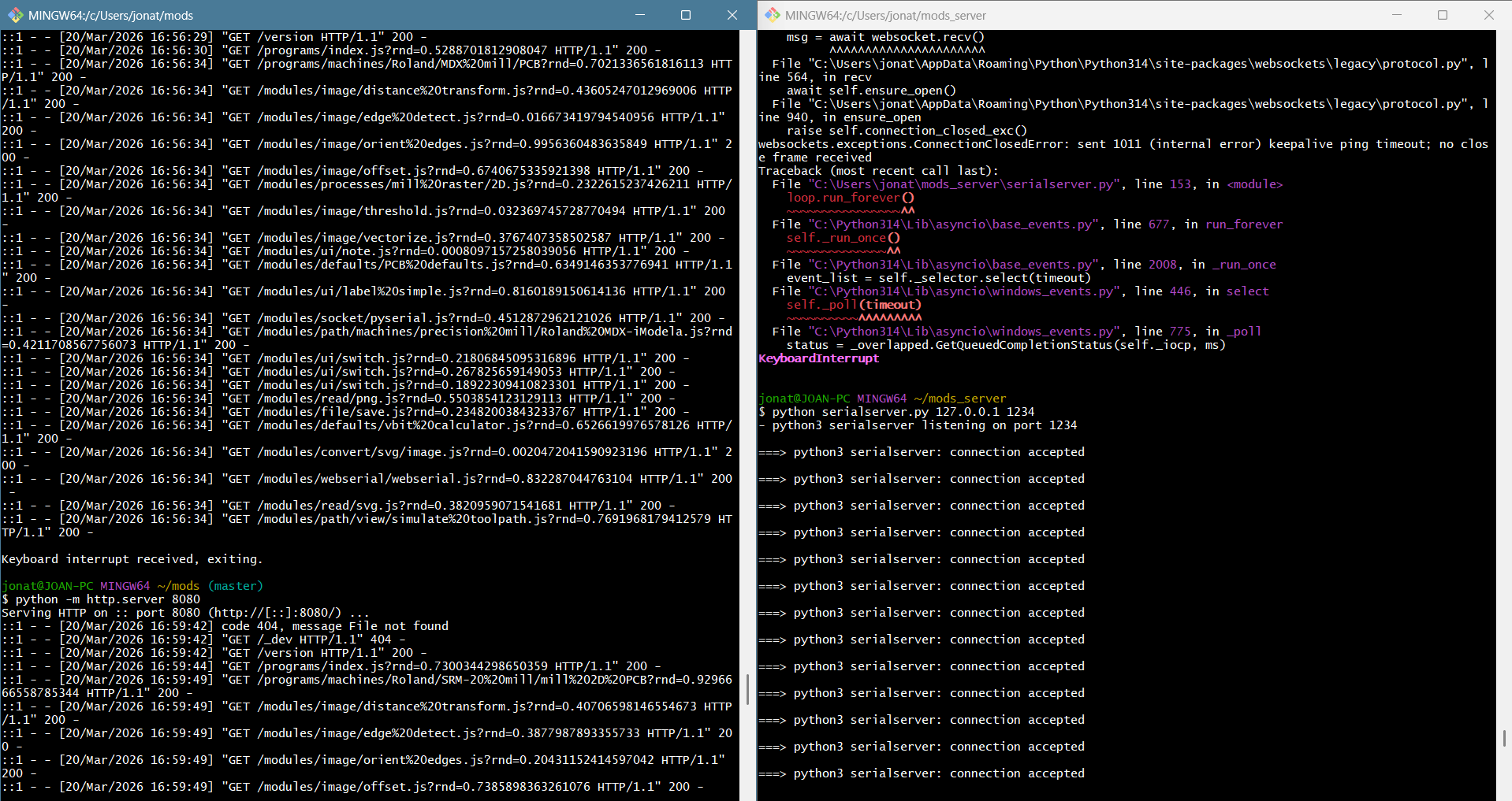
The workflow involved establishing communication between MODS and the Roland MDX-20 using a local server to run MODS, while simultaneously executing a Python serial server, serialserver.py, that acts as an interface between the system and the machine.
The serial server was configured using the address 127.0.0.1 and port 1234. Once the connection was properly established, the terminal displayed multiple connection accepted messages, indicating that communication between MODS and the serial server was successfully achieved.
During the initial tests, the connection was not always stable or correctly configured, which made it difficult to reliably send data to the machine.
It is important to mention that before achieving consistent results, several challenges were encountered during the initial tests. These issues were mainly related to the generation of RML files. A high number of offsets produced files that were too large, causing the machine to stop processing at around 30% of the job. Additionally, the use of SVG files generated erratic or excessively complex toolpaths. Week 6 Assignment
From these issues, it was understood that efficient use does not depend only on the design itself. This trial-and-error process helped to establish a more controlled and reliable workflow for PCB fabrication.
Solution
The main modification was made in the WebSocket server configuration of Neil Gershenfeld’s original serial server. The parameters ping_interval=None and ping_timeout=None were added to prevent the WebSocket connection from closing during long file transmissions from MODS to the Roland machine.
start_server = websockets.serve(
    receive,
    "127.0.0.1",
    port,
    ping_interval=None,
    ping_timeout=None
)
With this adjustment, the connection remained open while the RML file was being transmitted. This improved the stability of the communication between MODS, the Python serial server, and the Roland MDX-20.