10. Output Devices
Objectives of the Week
- Demonstrate workflows used in controlling an output device(s) with MCU board you have designed.
Schedule
Wednesday, March 25th - Output Devices
Thursday, March 26th : Basics of input devices and measurement
Friday, March 27th : Interesting input devices
Assingments
Group assignment:
- Measure the power consumption of an output device.
- Find the link to group work here
Individual assignment:
- Add an output device to a microcontroller board you’ve designed and program it to do something. (see below)
Class Work
Thursday
Thursday was a review of the realtionship between current, voltage and power and an overview of various output devices. We learned about the mechanics of motors, pulse width modulation (PWM) and several other interesting concepts and devices. A break down can be found here: Intersting components
Friday
Friday we experimented with circuits including output devices. See group work documentation linked above.
Example with custom board
Testing Output Devices
Overview
Following the previous assignment, where I tested a PIR motion sensor as an input device, the next step was to integrate and test an output device using my custom ESP32 development board.
For this test, I used a NeoPixel RGB LED connected to the ESP32. The objective was to control the LED based on input from the PIR motion sensor.
The desired behavior was:
- Motion detected: The NeoPixel turns on and emits white light.
- Motion continues: The NeoPixel remains illuminated.
- Motion stops: The NeoPixel remains on for an additional 5 seconds.
- No motion for 5 seconds: The NeoPixel turns off.
- New motion detected: The NeoPixel turns on again.
This test demonstrates how a microcontroller can process information from an input device and use it to control an output device.
Hardware Setup
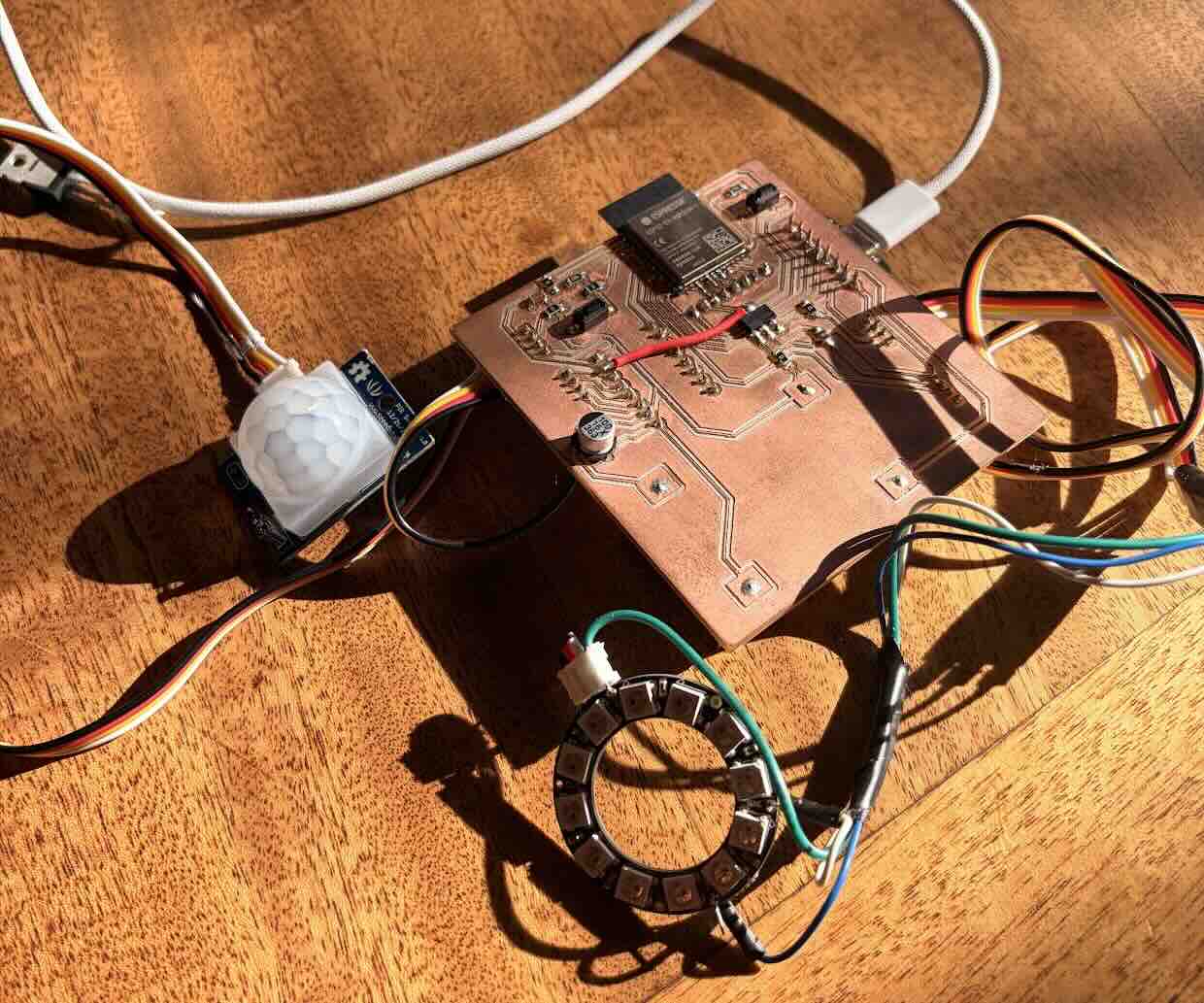
The test uses the same custom ESP32 development board developed for my final project.
The following components were connected:
- ESP32 microcontroller: Processes sensor inputs and controls the output.
- PIR motion sensor: Detects motion and sends a digital signal to the ESP32.
- NeoPixel RGB LED: Produces light based on commands from the microcontroller.
Pin Connections
| Component | ESP32 Pin | Function |
|---|---|---|
| PIR Motion Sensor | GPIO4 | Digital input |
| NeoPixel LED | GPIO18 | Digital output |
| PIR Sensor | GND | Ground |
| NeoPixel | GND | Ground |
| PIR Sensor | Power Supply | Power |
| NeoPixel | Power Supply | Power |
The PIR sensor communicates using a simple digital HIGH/LOW signal.
The NeoPixel uses a different communication method. Rather than simply switching a GPIO pin HIGH or LOW, the ESP32 sends a precisely timed digital data signal that controls the LED’s color and brightness.
Programming the NeoPixel
To control the NeoPixel, I used the Adafruit NeoPixel library.
This library simplifies communication with individually addressable RGB LEDs and provides functions for setting their color, brightness, and on/off state.
The program combines the PIR sensor input with NeoPixel control.
Arduino Code
#include <Adafruit_NeoPixel.h>

// Define pin connections
#define PIR_PIN 4          // PIR sensor connected to GPIO4
#define LED_PIN 18         // NeoPixel connected to GPIO18
#define NUM_PIXELS 1       // Number of NeoPixel LEDs

// Define how long the LED stays on after motion stops
const unsigned long offDelay = 5000;  // 5 seconds in milliseconds

// Create the NeoPixel object
Adafruit_NeoPixel pixels(NUM_PIXELS, LED_PIN, NEO_GRB + NEO_KHZ800);

// Variables to track motion and time
unsigned long lastMotionTime = 0;
bool ledOn = false;

void setup() {

  // Start serial communication
  Serial.begin(115200);

  // Configure PIR sensor as input
  pinMode(PIR_PIN, INPUT);

  // Initialize NeoPixel
  pixels.begin();
  pixels.clear();
  pixels.show();

  Serial.println("PIR and NeoPixel Test Started");
}

void loop() {

  // Read the PIR sensor
  int motionState = digitalRead(PIR_PIN);

  // Check if motion is detected
  if (motionState == HIGH) {

    // Record the current time
    lastMotionTime = millis();

    // Turn on LED if it is currently off
    if (ledOn == false) {

      Serial.println("Motion detected - LED ON");

      // Set LED color to white
      pixels.setPixelColor(0, pixels.Color(255, 255, 255));
      pixels.show();

      // Record that the LED is on
      ledOn = true;
    }
  }

  // Check if motion has stopped
  else {

    // If LED is on and 5 seconds have passed
    if (ledOn == true && millis() - lastMotionTime >= offDelay) {

      Serial.println("No motion for 5 seconds - LED OFF");

      // Turn off NeoPixel
      pixels.clear();
      pixels.show();

      // Record that LED is off
      ledOn = false;
    }
  }

  // Small delay for stability
  delay(50);
}
Understanding the Code
1. Importing the NeoPixel Library
#include <Adafruit_NeoPixel.h>
The Adafruit NeoPixel library provides the functions required to communicate with the LED.
Without this library, the microcontroller would need to generate the precise timing signals required by the NeoPixel manually.
2. Defining the Pin Connections
#define PIR_PIN 4
#define LED_PIN 18
#define NUM_PIXELS 1
These definitions establish the hardware configuration:
PIR_PIN 4identifies the GPIO pin connected to the motion sensor.LED_PIN 18identifies the GPIO pin used to control the NeoPixel.NUM_PIXELS 1specifies that only one NeoPixel LED is connected.
Using named definitions makes it easier to modify the hardware configuration without changing the rest of the code.
3. Defining the LED Off Delay
const unsigned long offDelay = 5000;
This variable defines how long the NeoPixel remains illuminated after the PIR sensor stops detecting motion.
- The value is expressed in milliseconds.
5000milliseconds equals 5 seconds.- The
unsigned longdata type is appropriate for storing time values returned bymillis().
This delay prevents the LED from immediately switching off whenever the PIR sensor temporarily stops detecting movement.
4. Initializing the NeoPixel
Adafruit_NeoPixel pixels(NUM_PIXELS, LED_PIN, NEO_GRB + NEO_KHZ800);
This creates a NeoPixel object named pixels.
The parameters define:
NUM_PIXELS: Number of LEDs connected.LED_PIN: GPIO pin used to transmit data.NEO_GRB: Color channel order used by the LED.NEO_KHZ800: Communication timing protocol.
The object allows the program to control the NeoPixel using simple library functions.
5. Tracking Motion and LED State
unsigned long lastMotionTime = 0;
bool ledOn = false;
Two variables are used to manage the LED:
lastMotionTimestores the most recent time that motion was detected.ledOnrecords whether the NeoPixel is currently illuminated.
The bool data type stores either true or false.
Tracking the LED state prevents the program from repeatedly sending the same command when the LED is already on.
6. Initializing the Hardware
Inside the setup() function:
Serial.begin(115200);
pinMode(PIR_PIN, INPUT);

pixels.begin();
pixels.clear();
pixels.show();
These commands:
- Initialize serial communication.
- Configure the PIR sensor pin as an input.
- Initialize communication with the NeoPixel.
- Clear any existing LED color settings.
- Send the updated state to the NeoPixel, ensuring it starts turned off.
The setup() function runs only once when the ESP32 starts.
7. Reading the Motion Sensor
int motionState = digitalRead(PIR_PIN);
The program continuously reads the PIR sensor.
The result is stored in motionState.
HIGH: Motion is detected.LOW: No motion is detected.
The result determines whether the LED should be turned on or whether the off-delay timer should continue.
8. Turning On the NeoPixel
if (motionState == HIGH) {

  lastMotionTime = millis();

  if (ledOn == false) {

    pixels.setPixelColor(0, pixels.Color(255, 255, 255));
    pixels.show();

    ledOn = true;
  }
}
When motion is detected:
- The current time is recorded using
millis(). - The program checks whether the LED is already on.
- If the LED is off, its color is set to white.
- The new color is transmitted to the NeoPixel.
- The LED state is updated to
true.
Understanding RGB Color
The following command sets the LED color:
pixels.setPixelColor(0, pixels.Color(255, 255, 255));
NeoPixels use RGB color values.
| Color Channel | Value |
|---|---|
| Red | 255 |
| Green | 255 |
| Blue | 255 |
Each channel can typically be assigned a value between 0 and 255.
Setting all three channels to their maximum value produces white light.
9. Turning Off the NeoPixel
else {

  if (ledOn == true && millis() - lastMotionTime >= offDelay) {

    pixels.clear();
    pixels.show();

    ledOn = false;
  }
}
When no motion is detected, the program checks whether enough time has passed to turn off the LED.
The condition:
millis() - lastMotionTime >= offDelay
calculates the elapsed time since motion was last detected.
If at least 5 seconds have passed:
pixels.clear()sets the LED color to zero.pixels.show()sends the updated state to the NeoPixel.ledOn = falserecords that the LED is now off.
If motion is detected again before the 5 seconds have elapsed, lastMotionTime is updated and the countdown effectively restarts.
10. Using millis() Instead of delay()
One important aspect of this program is the use of millis() to control the LED off-delay.
Unlike delay(), which pauses program execution, millis() returns the time elapsed since the microcontroller started running.
This allows the program to:
- Continuously monitor the PIR sensor.
- Keep the LED illuminated.
- Track elapsed time.
- Respond to new motion without waiting for a blocking 5-second delay.
The program still includes a short delay(50) at the end of the loop, but this only pauses execution for 50 milliseconds.
Results
The test demonstrates the integration of an input device and an output device using the custom ESP32 development board.
The PIR sensor provides a digital input signal, which the microcontroller processes to control the NeoPixel.
The expected behavior is:
| PIR Sensor State | NeoPixel Behavior |
|---|---|
| Motion detected | LED turns on |
| Motion continues | LED remains on |
| Motion stops | LED remains on for 5 seconds |
| No motion for 5 seconds | LED turns off |
| New motion detected | LED turns on again |
Serial Monitor Output
The program also provides feedback through the Arduino IDE Serial Monitor.
An example of the expected output is:
PIR and NeoPixel Test Started
Motion detected - LED ON
No motion for 5 seconds - LED OFF
Motion detected - LED ON
Reflection
This exercise built on the previous input-device assignment by introducing control of an external output device.
The most important concepts demonstrated were:
- Input/output integration: Using information from a PIR sensor to control an LED.
- Digital communication: Understanding the difference between reading a simple digital input and sending timed data to an addressable LED.
- State management: Using a Boolean variable to track whether the LED is on or off.
- Time-based control: Using
millis()to implement a delay without stopping the main program for several seconds.
This functionality is directly relevant to my final project, which uses motion detection to activate a lighting system.
The test provides a foundation for integrating the lighting behavior into the final mechanical and electronic assembly.