9. Input Devices
Objectives of the Week
- Understand the concept of input devices
- Practice basic circuitry incorporating input devices
- Demonstrate workflows used in sensing something with input device(s) and MCU board
Schedule
Wednesday, March 18th - Input Devices
Thursday, March 19th : Basics of input devices and measurement
Friday, March 20th : Interesting input devices
Assingments
Group assignment:
- Probe an input device(s)’s analog levels and digital signals (As a minimum, you should demonstrate the use of a multimeter and an oscilloscope.)
- Document your work on the group work page and reflect on your individual page what you learned
Individual assignment:
- Measure something: add a sensor to a microcontroller board that you have designed and read it.
Class Notes and Work
This week we learned about input devices and how to trouble shoot.
- We stared with a simple circuit that incldued a potenciometer and fixed resitence. Using a multmeter, we could see the realtive resistence of the potenciometer change as we turned the dial.

- Our second circuit included a flame sensor and fixed resistance. We connected this circuit to an oscilloscope to visualise the change in resistence across the flame sensor as we exposed it to heat.

Independant Work
As part of the individual assigment I built a circuit which utalized capacitive touch.
The code
The code for this was interesting because, when the sensor is touched, each light turns on after a different delay. It also reads the temerature sensor from the Barduino board are returns a human readible value. There were two primary challenges assocaited with creating this code.
Challenge 1: The temperature sensor requires a special library. In order to return human readible values I downloaded the library “Temerature_LM75” and loaded the library by including
    #include <Temperature_LM75_Derived.h>
    Generic_LM75 temperature;
Challenge 2: To turn the lights on when the sensor was touched, I created a threshold. When the voltage registered by the capacitive touch device reached the threshold it triggered the light to turn on.
    long threshold = 60000;
    .
    .
    .
    void loop() {
    long signal = touchRead(touchPin);
The full source code can be seen here.
Code
    /*
    Read the temperature from an LM75-derived temperature sensor, and display it
    in Celcius every 250ms. Any LM75-derived temperature should work.
    */

    // The Generic_LM75 class will provide 9-bit (±0.5°C) temperature for any
    // LM75-derived sensor. More specific classes may provide better resolution.

    #include <Temperature_LM75_Derived.h>
    Generic_LM75 temperature;

    int touchPin = 12;
    int redPin   = 13;
    int greenPin = 14;
    int bluePin  = 15;
    int singleyellowPin = 11;
    int singleredPin  = 10;

    long threshold = 60000;

    void setup() {
    Serial.begin(115200);

    pinMode(redPin, OUTPUT);
    pinMode(greenPin, OUTPUT);
    pinMode(bluePin, OUTPUT);
    pinMode(singleyellowPin, OUTPUT);
    pinMode(singleredPin, OUTPUT);

    while(!Serial) {}
    Wire.begin();
    }

    void loop() {
    long signal = touchRead(touchPin);

    if (signal > threshold) {
        digitalWrite(redPin, LOW);
        digitalWrite(greenPin, HIGH);
        digitalWrite(bluePin, HIGH);
        Serial.println("touched");
        delay(350);
        digitalWrite(singleyellowPin, HIGH);
        delay(350);
        digitalWrite(singleredPin, HIGH);
    } else {
        digitalWrite(redPin, HIGH);
        digitalWrite(greenPin, LOW);
        digitalWrite(bluePin, LOW);
        Serial.println("not touched");
        delay(350);
        digitalWrite(singleyellowPin, LOW);
        delay(350);
        digitalWrite(singleredPin, LOW);
    }

    Serial.print("Temperature = ");
    Serial.print(temperature.readTemperatureC());
    Serial.println(" C");

    delay(100);
    }
Example with Custom Board
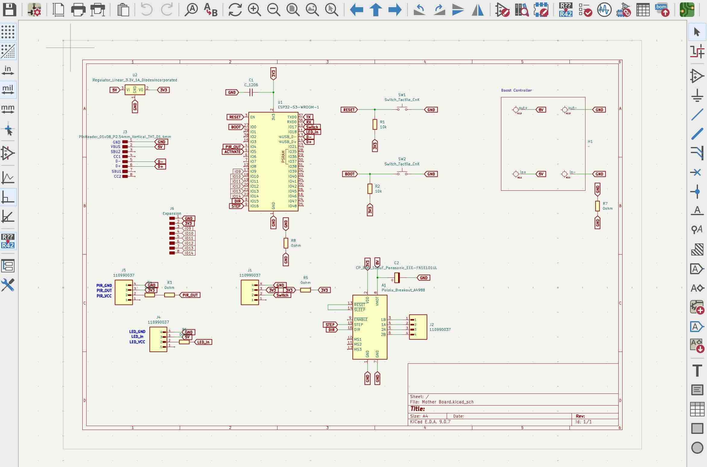
Custom Board Schematic
For this example, I used the custom ESP32 development board designed and fabricated as part of my final project.
For more information about the board design, see the PCB Design section of the Final Project documentation.
Reading Input from a PIR Motion Sensor
Based on the schematic, the PIR motion sensor is connected to GPIO4 on the ESP32.
The PIR sensor detects changes in infrared radiation caused by movement and sends a digital signal to the microcontroller.
- HIGH (approximately 3.3 V): Motion detected.
- LOW (approximately 0 V): No motion detected.
The following Arduino program reads the digital signal from GPIO4 and prints a message to the Serial Monitor indicating whether motion has been detected.
The code is heavily commented to explain each step involved in reading an input device.
Arduino Code
// Define GPIO4 as the pin connected to the PIR sensor.
// PIR_PIN is a name we can use instead of writing 4.

#define PIR_PIN 4

// The setup() function runs once when the ESP32
// powers on or is reset.

void setup() {

  // Start serial communication at 115200 bits per second.
  // This allows the ESP32 to send messages to your computer.

  Serial.begin(115200);

  // Configure GPIO4 as an input.
  // The ESP32 will read the voltage from the PIR sensor.

  pinMode(PIR_PIN, INPUT);

  // Print a message to the Serial Monitor once at startup.

  Serial.println("PIR Motion Sensor Test Started");

}

// The loop() function runs continuously
// as long as the ESP32 is powered.

void loop() {

  // Read the digital state of GPIO4.
  // HIGH = approximately 3.3V (motion detected).
  // LOW  = approximately 0V (no motion).

  // Store the result in an integer variable named motionState.

  int motionState = digitalRead(PIR_PIN);

  // Check whether the PIR sensor output is HIGH.

  if (motionState == HIGH) {

    // If HIGH, print "motion detected" to the Serial Monitor.

    Serial.println("motion detected");

  }

  // If the condition above is false, execute this block.

  else {

    // Print "no motion" to the Serial Monitor.

    Serial.println("no motion");

  }

  // Pause the program for 500 milliseconds (0.5 seconds).
  // This prevents the Serial Monitor from being flooded.

  delay(500);

}
Understanding the Code
The program follows a simple sequence:
-
Define the input pin
#define PIR_PIN 4assigns the namePIR_PINto GPIO4.
-
Initialize serial communication
Serial.begin(115200)establishes communication between the ESP32 and the computer.
-
Configure the input
pinMode(PIR_PIN, INPUT)configures GPIO4 to receive the PIR sensor’s signal.
-
Read the sensor
digitalRead(PIR_PIN)reads the current digital state of GPIO4.
-
Evaluate the input
- If the signal is
HIGH, the program printsmotion detected. - If the signal is
LOW, the program printsno motion.
- If the signal is
-
Repeat
- The program waits 500 milliseconds before reading the sensor again.
Results
The PIR motion sensor was connected to my custom ESP32 development board using jumper cables.
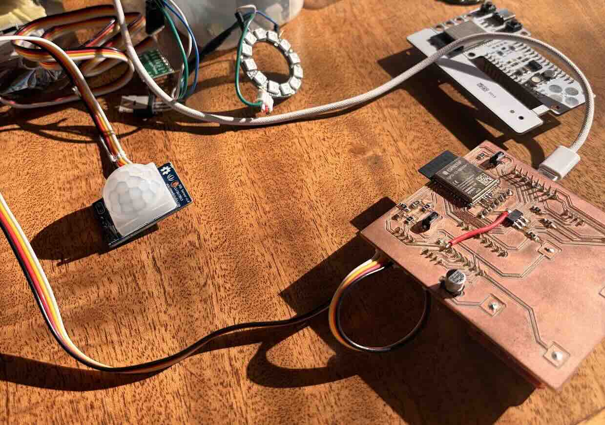
The program provides a simple method for testing the sensor by displaying its output in the Arduino IDE Serial Monitor.
The expected output is:
PIR Motion Sensor Test Started
no motion
no motion
motion detected
motion detected
no motion
This test demonstrates how an external input device can be connected to a custom microcontroller board, read through a GPIO pin, and interpreted using a simple conditional statement.