3. Computer Controled Cutting
Objectives of the Week
- Demonstrate and describe parametric 2D modelling processes.
- Identify and explain processes involved in using the laser cutter.
- Develop, evaluate and construct a parametric construction kit.
- Identify and explain processes involved in using the vinyl cutter.
Schedule
Wednesday, Feb 4th: - Global Class - Computer Controled Cutting
Thursday, Feb 5th: - Cutting and Parametrics 1 Password: 4RL7Cv%G
Friday, Feb 6th: - Cutting and Parametrics 2 Password: w!4SA%GL
Class Notes
Parametric design - a design based on parameters - when you change a parameter the design changes automatically
Lazer Cutter 1. 2D cutting, marking, engraving 2. Materials: can cut a wide variety of materials depending on the equipment. Generally can not cut metal 3. Key parameters tuned for cutting different materials are: speed and power 4. deep nest: open source tool for optimizing nesting - DEEPNEST.io 5. need to account for lazer thinkness: kerf - can create the required offset in the CAD design (using parametrics) or in the CAM software
Vynal Cutter - Used for cutting thin, realtively soft materials: paper, vynal, fabric… - Key parameters are blade type, cut depth, speed
Assignments
Group assignment:
-
Do your lab’s safety training
-
Characterize your lasercutter’s focus, power, speed, rate, kerf, joint clearance and types.
-
Document your work to the group work page and reflect on your individual page what you learned.
Link to the group assignment page
Individual assignments:
-
Design, lasercut, and document a parametric construction kit, accounting for the lasercutter kerf.
3a. Explained how you created your parametric design:
See parametric design section for Fusion & Grasshopper
3b. Documented how you made your press-fit construction kit.
Group Project Parametric_Comp
3c. Reflect on your individual page what you learned of your labs safety training See lazer cutter and vynel cutting notes below
-
Cut something on the vinyl cutter.
4b. Documented how you made something with the vinyl cutter.
4c. Included your original design files.
4d. Included hero shots of your results.
Cutting Documentation and Examples
Lazer cutting
Class Notes
- follows two coordinates (no z)
- uses vector to cut, raster, engrave
- G-code: very basic language that the matchines use. It is 90% coordinates (X,Y,Z)
-
cuts using a lazer
- old ones used light
- most now use CO2
-
What we can do here in Barcelona
-
Materials: plastics, wood, cardboard, fabric, need to be consiensous of refelctivity, some materials are more expensive than others
-
do a preliminary test with a cheap material to make sure it looks good
-
thinkness: varries by material but typically limited to 8mm
- this is limitation is due to the focal point of the laser. Not the thinkness of the material
-
Parameters: power, speed, frequency, air compressor (only have this off if you are cutting paper or textiles)
-
-
Ways to create 3d forms: stacking, cross section, bending, there is a plug in to fusion that does this automatically
-
Sending Files
-
make sure file has layers with: raster, inner edge, outer edge
-
make sure the colors of the layers are set appropriately
-
steps
-
Open the file on the lazer cutting computer
-
open the file in Rhino
-
File —> print to the correct matchine
-
make sure the scale is 1:1 and you do not scale to the selected area
-
this will automatically open the CAM software
-
-
place material in the bed and move the laser to the corner (top left)
-
-
Lazer Cutting Example
Laser Cutting Test: Hardwood Veneer and Parametric Assembly
1. Overview
This test explored the process of using a laser cutter to fabricate a small assembly kit from hardwood veneer. The primary objectives were to determine appropriate cutting settings, evaluate kerf width, and establish a reliable workflow for preparing and cutting geometry generated using parametric design tools.
The equipment used was a Glowforge laser cutter, which is designed to prioritize accessibility and ease of use. Compared with more advanced industrial laser cutters, the Glowforge offers relatively limited control over certain machine parameters and cutting operations. Although the simplified interface makes the equipment approachable, achieving accurate and consistent results still requires experimentation, material testing, and careful preparation of cutting files.
The experiment focused on three primary challenges:
- Identifying cutting settings that consistently penetrate the material without excessive burning.
- Accounting for laser kerf to produce accurately fitting components.
- Preparing and organizing cutting geometry to improve cutting efficiency and prevent material movement during fabrication.
Two hardwood veneer species, cherry and walnut, were tested at nominal thicknesses of 1/16 inch. An additional test was conducted using 3/16-inch walnut.
2. Objectives
The specific objectives of the experiment were to:
- Determine suitable laser speed and power settings for different hardwood veneers.
- Measure the kerf produced by the laser to inform dimensional compensation.
- Develop parametric geometry for an assembly kit with accurately sized joints.
- Establish a workflow for transferring geometry from CAD software through Inkscape into Glowforge.
- Control the cutting sequence to minimize material movement and incomplete cuts.
- Identify common fabrication issues and develop practical solutions.
3. Equipment and Materials
Equipment and Software
- Laser cutter: Glowforge
- CAD software: Parametric modeling software for generating test and assembly geometry
- Vector editing software: Inkscape
- Laser control software: Glowforge web-based interface
Materials
| Material | Nominal Thickness | Purpose |
|---|---|---|
| Walnut hardwood | 3/16 in (4.76 mm) | Initial cutting feasibility test |
| Cherry hardwood veneer | 1/16 in (1.59 mm) | Kerf testing and assembly fabrication |
| Walnut hardwood veneer | 1/16 in (1.59 mm) | Kerf testing and assembly fabrication |
Material thicknesses are nominal. Actual thickness can vary between sheets and should be measured before generating final assembly geometry.
4. Methodology
Step 1: Generate Kerf Test Geometry
The first step was to create a simple test geometry to evaluate the width of material removed by the laser during cutting.
Kerf is the width of material removed by the cutting process. Because a laser beam has a finite width, the resulting cut does not follow the theoretical design line without removing material on either side. Kerf becomes particularly important when fabricating interlocking components, such as press-fit joints, slots, and tabs. For example, a slot designed to be exactly the same width as the material thickness may become too loose after cutting because the laser removes additional material from both sides of the slot.
A kerf test can be performed by cutting a series of precisely dimensioned features and measuring the resulting dimensions with calipers.
For a simple external test piece:
Kerf = Designed Width - Measured Width
For an internal slot:
Kerf = Measured Slot Width - Designed Slot Width
These calculations assume the laser follows the centerline of the programmed geometry and that dimensional changes from material movement or charring are negligible.
Recommended procedure:
- Create several rectangular test pieces or slots with known dimensions.
- Cut the geometry using the intended material and cutting settings.
- Measure the resulting dimensions using digital calipers.
- Calculate the effective kerf width.
- Repeat measurements across multiple features to identify inconsistencies.
- Use the measured kerf to adjust the parametric assembly geometry.
For press-fit assemblies, additional tolerance testing may be necessary because material compression, grain direction, and surface charring can influence the final fit.
My sample kurf test generated in Fusion
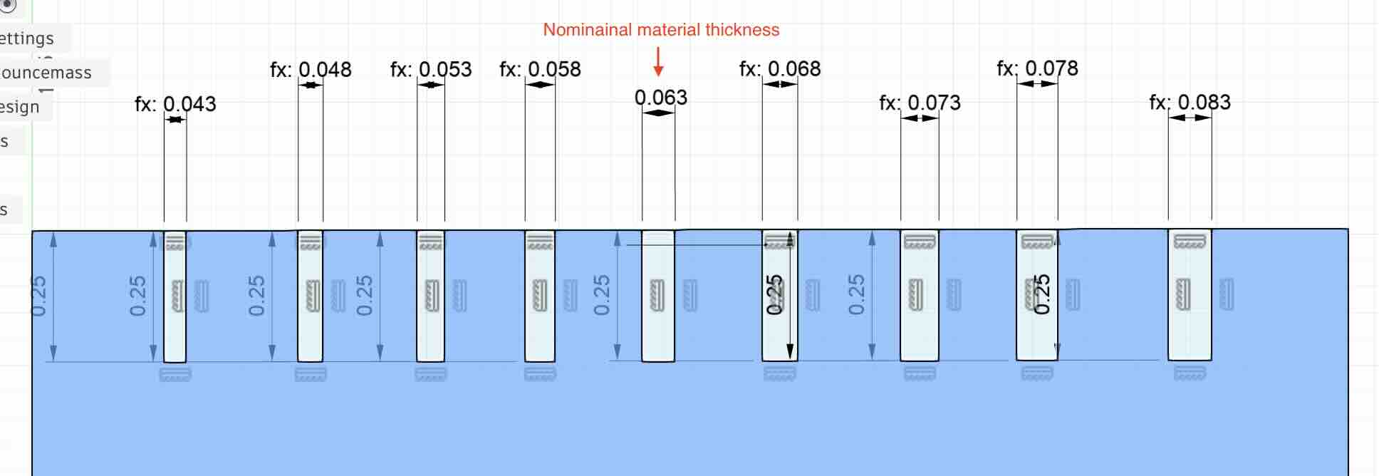
**Example of how parametric values should be incorporated. **
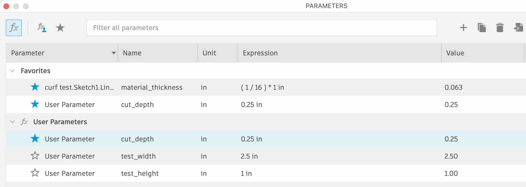
In image above shows the kurf set to my nomical material thickness with systematic variations of .005 inches.
Step 2: Determine Laser Cutting Settings
After generating the kerf test geometry, the file was exported and imported into the Glowforge software.A series of cutting tests was conducted to determine suitable speed and power settings for each material.The primary criteria for evaluating a successful cut were:
- Complete penetration: The laser must cut through the full material thickness.
- Minimal edge burning: Excessive charring should be avoided to preserve appearance and dimensional accuracy.
- Dimensional consistency: The cut should follow the intended geometry without significant distortion.
- Repeatability: The same settings should produce consistent results across multiple cuts.
Laser cutting speed and power are closely related.
- Speed: Determines how quickly the laser moves along the cutting path. Lower speeds generally increase the amount of energy delivered per unit length.
- Power: Controls the laser output. Higher power generally increases cutting capability but can also increase burning and heat-related damage.
The objective was to find the fastest reliable cutting speed at a suitable power level while maintaining acceptable edge quality.
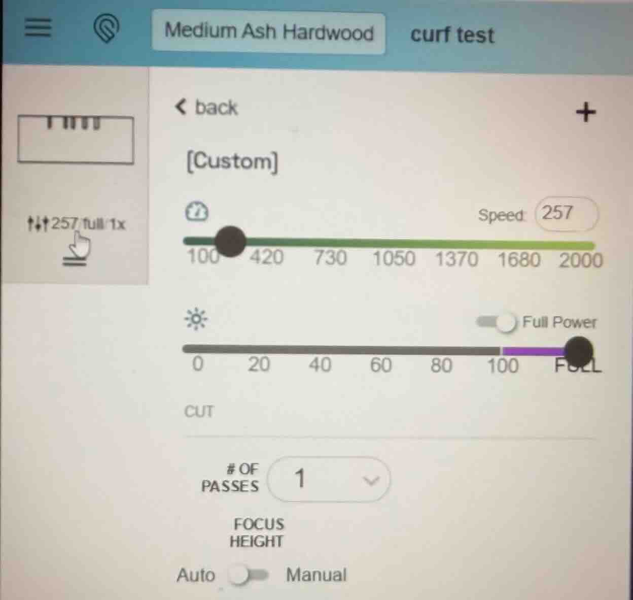
Laser Cutting Settings and Test Results
The following tests were performed to determine appropriate settings for the different hardwood materials.
Speed and power values are recorded using the Glowforge interface settings rather than physical units.
| Material | Test # | Speed | Power | Result |
|---|---|---|---|---|
| 3/16 in Walnut | 1 | 100 | 100 | Did not cut through. Significant burning and visible flames. Material considered unsuitable for the tested cutting conditions. |
| 1/16 in Cherry | 2 | 750 | 85 | Did not cut through. |
| 1/16 in Cherry | 3 | 750 | 100 | Did not cut through. |
| 1/16 in Cherry | 4 | 100 | 100 | Cut through successfully, but with excessive edge burning. |
| 1/16 in Cherry | 5 | 250 | 100 | Successful cut with minimal edge burning. Selected settings. |
| 1/16 in Walnut | 6 | 250 | 100 | Did not cut through. |
| 1/16 in Walnut | 7 | 150 | 100 | Successful cut with minimal edge burning. Selected settings. |
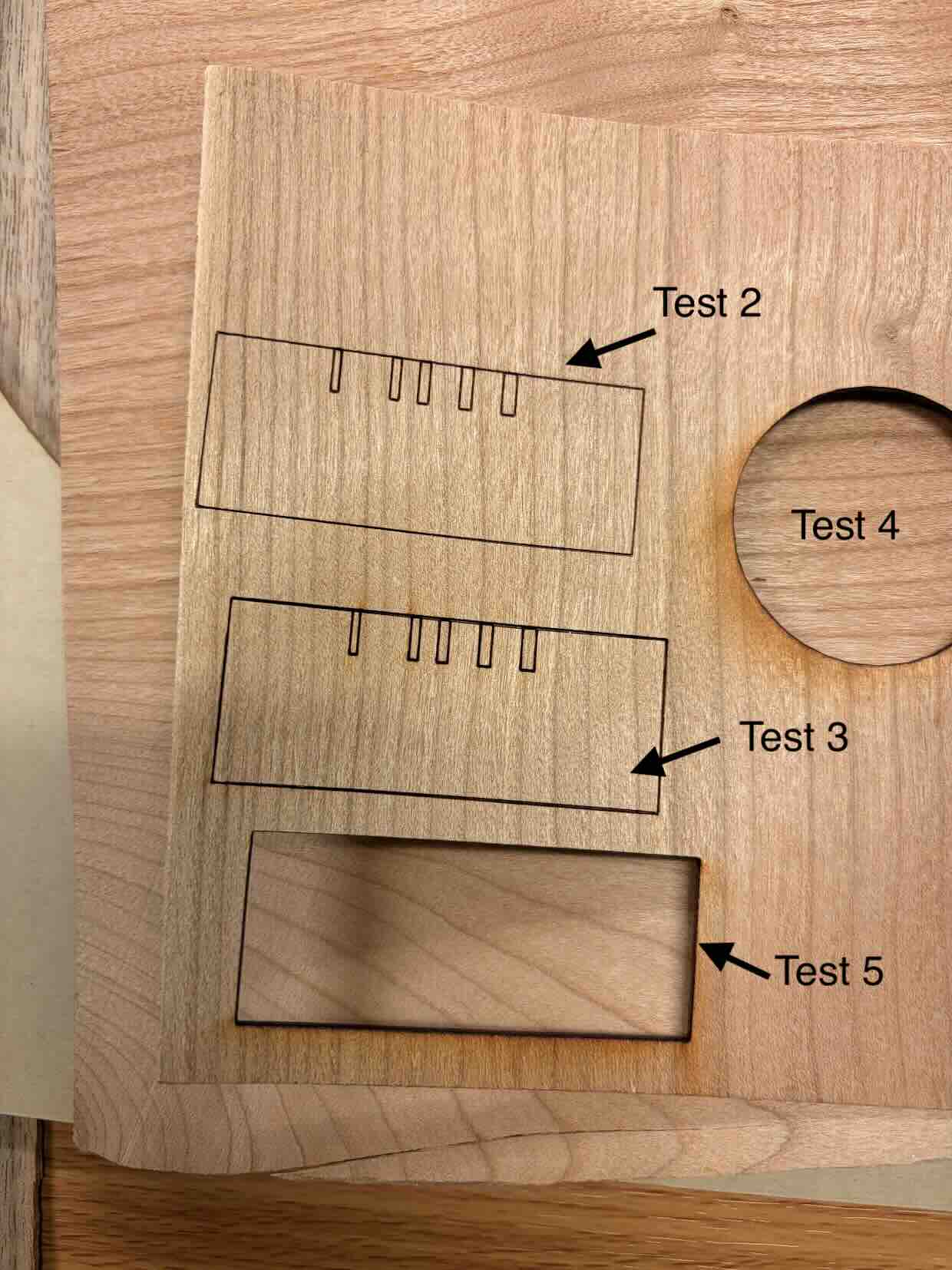
Selected Cutting Settings
| Material | Speed | Power | Outcome |
|---|---|---|---|
| 1/16 in Cherry | 250 | 100 | Complete penetration with minimal burning |
| 1/16 in Walnut | 150 | 100 | Complete penetration with minimal burning |
These settings represent the best results observed during this experiment and should not be considered universally applicable.
Actual cutting performance may vary depending on material density, moisture content, veneer construction, machine condition, and other factors.
Interpretation of Results
Material thickness
The initial test using 3/16-inch walnut demonstrated that the material could not be reliably cut under the tested conditions. Even at the slowest tested speed and maximum power, the laser failed to penetrate the material and produced significant burning and visible flames.
This indicated that the material was unsuitable for the selected cutting approach. Further attempts would require a different strategy, potentially including multiple passes where supported and appropriate, or the selection of thinner material.
Visible flames also indicate a potential fire hazard. Cutting should be stopped if sustained flaming occurs, and the material should not be left unattended.
Cherry veneer
The initial tests at a speed of 750 failed to cut through the 1/16-inch cherry veneer, even when power was increased from 85 to 100.
Reducing the speed to 100 at full power produced complete penetration but excessive burning. Increasing the speed to 250 maintained complete penetration while substantially improving edge quality.
Walnut veneer
The settings that worked successfully for cherry did not produce complete penetration in walnut of the same nominal thickness.
At a speed of 250 and power of 100, the walnut remained incompletely cut. Reducing the speed to 150 at full power produced a successful cut with minimal burning.
This suggests that the two materials responded differently to the laser despite having similar nominal thicknesses. Differences in density, grain structure, moisture content, and material composition may have contributed to the different cutting behavior.
Step 3: Generate Parametric Assembly Geometry
Once the kerf and material thickness had been evaluated, the assembly kit geometry was generated using parametric design tools. Parametric modeling allows key dimensions to be controlled through adjustable variables rather than manually modifying individual features.
Important parameters included:
- Material thickness
- Kerf width
- Joint and slot dimensions
- Component dimensions
- Assembly clearances
Using these parameters makes it possible to modify the design for different materials without rebuilding the entire model.
For example, if the material thickness changes or a different kerf is measured, the slot dimensions can be updated automatically. The geometry was then exported into a vector-compatible format for further preparation.
Step 4: Prepare Cutting Files in Inkscape
The exported geometry was imported into Inkscape to organize the cutting paths before transferring them to Glowforge.
This step was important because the Glowforge software did not consistently execute the cutting operations in the desired order.
The preparation process included:
- Importing the exported CAD geometry into Inkscape.
- Inspecting the geometry for overlapping or duplicate lines.
- Removing unnecessary or repeated cutting paths.
- Separating geometry into groups based on the desired cutting sequence.
- Exporting the groups as separate files.
- Adding a common bounding box to preserve alignment between the files.
The bounding box provided a consistent reference for positioning the individual files after importing them into Glowforge.
Cutting order was particularly important for small parts and internal features. Internal details should generally be cut before the outer perimeter of a component. Otherwise, a part may become detached from the surrounding sheet and shift before its remaining features are cut.
Step 5: Import and Cut the Final Geometry
The prepared files were imported into Glowforge individually.
Because the cutting groups did not transfer as separate controllable layers from Inkscape, each group had to be saved and uploaded separately. The bounding boxes were used to align the individual cutting groups. The cutting sequence was then manually controlled to reduce the risk of components becoming detached prematurely.
Before cutting, the material was checked for flatness and positioned on the cutting bed.
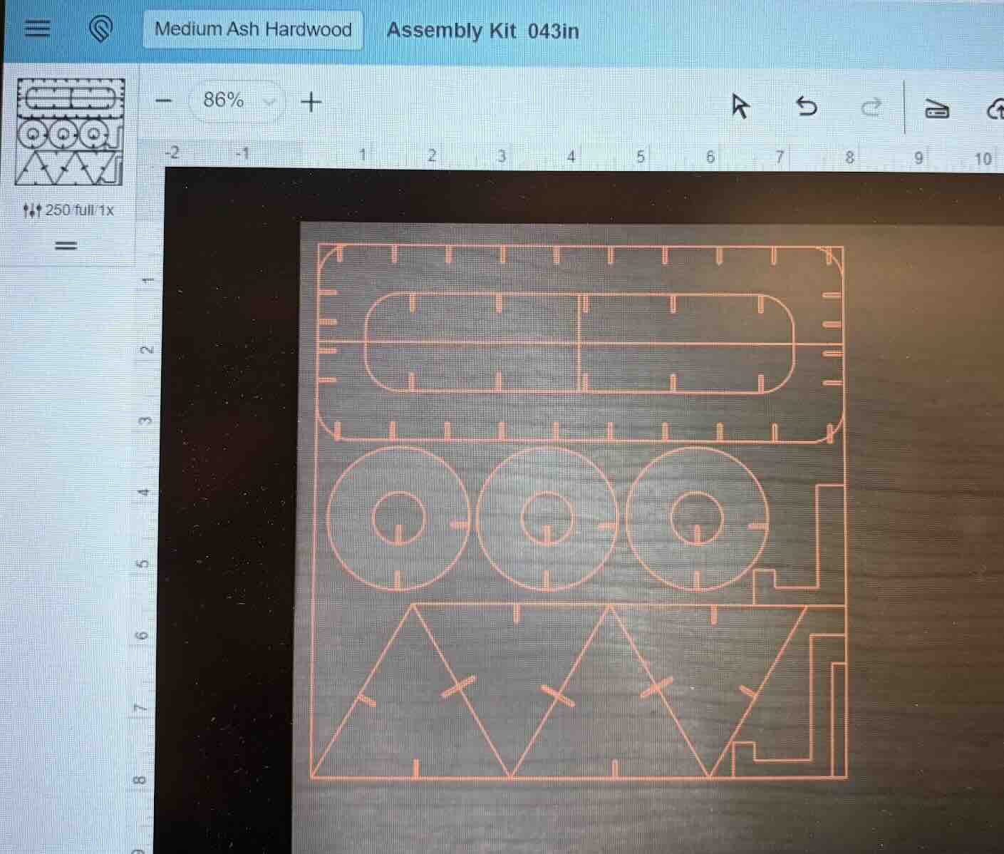
The selected cutting settings were applied according to the material being used.
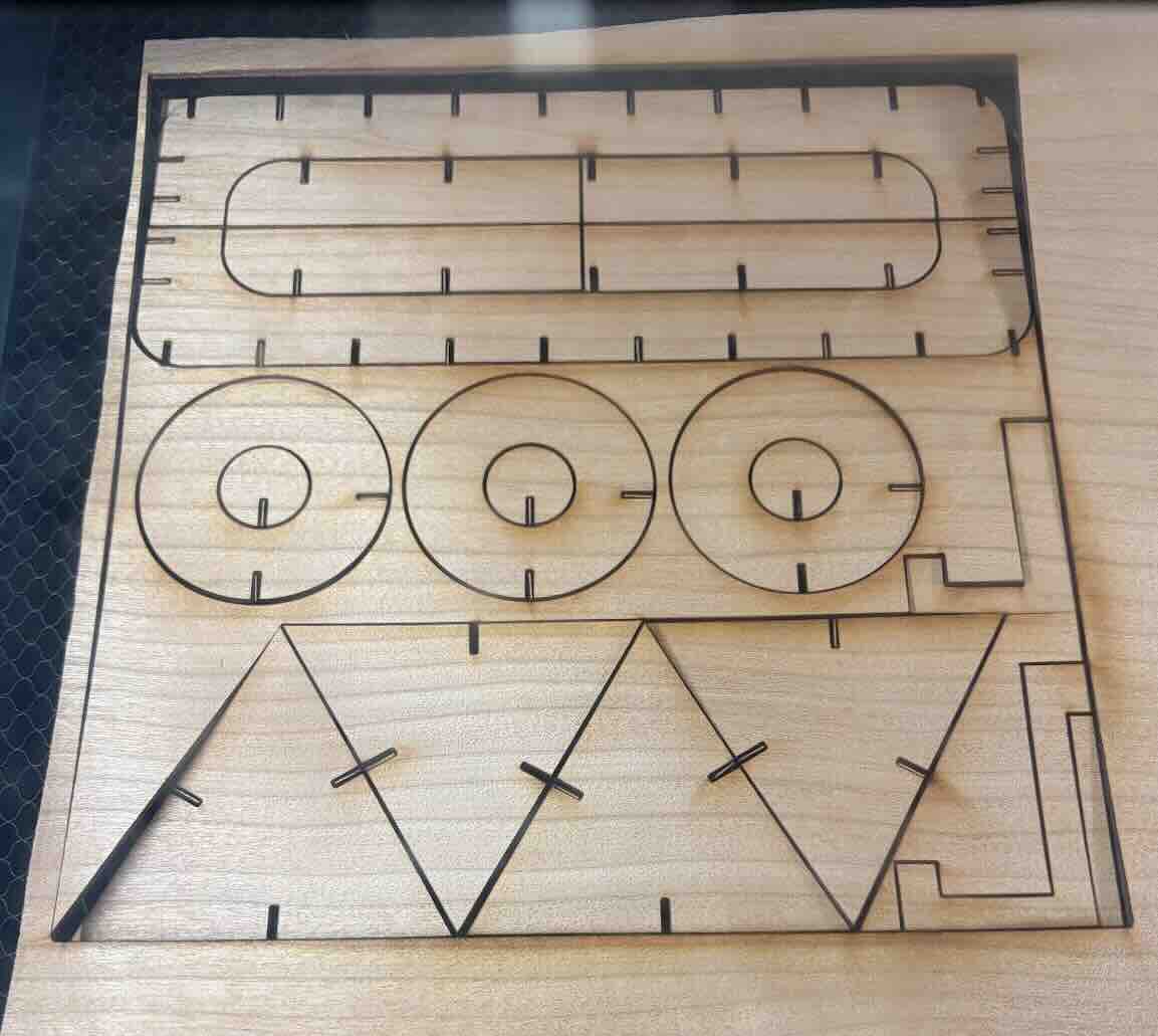
Step 6: Assemble and Evaluate
After cutting, the components were removed from the material sheet and assembled.
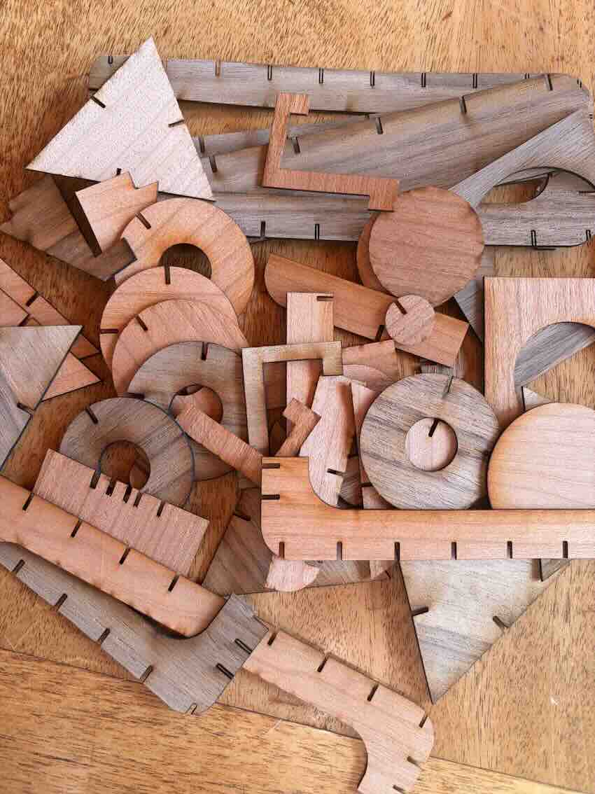
The final assembly
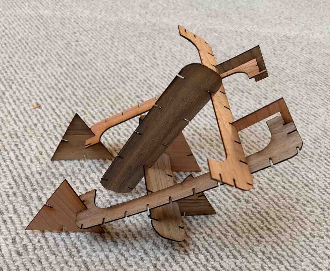
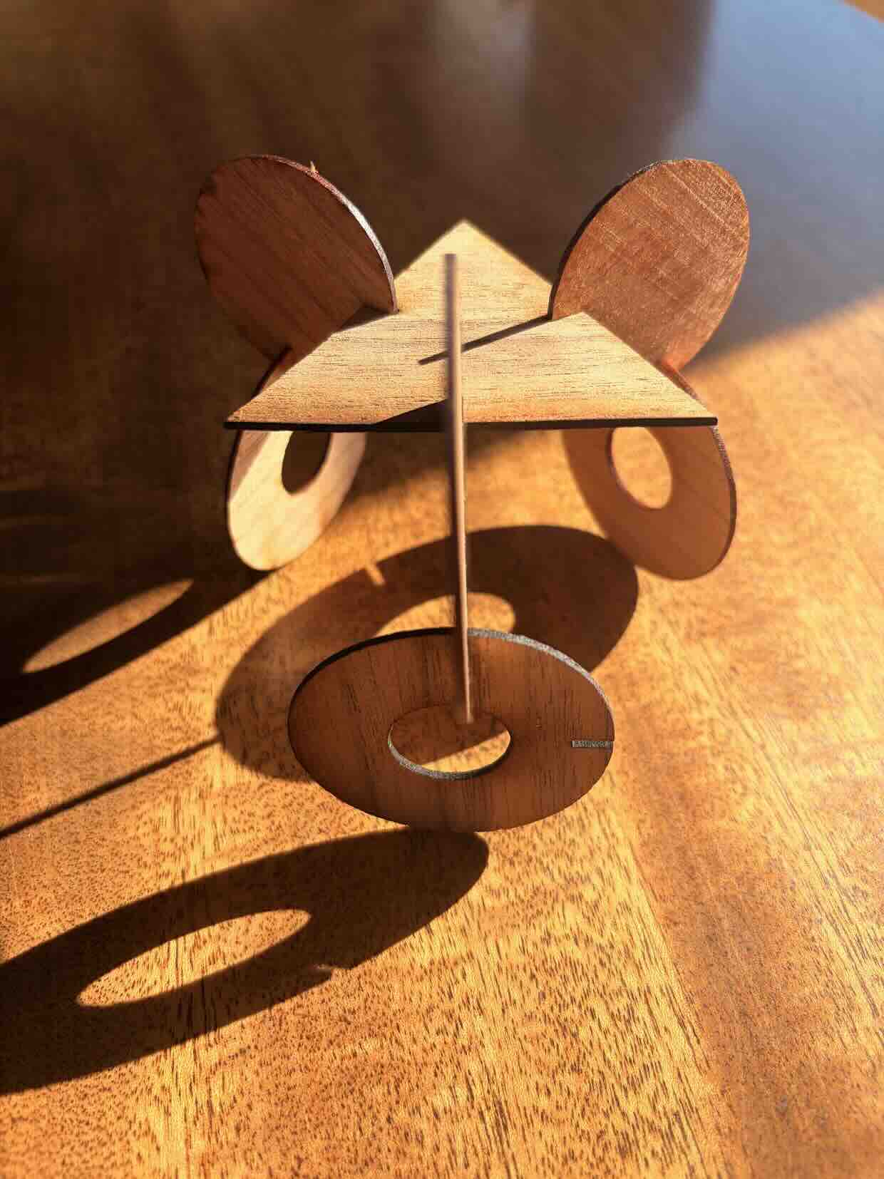
Overall the assembly was fun to play with, rearrange and generate interesting shapes. The fit of pieces was nice and snug creating solid attachments but the material in general is flimsy and easily breakable across grain.
Takeaway: The material lends itself to very small arrangements. Over large diestnaces it is breakable and flexible.
Click to download Assembly Kit Design
6. Problems Encountered and Solutions
Issue 1: Unpredictable Cutting Order
Problem
The Glowforge software did not always execute individual cutting paths in the intended order.
This created problems when external outlines were cut before internal details. Once a component was fully separated from the surrounding material, it could shift or fall slightly, affecting subsequent cuts.
Solution
The cutting geometry was reorganized in Inkscape into separate groups corresponding to the desired cutting sequence.
However, these groups did not import into Glowforge as independently controllable layers.
To work around this limitation:
- Each cutting group was saved as a separate file.
- A common bounding box was included as an alignment reference.
- The files were imported into Glowforge individually.
- The cutting sequence was manually controlled.
This allowed internal features to be cut before external perimeters.
Lesson Learned
Cutting order should be considered during file preparation rather than relying on the laser software to determine an appropriate sequence automatically.
A consistent inside-to-outside cutting strategy reduces the likelihood of part movement and incomplete cuts.
Issue 2: Uneven or Warped Material
Problem
Some of the veneer sheets were not sufficiently flat against the cutting bed.
This created two related issues:
- Components could shift or fall after being separated from the surrounding sheet.
- Variations in material height could affect laser focus and produce inconsistent kerf widths.
Because laser cutting depends on maintaining an appropriate focal distance between the laser optics and the material surface, uneven material can result in inconsistent cutting performance.
In extreme cases, warped material may produce incomplete cuts or visibly distorted edges.
Solution
Controlling the cutting sequence reduced some of the problems caused by material movement.
However, this did not fully resolve the issue when the material itself was significantly warped.
A more reliable solution is to:
- Select flatter material before cutting.
- Store veneer in a manner that minimizes warping.
- Flatten material before fabrication when appropriate.
- Secure the material using compatible hold-down methods that do not interfere with the laser head.
- Verify that the material remains within the machine’s allowable focus range.
Lesson Learned
Material preparation is as important as machine calibration.
Even well-calibrated cutting settings may produce inconsistent results when the material is not flat.
Issue 3: Duplicate and Overlapping Cutting Lines
Problem
Some exported geometry contained overlapping or duplicate lines.
When these lines were imported into the cutting software, the laser could execute the same cutting path more than once.
This caused several problems:
- Increased cutting time
- Unnecessary energy consumption
- Additional burning and charring
- Potential widening of the kerf
- Reduced dimensional accuracy
Duplicate lines are particularly problematic in assemblies with shared edges or repeated geometry.
Solution
The geometry was inspected in Inkscape before being imported into Glowforge.
Overlapping and duplicate paths were identified and removed so that each intended cut was represented by a single cutting line.
Lesson Learned
Vector geometry should always be inspected and cleaned before laser cutting.
Removing duplicate paths improves efficiency and reduces unnecessary heat exposure.
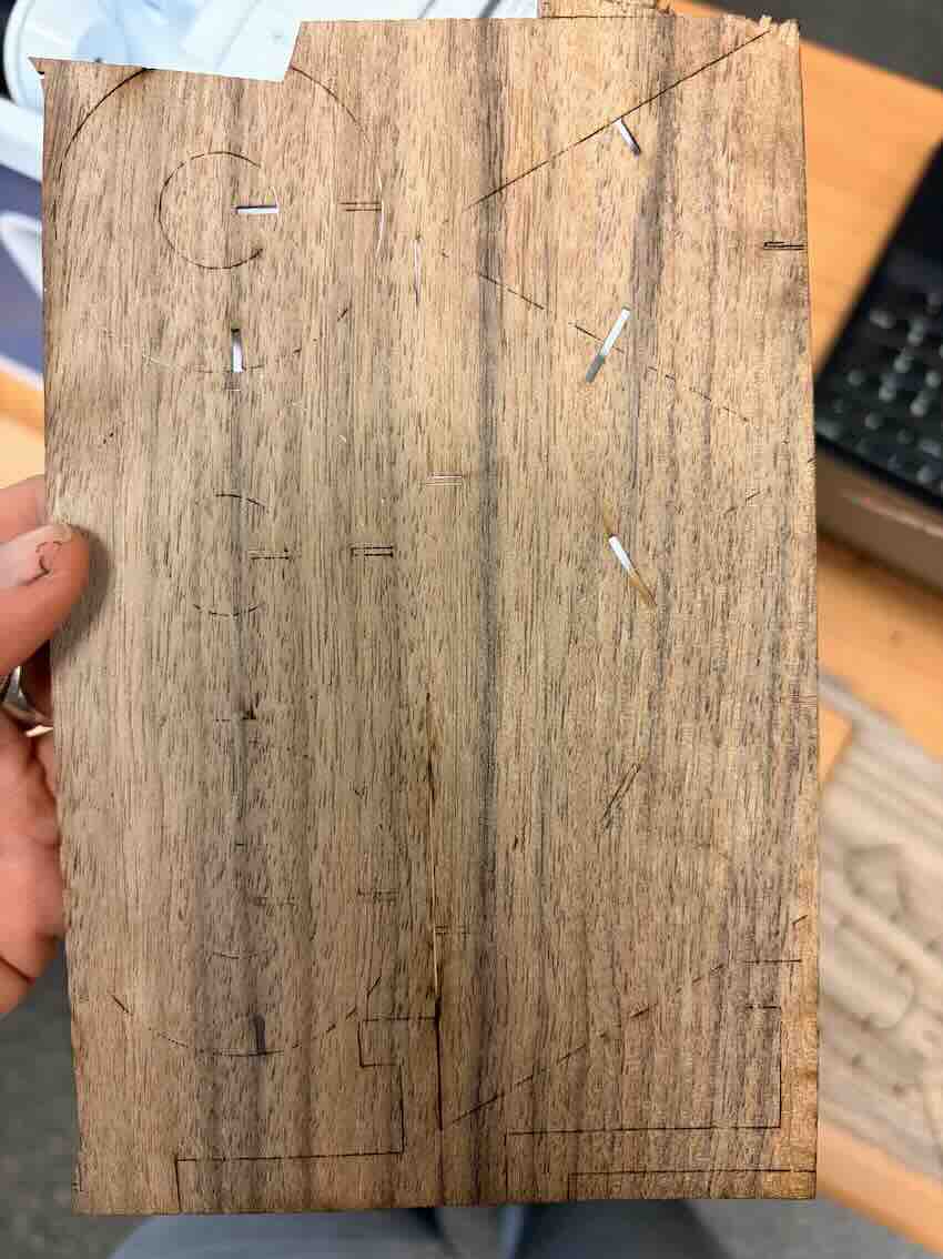
Issue 4: Different Cutting Settings for Similar Materials
Problem
Cherry and walnut veneers had the same nominal thickness of 1/16 inch, so it was initially assumed that they would require similar cutting settings.
However, the settings that successfully cut cherry did not completely penetrate walnut.
This required additional testing and adjustment.
Explanation
Laser cutting performance depends on more than material thickness.
Potential contributing factors include:
- Density: Different wood species may require different amounts of energy for cutting.
- Grain structure: Variations in wood anatomy can influence cutting consistency.
- Moisture content: Water within the material can affect the energy required for cutting.
- Material composition: Natural oils, resins, adhesives, and other constituents may affect the cutting process.
- Surface characteristics: Differences in material appearance and absorption may influence how the material responds to the laser.
The experiment demonstrated that nominally similar materials should not automatically be assumed to have identical cutting behavior.
Solution
Separate cutting tests should be performed for each material type before cutting the final assembly.
In retrospect, the kerf test should also have been repeated for both cherry and walnut, since changes in cutting settings may affect the resulting kerf.
Lesson Learned
Cutting settings and kerf measurements should be treated as material-specific parameters.
A successful configuration for one wood species should be considered a starting point rather than a validated setting for another.
7. Key Takeaways
The experiment demonstrated that reliable laser cutting requires more than selecting a material and importing a design into the machine.
Although Glowforge simplifies many aspects of laser cutting, successful fabrication still depends on careful testing, accurate geometry, and an understanding of material behavior.
The most important findings were:
-
Cutting parameters are material-specific. Cherry and walnut required different speeds despite having the same nominal thickness.
-
Higher energy does not always produce better results. Cutting too slowly can result in excessive burning, while cutting too quickly may prevent complete penetration.
-
Kerf compensation is essential for accurate assemblies. The amount of material removed during cutting must be considered when designing interlocking components.
-
Cutting sequence affects reliability. Internal features should generally be cut before external outlines to prevent parts from moving prematurely.
-
Material flatness affects cutting accuracy. Warped sheets can produce inconsistent focus, distorted kerf, and incomplete cuts.
-
Clean vector geometry improves efficiency. Removing duplicate lines reduces cutting time and prevents unnecessary burning.
-
Parametric modeling supports rapid iteration. Using material thickness and kerf as adjustable parameters makes it easier to adapt the design to different materials and cutting conditions.
8. Conclusion
The laser cutting test successfully identified workable cutting settings for 1/16-inch cherry and walnut hardwood veneers using a Glowforge laser cutter.
The selected settings were:
- Cherry: Speed 250, Power 100
- Walnut: Speed 150, Power 100
Both configurations produced complete cuts with minimal visible edge burning under the tested conditions.
The experiment also highlighted several limitations in the fabrication workflow, including unpredictable cutting order, material warping, duplicate geometry, and differences in cutting behavior between wood species.
These issues were addressed through improved vector file preparation, manual control of cutting sequences, and material-specific testing.
For future projects, the most important improvement would be to establish a standardized calibration process for each material before producing the final assembly.
Combining measured material thickness, kerf testing, parametric design, and organized cutting files should improve dimensional accuracy, reduce material waste, and make the overall fabrication process more repeatable.
Note: Exact numerical kerf measurements and final assembly tolerances were not included in the original test notes. These should be recorded in future experiments to validate the dimensional accuracy of the completed assembly.
Vynal cutting example
Class Notes
-
other interesting uses
- silk screens
- cutting iron on lettering for shirts
- inflatables using thermo adhesive
- copper tape for soft circut
-
files
- must mirror images and words if you care about the direction
-
materials
- anything you can easily cut with an exacto knife
- card stock
- paper
- coper tape (good for soft circuits)
-
Software
- siluette studios
- doesnt allow .sbg (most common) save as .dxf
- templatemaker.ml for free templates
- siluette studios
-
Cutting
- paste small pieces on the clear sheet
- turn the matchine on
- connect with bluetooth or with cord
- from material drop down select the most similar material. If you arent sure you should do a small test
- make sure wheles are on notches
- align edge of mat with small line on the left
- Optional - click generate test, send test
Vinal Cutting Example
- from inkscape save as svg
- go to cloudconvert to convert to dxf
- open silhoutte studios
- open dxf file in sillouete studios
-
preparing image
- select all and group
- resize by dragging corners

-
preparing cut settings
- select closest material from dropdown
- gnerate test using button on lower left
- run test to determine if inital settings are correct
- try to remove the test with a pair of tweezers. If it removes cleanly you can proceed with the cut

-
Final Result
