2. Computer Aided Design
This week focuses on CAD modling including: raster, vector, 2D, 3D models and terms and tools such as raster, vector, render. In order to explore and learn the basics of various software we will model a possible final project and share it through compressed images and videos.
Schedule
Wednesday, Jan 28th: - Global Class - Principles and Practices
Thursday, Jan 29th: - CAD Overview, FreeCAD and Rhino Password: *B85VA8Y
Friday, Jan 30th: - CAD with Fusion Password: PJyNd4w*
Assignment
- Model experimental objects/part of a possible final project in 2D and/or 3D software
- Show how you did it with words/images/screenshots (see below)
- Document how you compressed your image and video files here
- Include your original design files
Notes from class
Global Class Notes
Global Class Notes
General types of modeling
- use simples shapes to make more complex shapes: join, subtract…
- function representation: coding
- mesh: push and pull a mesh
Constructive modeling - Basic ways to create geomentry
- extrude a sketch
- moving a cross section
- rotateing a sketch
- lofting: creats surface that joins lines
- fitting shapes together using boolean operations
- Sketch on surfaces of 3d geometry (can use this to create further 3d shapes)
Rendering tools
- some tools have better rendering
History
- ability to go back to any step along the process
- allows you to revert to any point
- this is not true of all software
- very important to consider
- minimizes the need to save religiously
Constraints
- equal, tangent, parallel, perpendiculat, consentric…
- typically available in tools more designed for engineering (constructive geometry)
Assemblies
- conditions you can impose on shapes relative to each other
Paramentric Styles:
-
speadsheet of named dimesions and equations wish include things like hole diameters, sizes…
-
node-based visual programming where varying inpust varies output 3d modeling
Simulation
- set things up so you can move them around with a slider
- analytic
- mechanical analysis
- start with paper calcs
- use comon sense
- should use for continous behavior of materials
Documenting with video
- kdm live (free)
Wrapping Up
- most important thing to be familiar with after this week is parametric design beucase we will need this for next week.
- Assignement: represent final prject in as many ways as possible
- possible to transfer between software but can cause issues
Friday Class
Pixel or raster images vs vector images
- pixel (colored squares) located on a gird
- works very well with images, shading, gradient
Vectors
- the geometric (mathematical) represetation of a shape
- images are made out of accumulated layers of shapes
- required for fabrication
- can be scaled infinately
- Way of getting vector images
- vectorizing tools
- specific computer software
-
- photoshop can save vector images
CAD basic taxonomy
- Grab image from slides
- Raster tools
- Gimp (free)
- Krita (free)
Affinity (adobe competitor, free)
- by Canva: marketing, information presentation tool
Mechanics
- boolean operators:
- merging two shapes
- join
- subtract
- overlap only
- not overlaped only
- cut path - breaks the shapes when they overlap
- fracture - breaks all the shapes at hte point where they overlap
Mesh modeling
- a mesh is a collection of vertices, edges and faces
Notes from lego modeling
- create the array of voids before aligning with primary shape
- to create the camferes, create an array first then center
- can hide elements to see better
Rino
- commands make design much faster.
- you can start typing the first letters of the command
- make sure you are constructing in the corrent plane
- most common keys are
- right click
- enter: repeats previous command
- space
- Gumball - allows you to pull and drag compenents
- When you drag to select
- right to left: selects everything it touches
- left to right: selects only things completely contained
- command click to deselect
- hold shift to lock in a direction of movement
- use properties window to change perspectives of the camera
CAD Program exploration
3D tools
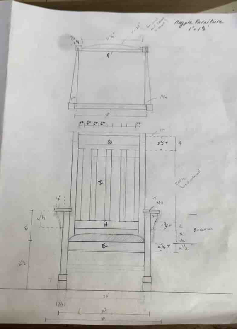
Given that I will be running a custom furniniture buisness after this course, I have a very specific and practical application for the CAD software that I choose. It is important that I learn the tool that is most effective for me long term. Becuase of this, I chose to model an example project that is representative of how I might use these tools on a day to day basis.
The rocking chair below is a example of a project in which I would use CAD. Based on the in class excersise modeling the lego I ruled out blender as a long term modeling tool and focused primarily on Fusion and Rhino.
Original Design
I am including 3D program documentation on seprate pages beucase I will continue to update these throughout the course. Tutorial and original design files for this weeks exploration as well as ongoing updates can be found at the links below.
Fusion
Fusion documentation can be found here Fusion
Rhino
Rhino documenation can be found here Rhino
2D tools
Pixel or raster images vs vector images
- pixel (colored squares) located on a gird
- works very well with images, shading, gradient
Vectors
- the geometric (mathematical) represetation of a shape
- images are made out of accumulated layers of shapes
- required for fabrication
In order to apply a 2D design to a surface, the image needs to be a vector. Tools such as Adobe illustrator and Inkscape allow you to design directly in vectors but it is also common to convert a raster image to a vector image in order to apply an existing image to a 2D or 3D design
This work flow walks thorugh the vectorization of an image. This means converting JPG or other pixel-based images into a series of vector paths.
The following workflow demonstrates one possible method.
The exact process depends heavily on the software and tools available.
Workflow Overview
In this example:
- Photoshop is used to simplify the image
- Inkscape is used to vectorize the image
Photoshop Workflow
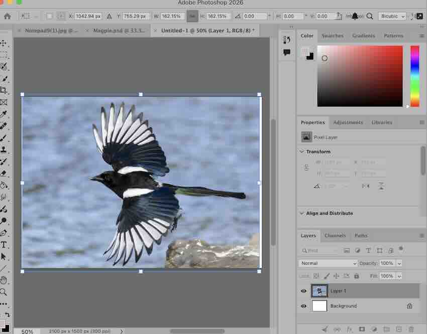
- Open the image on a new layer
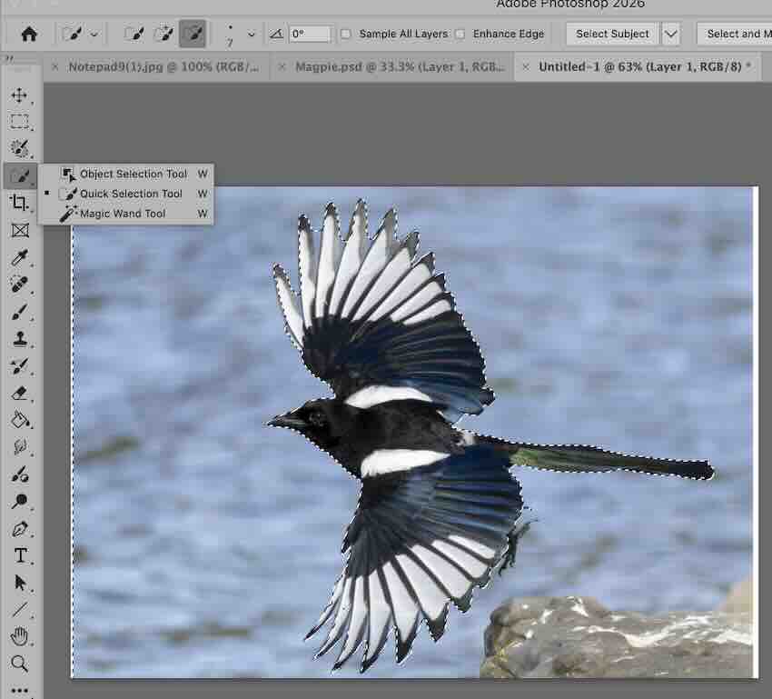
- Use the Quick Selection Tool to select the portion of the image you want to keep
- Delete the background or unnecessary content
- Use the eraser tool to clean up edges and details
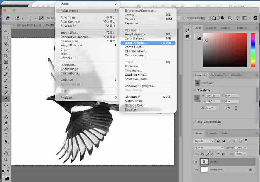
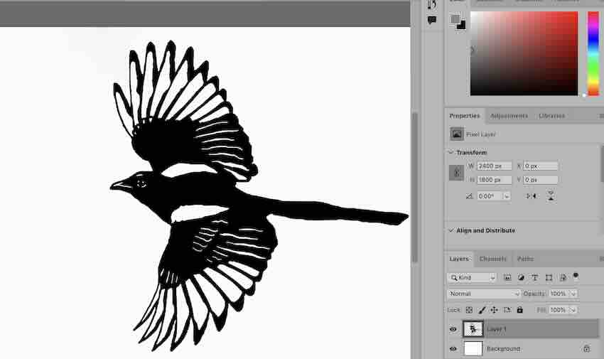
- Convert the image to black and white
- If working with color:
- Use thresholds to simplify the color palette
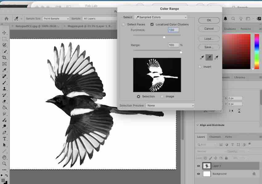
- Use Select → Color Range to reduce the image into several colors rather than a full spectrum
- Select the positive image
- Use Select Inverse to select the white areas
- Delete the inverse selection to remove lighter shades
- Select inverse again to reselect the dark portions
- Fill with black
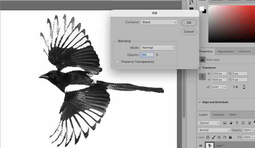
- Add back required details using the eraser tool
Inkscape Workflow
Preparing the Image
- In Photoshop:
- Simplify color ranges
- Reduce image complexity
- Save as
.jpg
Converting an Image to Vector
In Inkscape:
- Go to:
File → Import Bitmap- Choose Embed
- Import the bitmap onto the canvas
Trace Bitmap
- Select the bitmap
- Go to:
Path → Trace Bitmap
In the Mode tab:
- Choose:
- Colors
- Enable:
- Smooth
- Disable:
- Stack scans
- Enable:
- Delete background
Adding Text
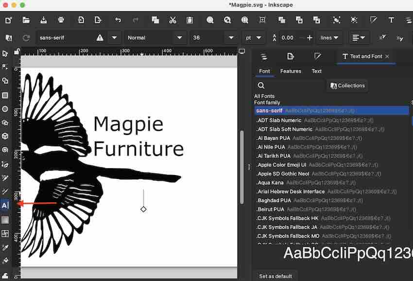
- Use the Text Tool in the lower-left corner of the Inkscape window
- Text settings can be edited in the text editor
- Accessed via the “T” icon in the upper-right menu
Additional Notes
- Reduce the number of scans until the object is clear
- For black and white images, this is usually 2 scans
- Adjust smoothing and optimization settings
- Helps preserve detail
- Prevents blocky edges
- You may need to refresh the preview between changes

Image and Video Compression
As part of this weeks assignment we are required to demostrate image and video compression. Images on this page as well as videos found on the 3D Fusion documentation are examples of the final product.
The process for file compression is documented under References and Info —> Development Notes —> How to resize images and videos Link to Development Notes