7. Computer Controled Machining
Objectives of the Week
-
Demonstrate 2D design development for CNC milling production
-
Describe workflows and operation for large format CNC machining
Schedule
Wednesday, March 4 - Global Class - Computer Controled Machining
Thursday, Feb 26: - Local lab safety training
Friday, Feb 27: - Local practice
Assignments
Group assignment:
-
Complete your lab’s safety training
-
Test runout, alignment, fixturing, speeds, feeds, materials and toolpaths for your machine
-
Document your work to the group work page and reflect on your individual page what you learned
Individual Assignment:
Click to download Side table design file
Setting up in Fusion
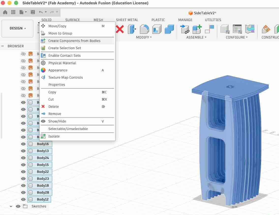
Convert Bodies to Components
Before arranging the parts, convert each body into an individual component.
Arrange Components
Navigate to:
Modify → Arrange
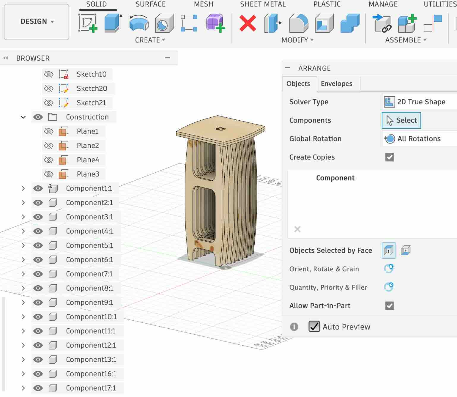
Objects Tab
In the Objects tab:
- Select all of the components you would like to arrange.
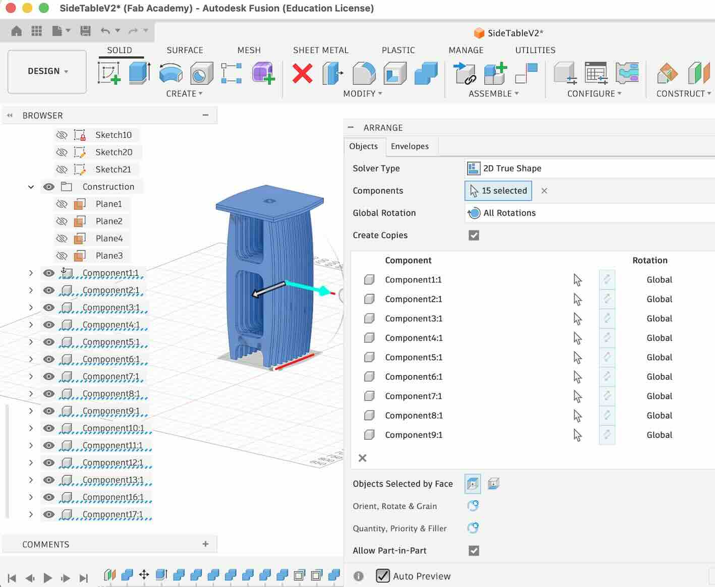
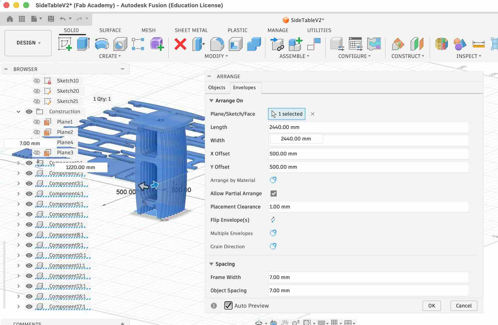
Envelope Tab
Switch to the Envelope tab.
- Select the plane onto which the components will be projected.
- Enter the dimensions of your stock material (length and width).
- Use the Preview function to verify that all components fit within the available material.
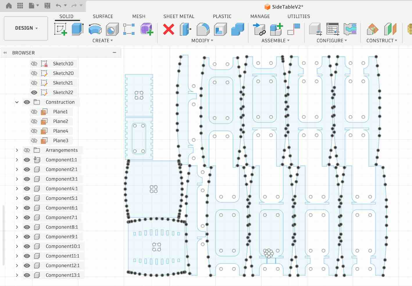
Project Geometry into a Sketch
Once the arrangement is complete, project the geometry into a sketch.
- Press P to activate the Project tool.
- Select the sketch plane.
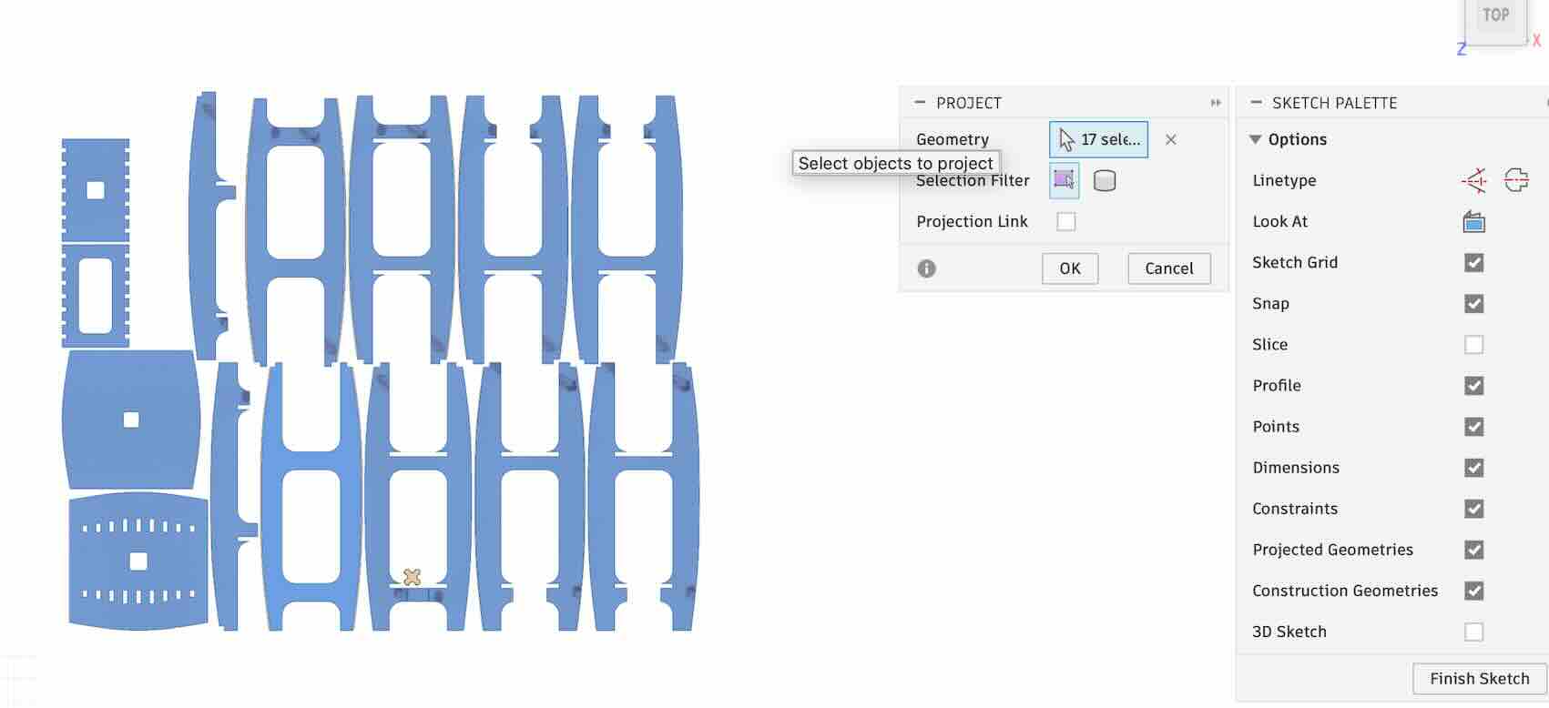
Next, select the faces whose profiles you would like to project.
Tips
- Select only the minimum geometry required.
- Avoid selecting unnecessary edges or vertices.
- Disable “Projection Link”.
- This creates an independent sketch that can be edited without affecting the original model.
Prepare the Sketch for CNC
Hide the arranged components so that only the sketch remains visible.
The sketch lines should appear light blue.
- If any lines appear purple, they are still linked to the original geometry.
- Edit the projection and disable Projection Link.
Modifying Internal Corners
All internal corners must be modified to accommodate the diameter of the cutting tool.
For this project a 6 mm end mill was used, meaning that no inside corner can be sharper than the cutter radius.
Several techniques can be used, including dog-bone fillets.
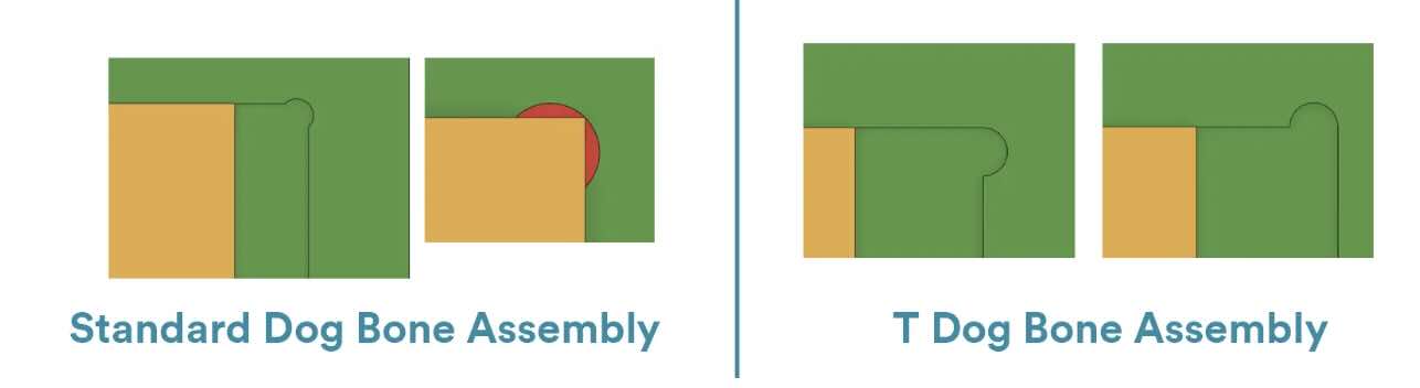
Source: https://ecoreprap.com/cnc-machining/how-to-get-square-inside-corners-in-cnc-machining/
Exporting to Rhino
Once the sketch is complete:
- Select all sketch geometry that will be cut.
- Extrude the profiles to any small thickness.
- This preserves editable geometry when importing into Rhino.
- Save the design as a new file.
- Remove all geometry and sketches that are not intended for machining.
- Export the model as a STEP (.step) file.
- Transfer the file to the lab computer (using a USB drive) equipped with the RhinoCAM plugin.
Setting up the File in RhinoCAM
Import the STEP File
- Open the exported STEP file in Rhino with the RhinoCAM plugin installed.
Prepare the Geometry
To avoid duplicate toolpaths, only keep a single copy of each cutting profile.
- Switch to the Side View.
- Select only the top layer of geometry.
- Move the selected geometry to a new layer.
This ensures there are no overlapping or duplicate curves when generating toolpaths.
- Join all curves to create continuous closed paths.
- Delete the original layer containing the duplicate geometry.
Add Screw Locations
Draw points indicating the screw locations used to secure the stock material during machining.
When placing screws:
- Ensure every part is either:
- secured by one or more screws, or
- connected to the stock material using bridges (tabs).
Proper work holding is essential to prevent parts from shifting during machining.
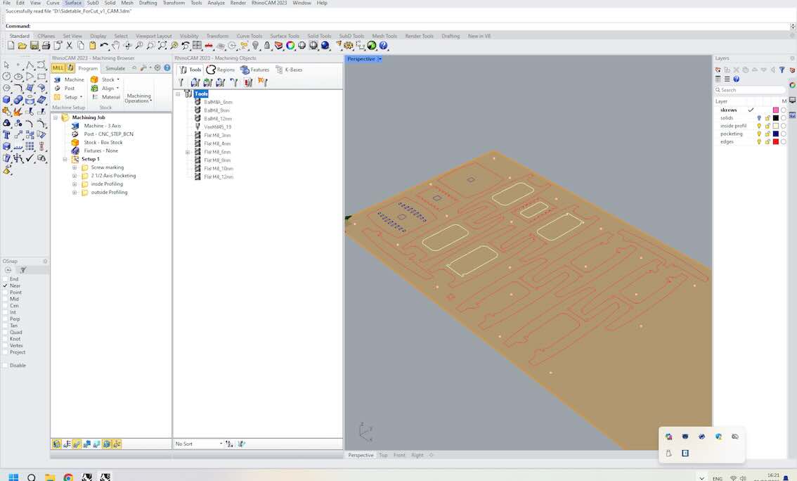
Organize Geometry into Layers
Separate the geometry into individual layers based on the machining operation.
Keeping each operation on its own layer makes CAM setup significantly easier and reduces the chance of selecting the wrong geometry.
A typical layer organization is:
- Screw holes
- Engraving or shallow cuts
- Internal profiles
- External profiles
CAM Settings
A separate machining operation must be created for each layer.
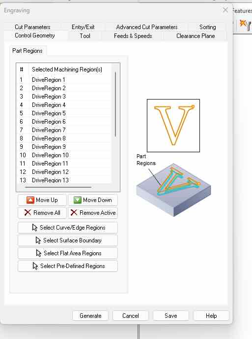
Select Geometry
Begin each machining operation in the Select Geometry tab.
- Right-click the desired layer.
- Choose Select All Objects.
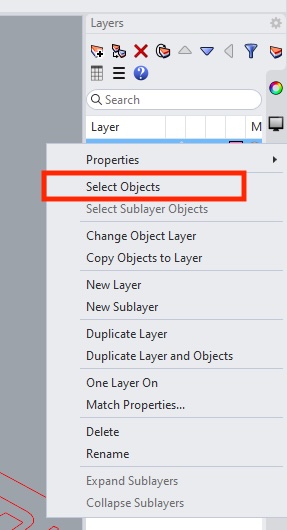
The selected geometry will appear in the operation window.
Select the Tool
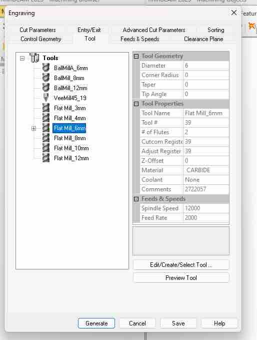
Choose an existing tool from the library or create a new tool matching the cutter being used.
Specify the cutter diameter and any required machining parameters.
Feed Speed
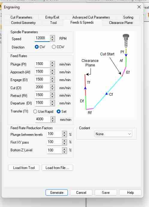
Specify the cutting feed rate appropriate for the selected tool and material.
Clearance Height
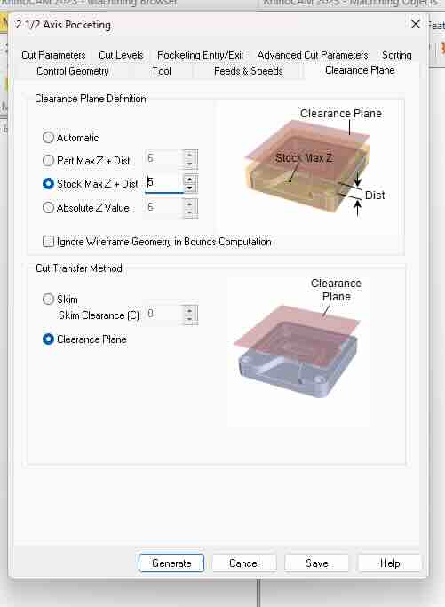
Set the clearance height to ensure the cutter safely clears the workpiece while moving between cuts.
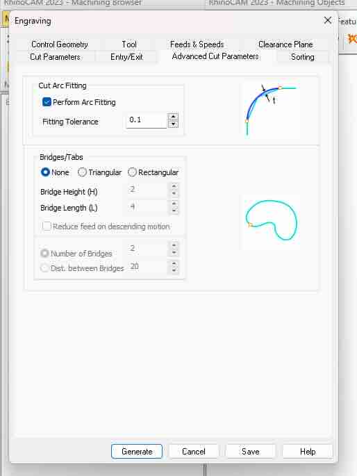
Bridges (Tabs)
Bridges are critical when machining small components or parts requiring a clean finish.
They intentionally leave small sections of material uncut, preventing parts from moving before the machining operation is complete.
Without bridges, loose parts may:
- Shift during machining
- Damage the cutter
- Ruin the workpiece
Start Point
In many cases the tool start point is not critical.
However, for visible surfaces it is often worth adjusting the entry point to minimize witness marks or tool entry scars.
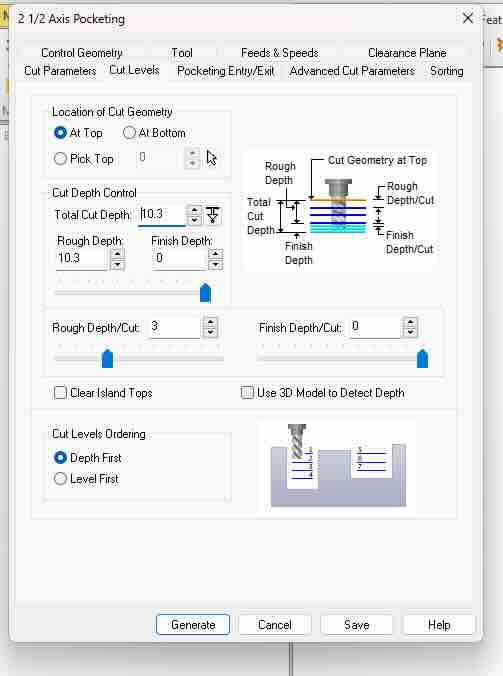
Cut Depth
The total cutting depth should match (or be slightly greater than) the thickness of the stock material.
For each machining pass:
- Remove no more than approximately half the cutter diameter.
This reduces tool loading and produces cleaner cuts.
CAM Settings by Layer
After configuring each machining operation, generate and review the simulated toolpath before exporting the G-code.
Simulation is an important step for identifying missing geometry, incorrect cut directions, or collisions before machining.
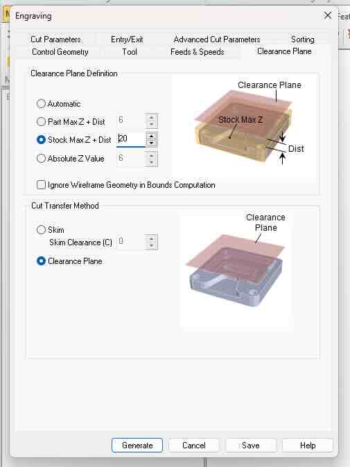
Engraving / Screw Marks
- Enable Show Path to verify the toolpath.
- Screw holes should only be deep enough to mark the material (approximately 3 mm).
- Set:
- Clearance Height = 20 mm
- The material has not yet been screwed to the bed.
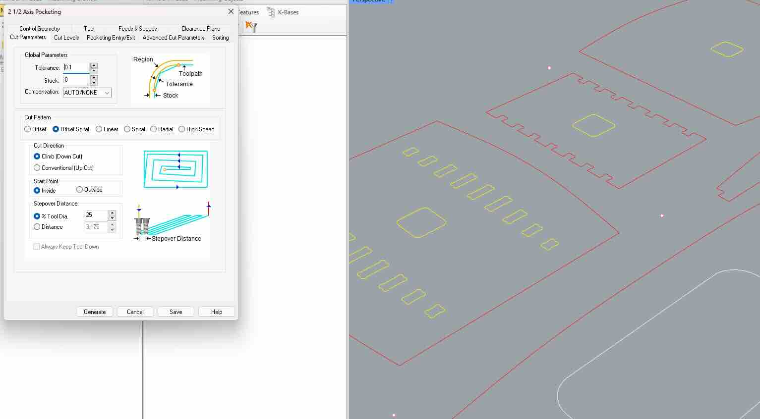
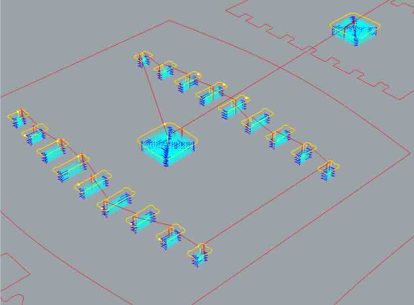
Pocketing
Before creating the operation:
- Clear any previous geometry selections.
- Right-click the appropriate layer and select all objects.
Recommended settings:
- Clearance = 5 mm
- Stock = 0 mm
- Cut Direction = Climb or Conventional
- Avoid Mixed
- Start Position = Inside
- Cut Level Ordering:
- Depth First
- Completes each pocket before moving to the next.
Internal Profiling
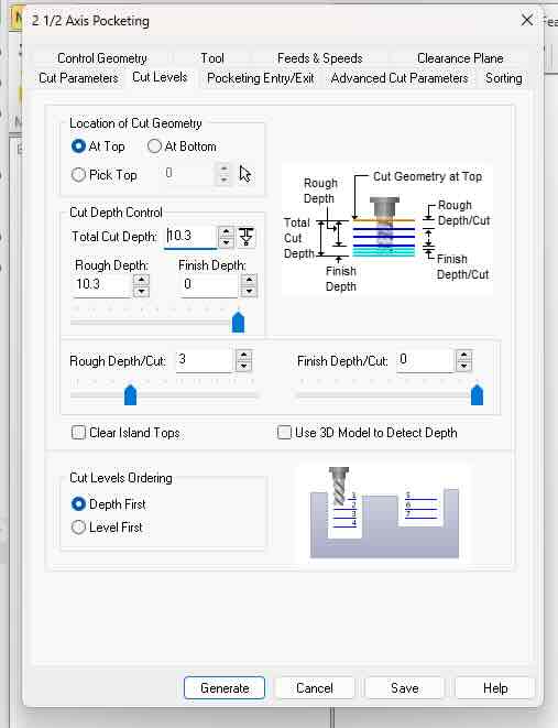
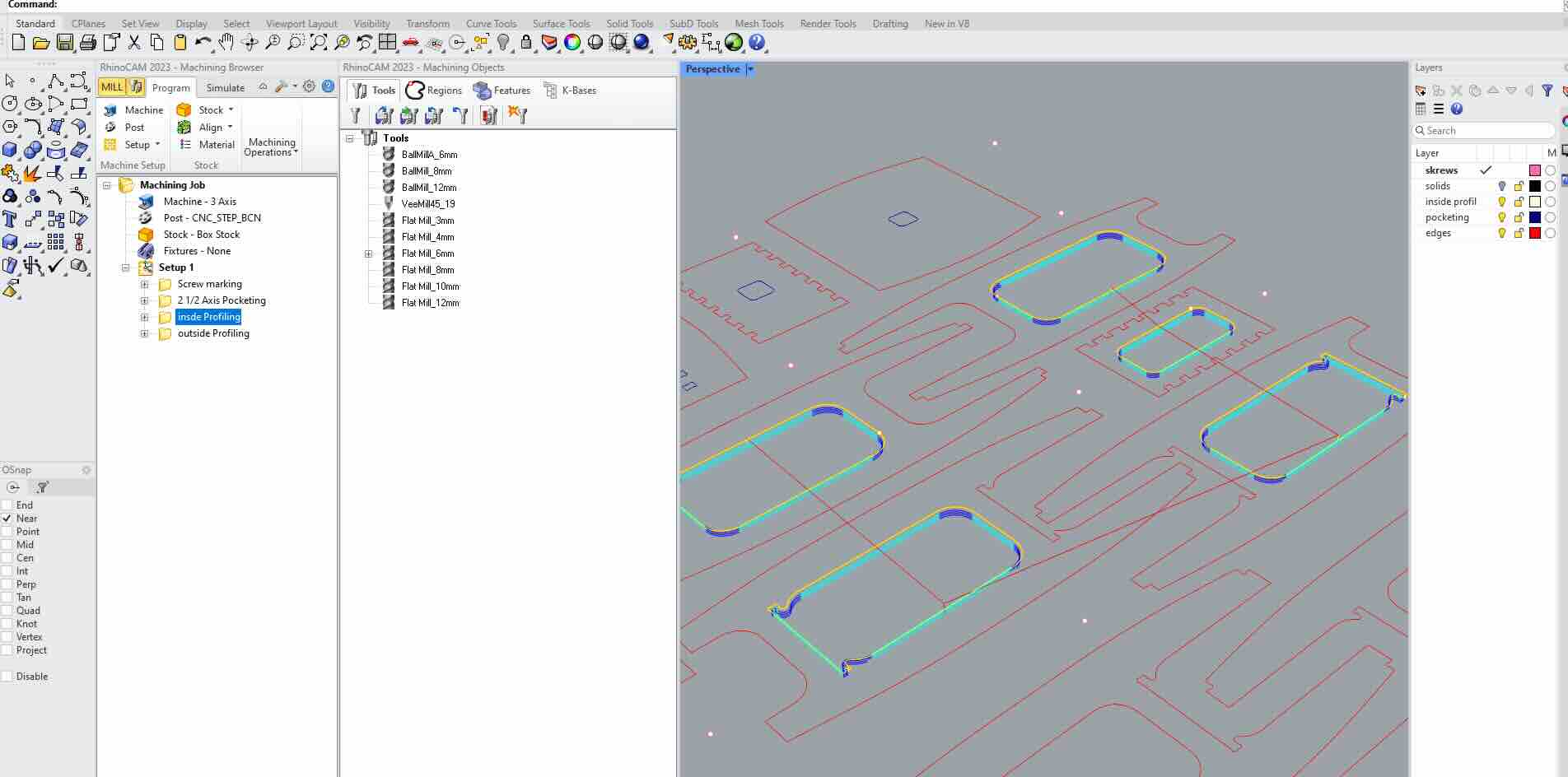
Recommended settings:
- Cut Direction = Single direction
- Cutting Side = Inside
- Total Cut Depth = 10.3 mm
- Pass Depth = 3 mm
- Entry / Exit = None
Tabs
- Shape = Rectangular
- Height = 3 mm
- Length = 4 mm
Finally, verify that the toolpath is located inside the profile.
External Profiling
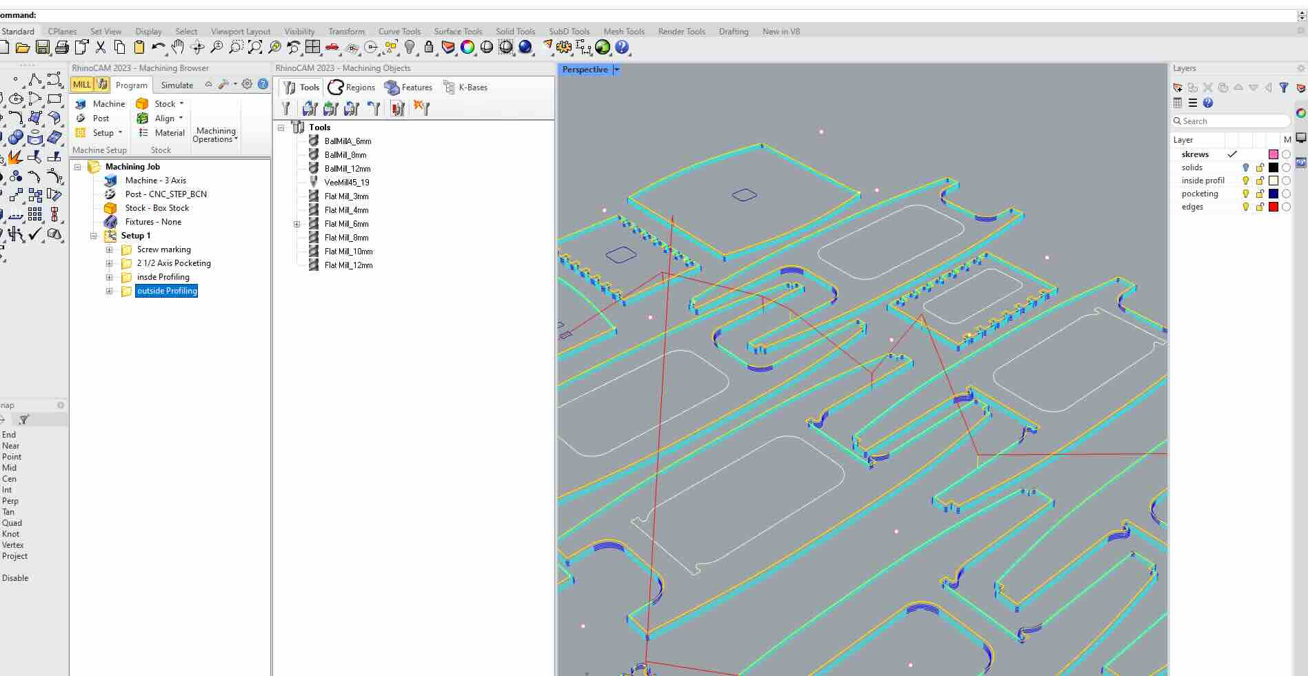
- Select all geometry on the external profile layer.
- Verify that the correct number of objects has been selected.
- Set:
- Cutting Side = Outside
Tabs
- Start with 4 tabs per component.
- Inspect each part to ensure it remains securely attached.
- Increase the number of tabs for large or irregularly shaped parts if necessary.
Exporting the Toolpaths
Once all machining operations have been verified:
- Post-process the Screw Hole operation separately.
- This allows machining to pause so the stock material can be secured to the machine bed.
- Select the remaining operations.
- Verify they are ordered correctly.
- Post-process them together into a single machining file.
- Before saving, confirm that the correct CNC machine post-processor has been selected.
Cutting the Parts
Step 1: Attaching the Material
Begin by securing the stock material to the CNC machine.
- Open the Engraving (Screw Holes) machining file on the CNC computer.
- Place the stock material on the machine bed.
- Align the material as square as possible with the edge of the machine table.
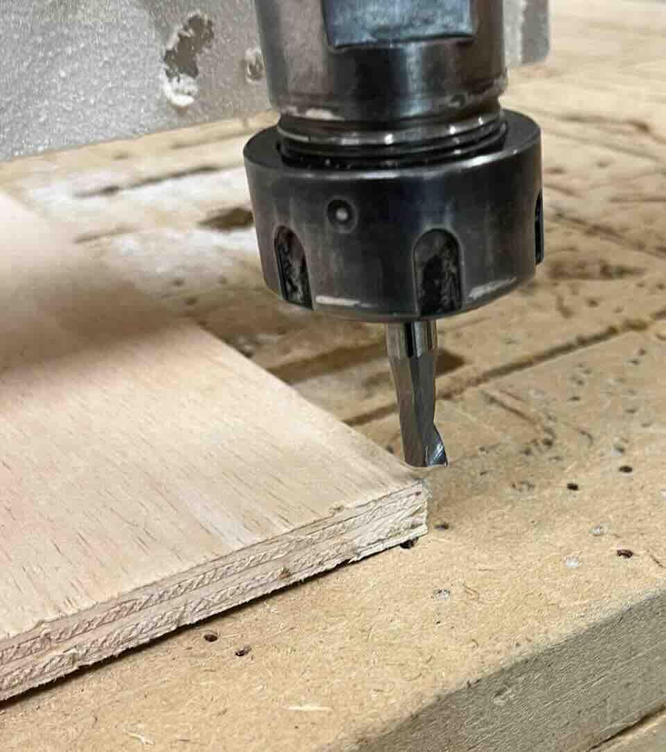
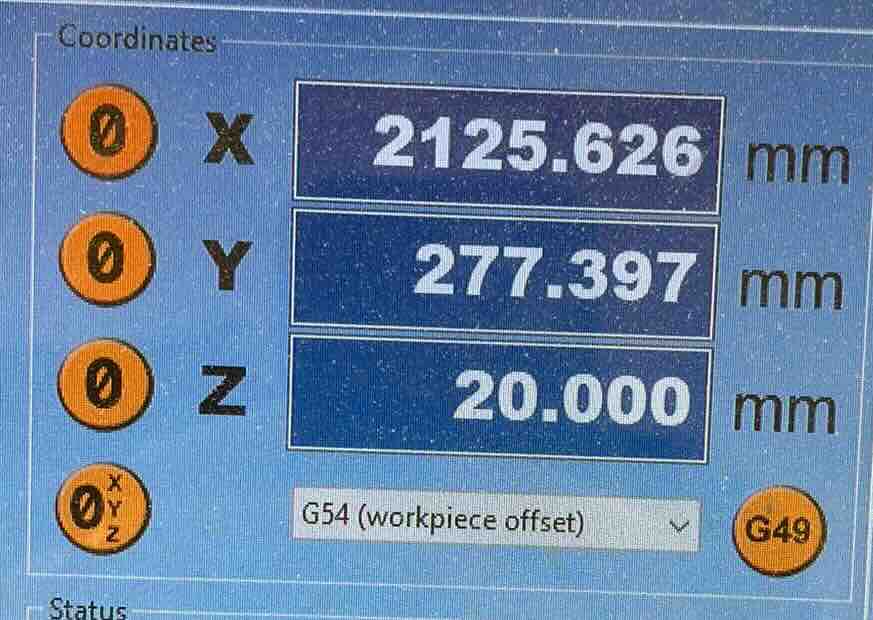
Set the X and Y Zero
- Move the cutting tool to one corner of the stock material.
- Zero the machine in X and Y.
- X corresponds to the long axis of the table.
- Y corresponds to the short axis.
Set the Z Zero
- Move the cutter a small distance inside the corner of the stock.
- Slowly lower the cutter until it just touches the surface of the material.
- Set the Z-axis to zero.
Verify the Toolpath
Before machining:
- Plot the toolpath.
- Jog the machine around the perimeter of the job.
- Verify that the complete toolpath fits within the stock material.
Mark the Screw Locations
Run the engraving file to mark the screw locations.
Once complete:
- Move the spindle safely away from the workpiece.
- Secure the stock material using screws.
Step 2: Cutting the Design
After the material has been screwed down:
- Re-zero the Z-axis.
- Tightening the material can slightly change its height.
- Load the next machining file.
- Begin machining the remaining toolpaths.
Step 3: Removing the Parts
Before removing any material:
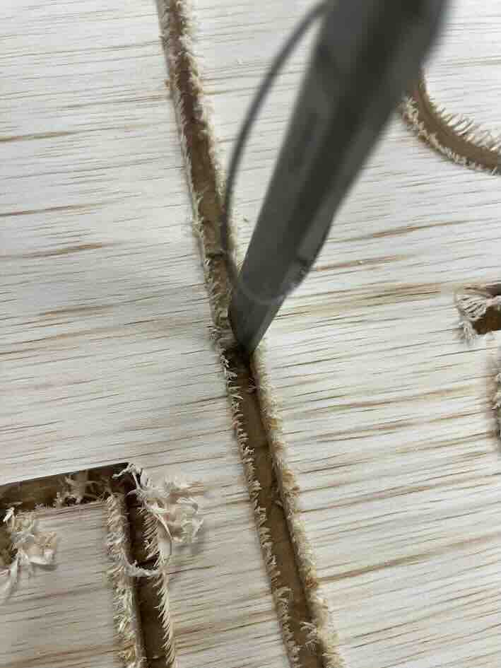
- Confirm that every profile has been cut completely through.
- Inspect the bridges (tabs) to ensure they are the only remaining connections.
Once verified:
- Remove all screws.
- Use a chisel to break the bridges.
- Remove the finished parts from the stock material.
Issues Encountered
During machining, several issues were encountered that required troubleshooting.
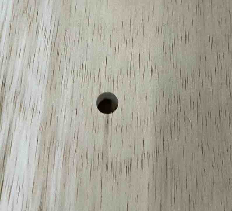
1. Screw Holes Were Cut Too Deep
Problem
The screw holes were significantly deeper than intended.
Cause
- Unknown.
Solution
- Edited the generated machining script using Find and Replace to correct the cutting depth.
2. Parts Were Not Fully Cut Through
Problem
Several parts remained attached because the cutter did not completely penetrate the stock material.
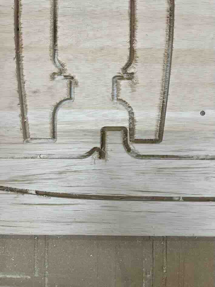
Cause
- Forgot to re-zero the Z-axis after screwing the material to the machine bed.
Solution
- Re-zeroed the Z-axis.
- Re-ran the machining program.
Although increasing the machine speed to 150% reduced machining time slightly, much of the second run simply retraced existing toolpaths without removing additional material.
3. One Part Came Loose During Machining
Problem
One component detached from the stock before machining was complete.
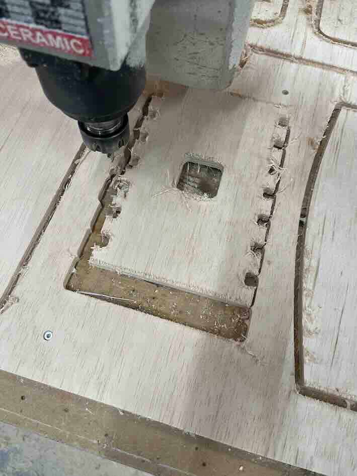
Cause
- No bridges (tabs) had been added to that part.
Solution
- Carefully verify bridge placement during CAM setup.
- Ensure every part is secured by either:
- Tabs, or
- Screws.
Post Processing
Post processing can be just as time-consuming as the design and machining stages.
The amount of finishing required is heavily influenced by:
- Quality of the CAD model
- CAM settings
- Material properties
- Cutter selection
In this project, the stock material was very soft, resulting in several imperfections that required additional cleanup.
Cleaning the Edges
The machined edges were rough and required extensive sanding.
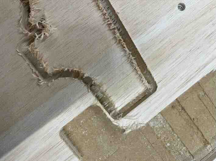
Gluing the Assembly
Because the material was very soft, the edges degraded during machining.
As a result:
- The joints became loose.
- Additional glue was required during assembly.
In retrospect, producing a small test piece before machining the final parts would have helped verify the joint tolerances.
To maintain accurate right angles during assembly:
- Squares were clamped to both sides of the workpiece.
- The components were glued while resting against the reference surfaces.
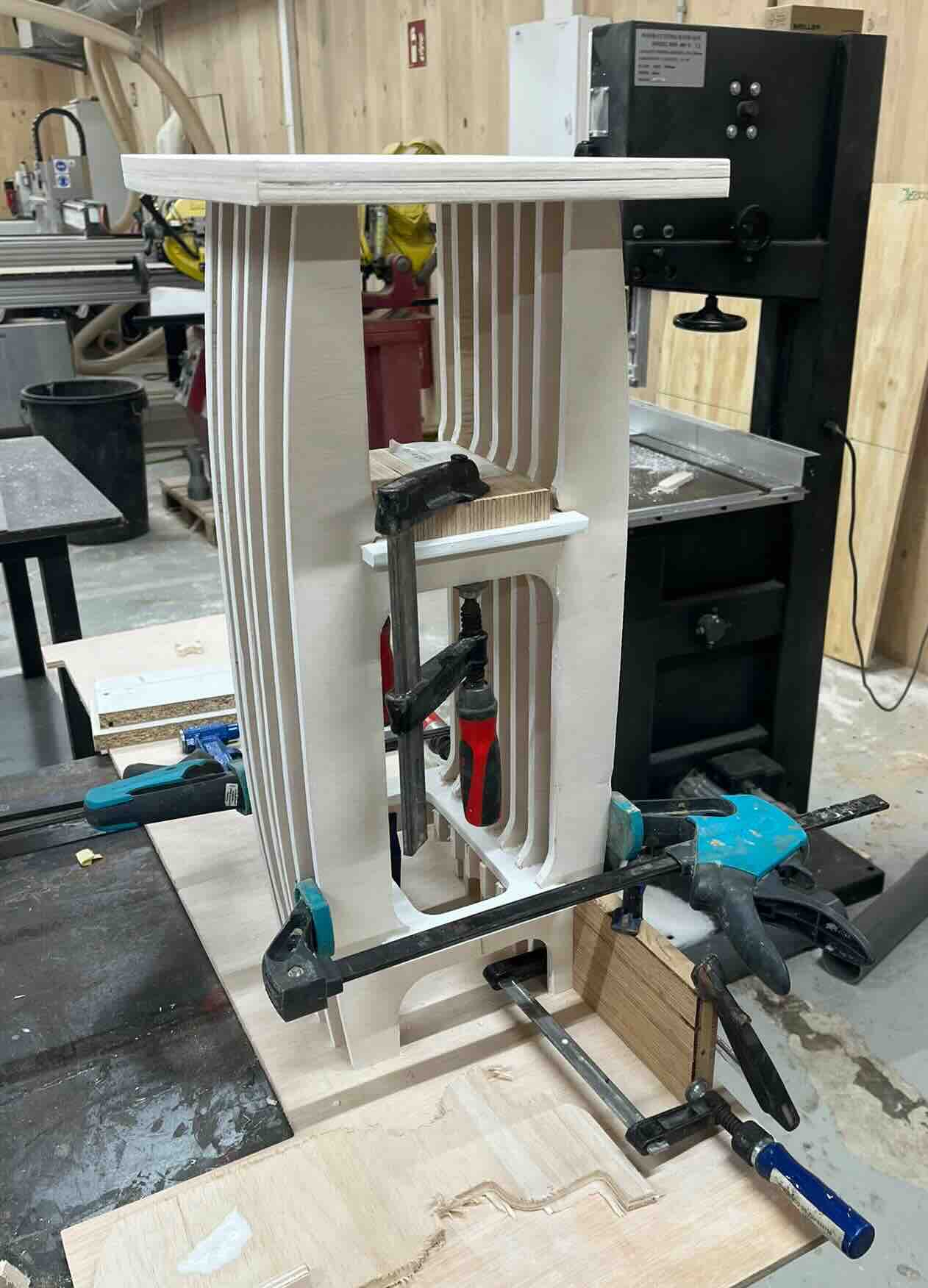
Final Result
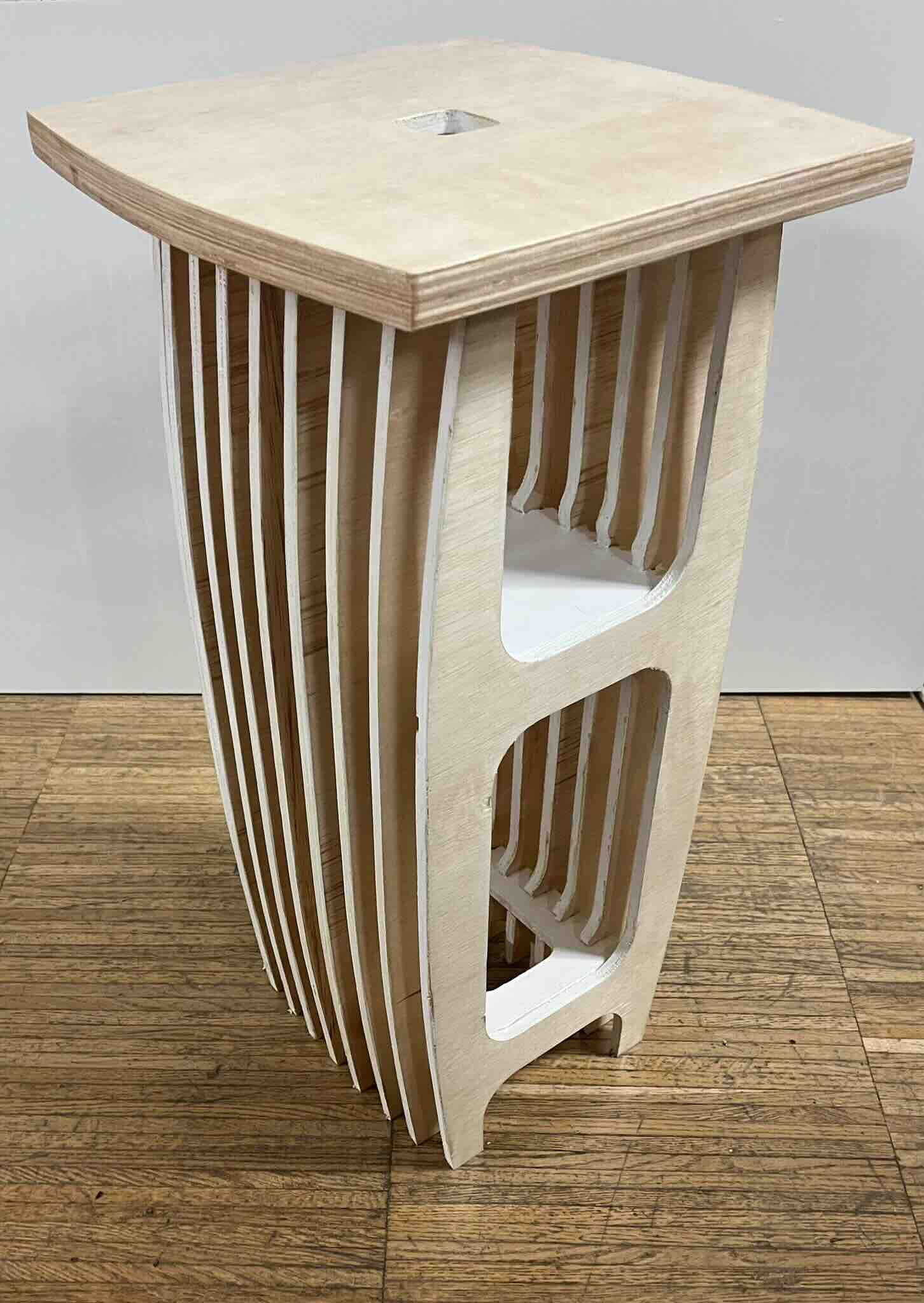
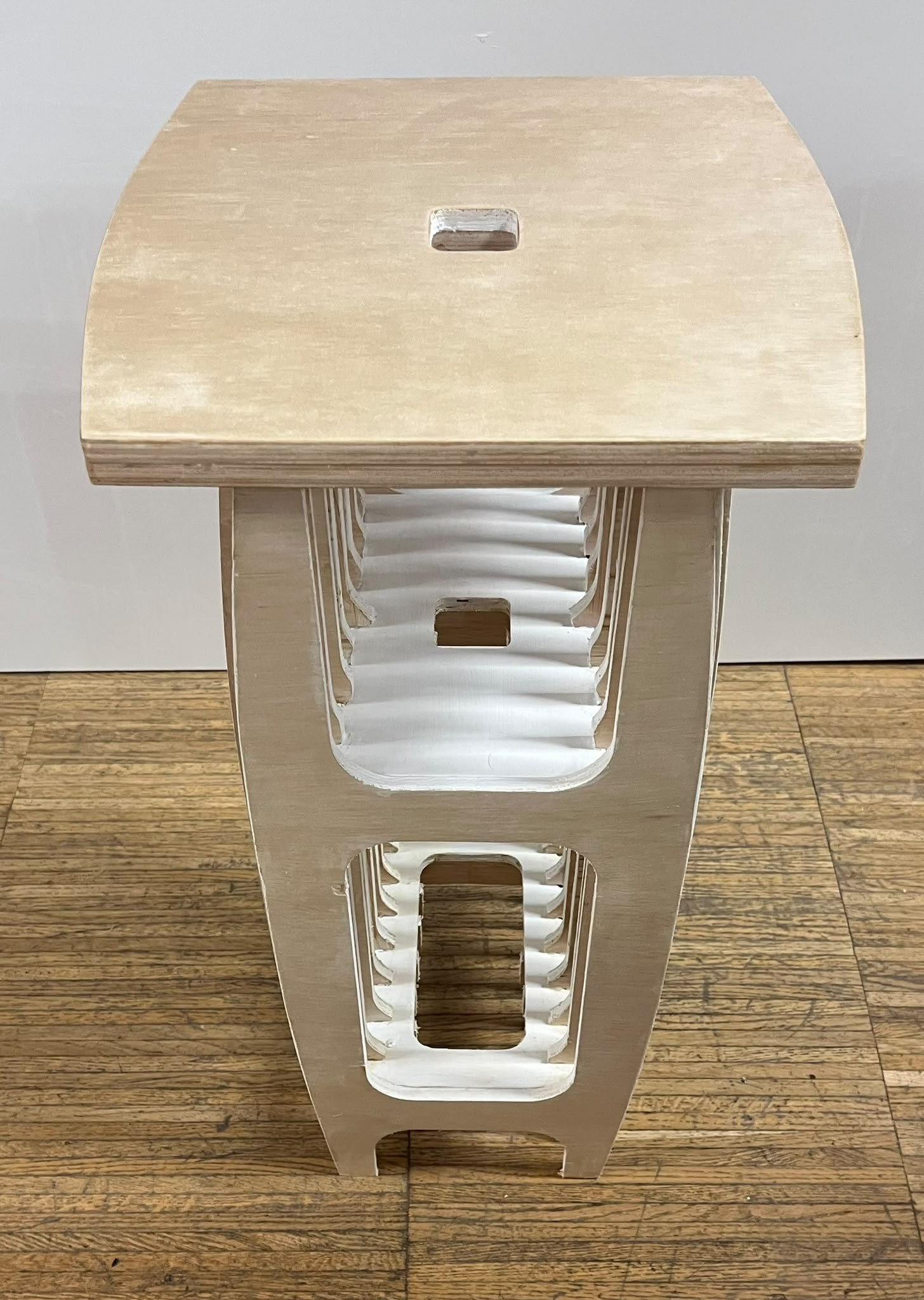
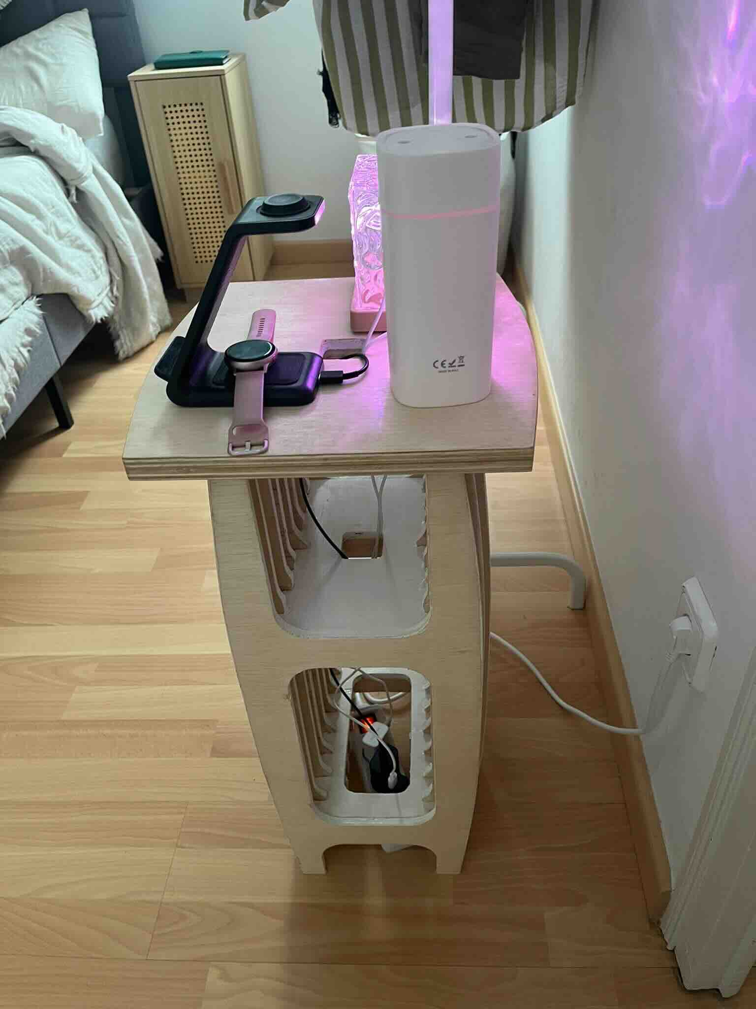
Although the final product was not as clean as intended, it successfully demonstrated the complete CNC workflow from CAD through fabrication and assembly.
The project also provided valuable experience in:
- CAD preparation
- CAM setup
- CNC machining
- Work holding
- Assembly
- Troubleshooting