Fusion documentation
Fusion Intro
Autodesk Fusion is a cloud-based 3D modeling, CAD, CAM, CAE, PCB, and data mangement software platform for product design and manufacturing.
-
Design and engineer products how you want to ensure aesthetics, form, fit and function
-
Engineer, design and create anything with comprehensive electronics and PCB design tools
-
Save time and money and get quality parts out the door faster
Useful tutorials
Lego Example: - How to 3D Model a Lego Brick
In class Lego Example - Friday, Jan 30th: - CAD with Fusion Password: PJyNd4w*
Fusion Example: Rocking Chair
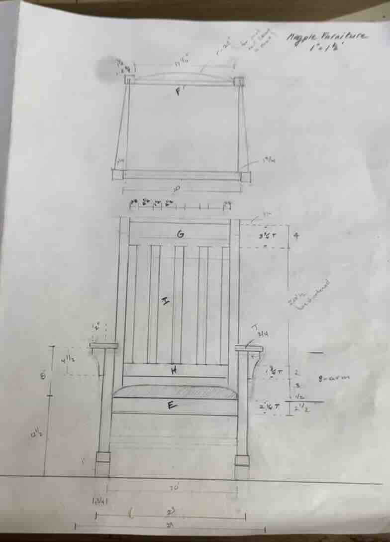
As an introduction to Fusion I worked through modeling of a rocking chair. I designed and built this chair last year so I am very familiar with all aspects of the design. I was particularly interested in modeling this design becuase there were many manual steps that could be automated using CAM cutting tools. Automation of these steps would greatly reduce construction time and improve profitability of the process.
Click to download Rocking chair design file
Steps
- create a construction plane
- this should be the plane you want to draw on.
- Creating parameters
- Option A: go to Modify —> change parameters click the plus sign to add parameters —> type name and associated dimention
- Option B: when drawing or creating a shape you can define the parameter in dimension box by typing
your variable name = value
- Draw sketches and extrude to create geometry
- see below for the various ways to build geometry
- As you go name bodys, construction planes, and sketches to keep the drawing organized
- When the geometry is complete, select bodies and convert to components
- Perform analyses
- Clash detection
- Create manufacturing drawings
Creating a sketch
- Click create sketch
- select the plane one which you want to draw
- define the shape by coordinates or by clicking and draging
- click on the constrain symbol this allows you to enter values or variable names for dimensions and define relationships between elements of your sketch
- when you are done click the green check in the upper left corner to finish sketch. Note: sketchs are just the 2D lines that you use to build your bodies and components. They are not attached to a body and can be used in generate more than one 3D geomentry.
Creating a body
- select the sketch that you would like to extrude, sweep, revolve exc.
- go to create and selct the appropriate function
- follow the instructions on the properties window that opens on the left
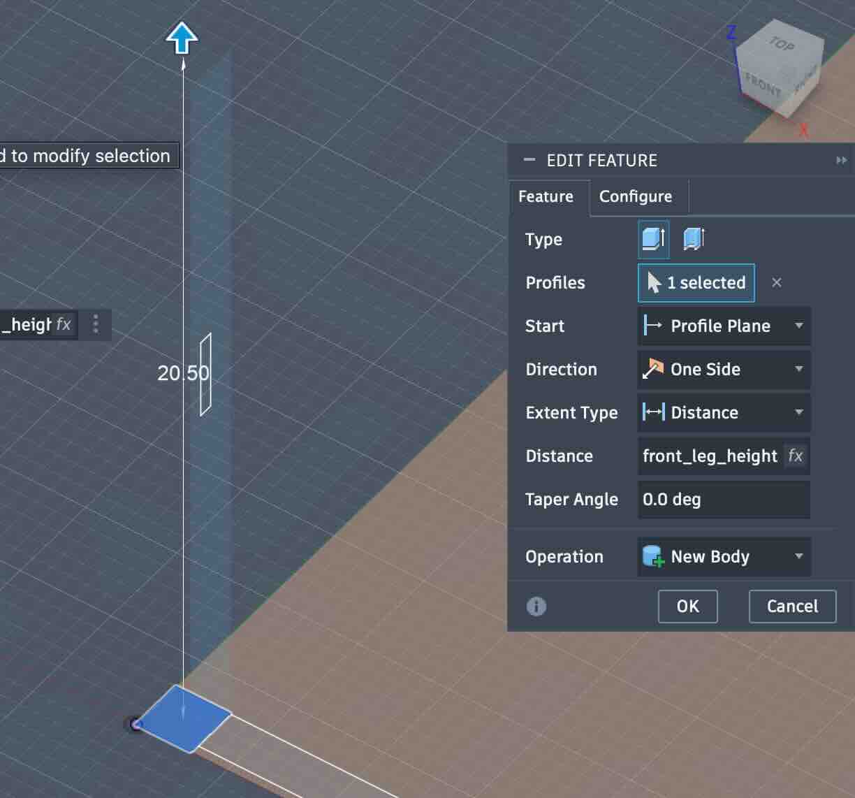
- In the example of an extrusion above you ensure a. ensure you have the correct profile selected, b. select the profile plane c. choose your direction d. select extend type e. specify a distance (in this case the distance is defined by a parameter) f. select the correct opperation
Note: that there are may default fields in place. typically these do not need to be modified but you should always check them. —— in the above example the operations field also allows to subtract or create a void. Although there will be a default it is very easy to miss checking this field and it will often not be the operation you intend.
To create another body make sure that you dont already have a body selected and start the process over.
Tip: It can be helpful to hide existing bodies and make sure the desired sketches are visible. This makes it easier to see what you are doing and avoid mistakes.
Shaping a body
- You can shape a body into more complex geometry using all of the modify funtions
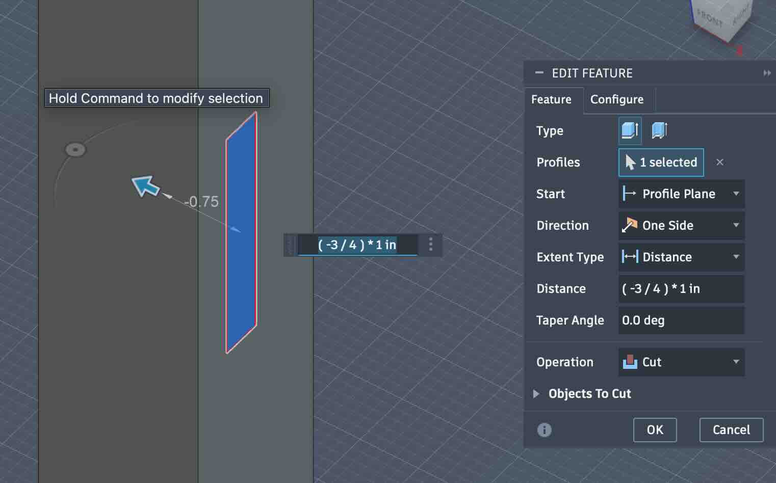
- You can also add to body by extruding additional features. To do this:
- first ensure you have sketch on the correct plane that you would like to add geometry
- select the body you would like to add to
- click extrude
- select the sketch you would like to extrude and follow the directions.
- 
- In the example above a void is being cut from the existing body. Note that the operation is cut. Note that in this case the distance is entered as a function. This simply makes the math easier.
Mirroring parts
- create a construction plane accross which you would like to mirror bodies. The center of what ever you are building is obviously recomended. you can drag the corner of the plane to make it an approprate size
- select the body you would like to mirror
- click the mirror function under create.
 - Autodesk Fusion (Education License).jpg)
Patterning parts within a given shape
-
using construction lines draw line from the center of your arc to the raidal point.
-
draw a box that perfectly fits your arc. the corner should be coincident with the end and the center of the box could be tangent to the center of the curve
-
draw lines from the radial point of the curve to the upper edge of the box you just drew. The number of lines should be equal to the number of elements you want to create.
-
These lines are now perpendicular to the arc at the point they intersect the arc. They can be used to draw the elements
Sketching the elements
- use your construction lines to draw the elements that you want to pattern.
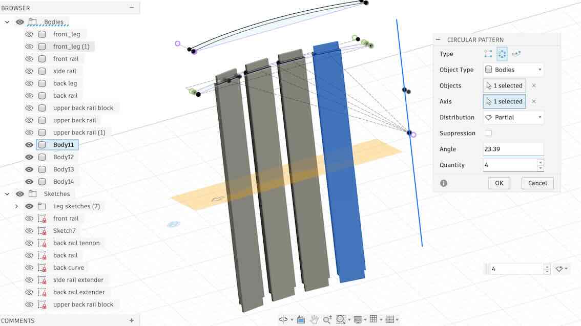
Solid paterning
-
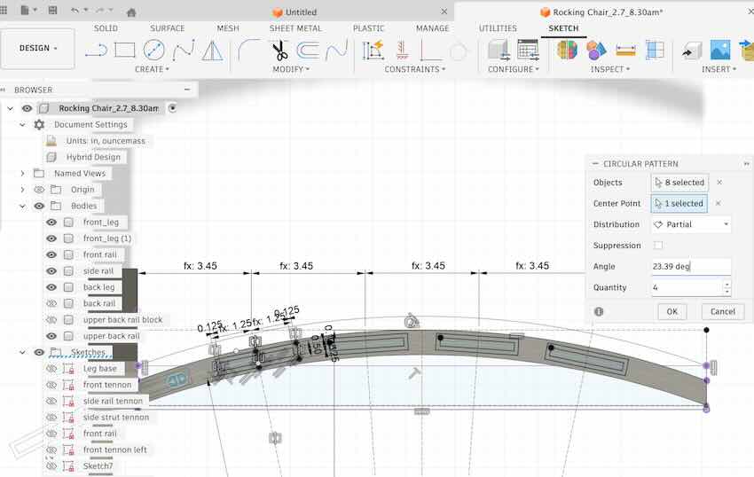
select the elements you want to patern and go to create —> circular pattern
- specify the number of elements, the centerpoint (the radial point that you created with construction drawings) and the angle over which you want them distribute the elements (you can find this by inspecting the angle between the outermost radial construct lines)
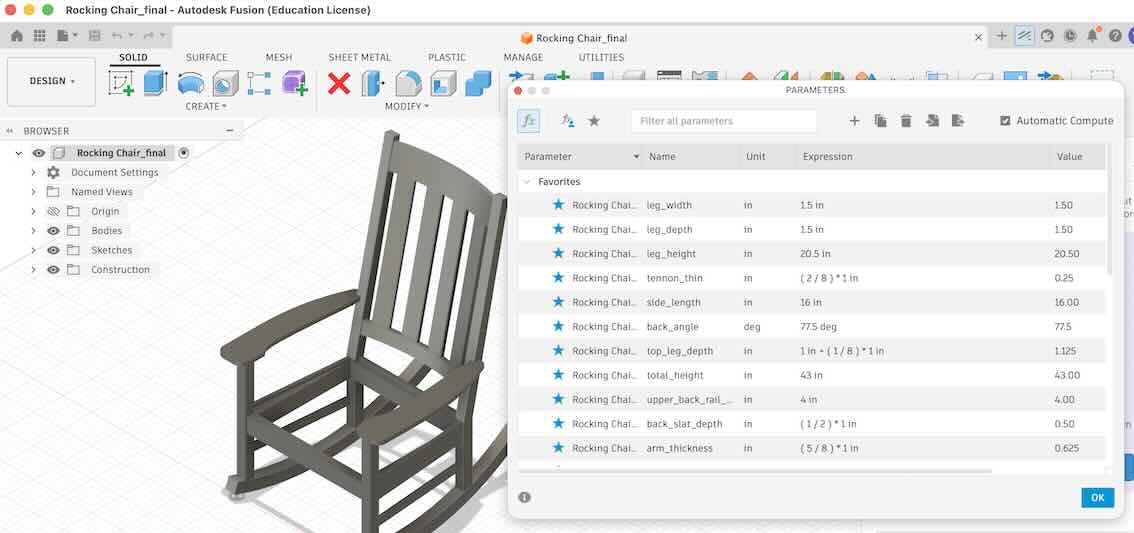
Parametric Design
There are two aspects of parametric design that are critical to working in fusion
- Define Parameters
- Option A: go to Modify —> change parameters click the plus sign to add parameters —> type name and associated dimention
- Option B: when drawing or creating a shape you can define the parameter in dimension box by typing
your variable name = value - Note that you can use other variables in your parameter definition
Following the rocking chair example, I used many modifiable parametres in the desing in order to easily modify the dimensions of the chair
- History tool
- The history tool shown along the bottom of the page allows you to go back in time and modify, update or delete steps that you did in the past. Everything that proceeds that step will then be updated relative to the change in proceeding steps.
Following the rocking chair example, you can see the history bar along the bottom of the window.
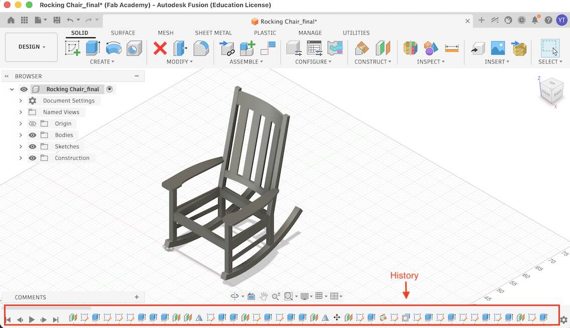
Pressing the play button on the right side of the bar allows you to visualize the history.
Preparing a Drawings for Cutting
For this example I will use a design for a wine rack constructed from equal thickness parts. This is a more practical design for computer controled cutting.
- Ensure that all bodies that you want to cut are converted to components
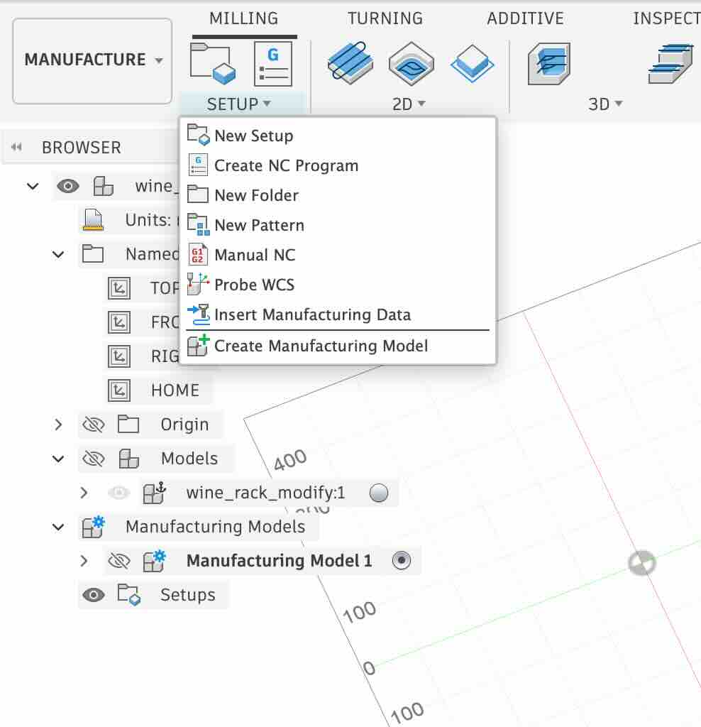
- In the upper left corner change the workspace to “Manufactuing”
- go to the setup menu and “Create Manufacturing Model”
- Right click on the newly created manufacturing model to edit
- This allows you to edit only the manufacturing model without editing the design model model.
- Go to Modify —> Arrange
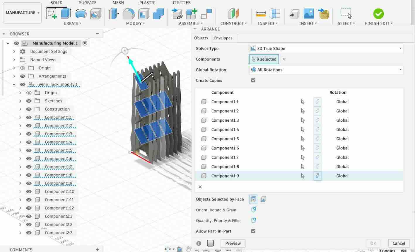
- Select the components you want to arrange in your 2D layout
- It is helpful to un-check the preview if you have many pieces to select
- Specify the size of the stock material
- you can now check the preview to make sure everything looks ok

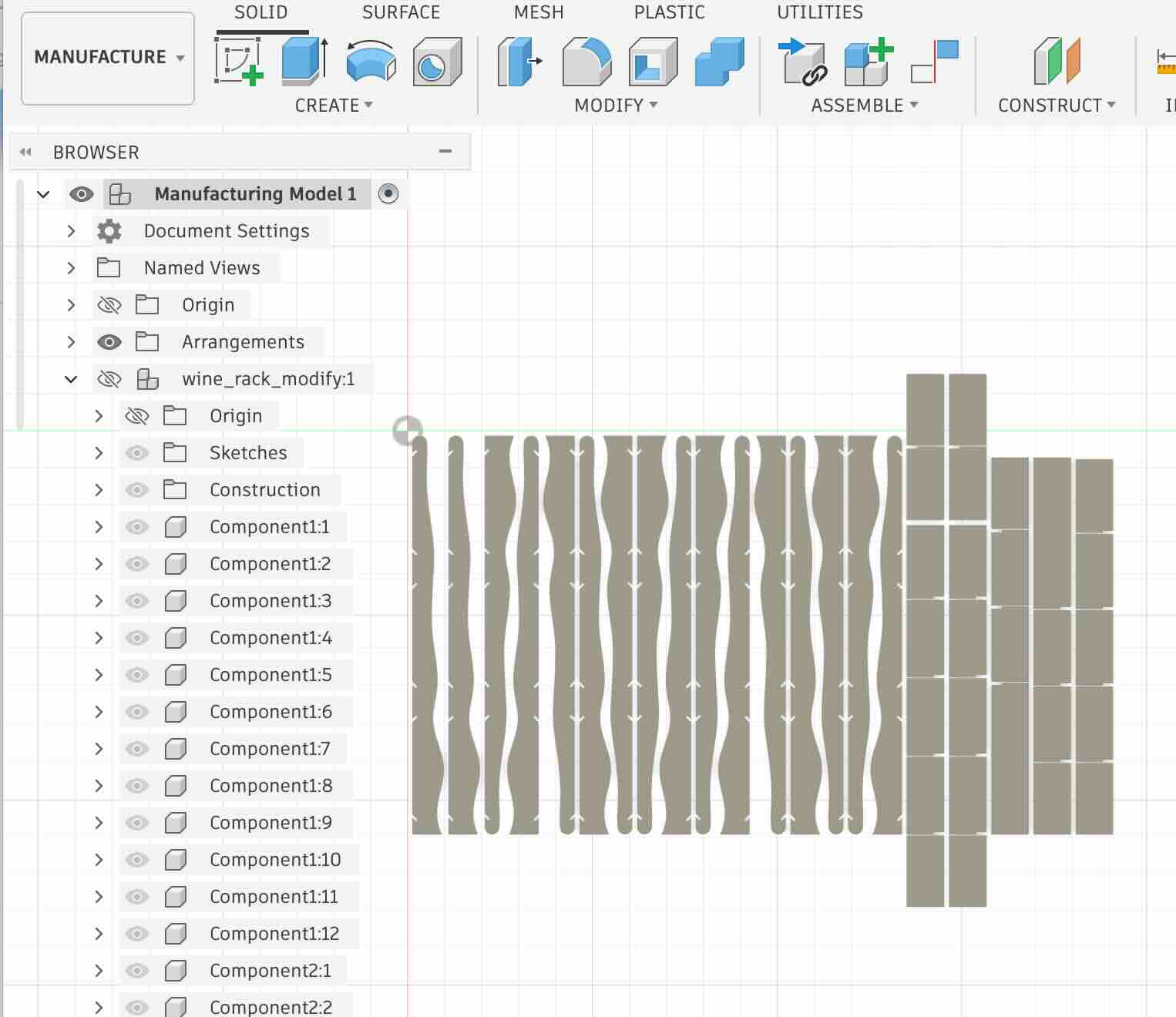
- you can now check the preview to make sure everything looks ok