Rhino and Grasshopper
Basic Rhino Workflow
1. Create Reference Geometry
Before creating solid forms, begin by sketching the basic geometry in 2D. Usually this is done in the Top View viewport.
Drawing Initial Geometry
-
Use the
Linecommand to draw the first component. -
Start at a known coordinate such as
0,0. -
Type exact distances or coordinates into the command line for precision.
Example:
-
Start line at
0,0 -
Type
100,0to create a 100 mm horizontal line.
Creating Reference Construction
Use the first geometry to construct the rest of the sketch.
Useful commands:
-
Line -
Polyline -
Offset -
Copy -
Extend -
Trim
Tips: - Turn on Osnap to snap precisely to:
-
End points
-
Midpoints
-
Intersections
-
Centers
-
Use reference lines to locate:
-
holes
-
supports
-
mounting points
-
symmetrical features
-
Construction geometry can later be deleted or moved to a separate layer.
2. Creating Solid Forms
Once the sketch is complete, use it to build 3D geometry.
Primitive Shapes
Simple geometry can often be made using predefined solids:
-
Box -
Cylinder -
Sphere -
Cone
These commands usually ask for:
- Base point
- Size dimensions
- Height
Example:
-
Use
Box -
Select first corner
-
Type dimensions
-
Enter height
Create Custom Geometry
More complicated forms usually follow this workflow:
- Draw a 2D profile or surface
- Convert the sketch into a surface if needed
- Extrude the geometry into 3D
I will work through the same example of custom geometry as the fusion turoial - working through the CAD of a simple rocking chair
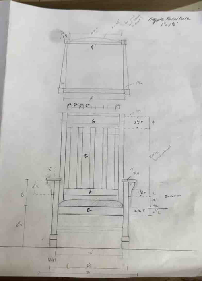
Click to download Rocking chair design file
Draw inital geometry using sketches
-
use coordinates to draw the dimensions of the first leg starting from 0,0
-
refrencing the first leg use lines to create reference points in order to draw the remaining components to the correct dimensions
Create solid forms
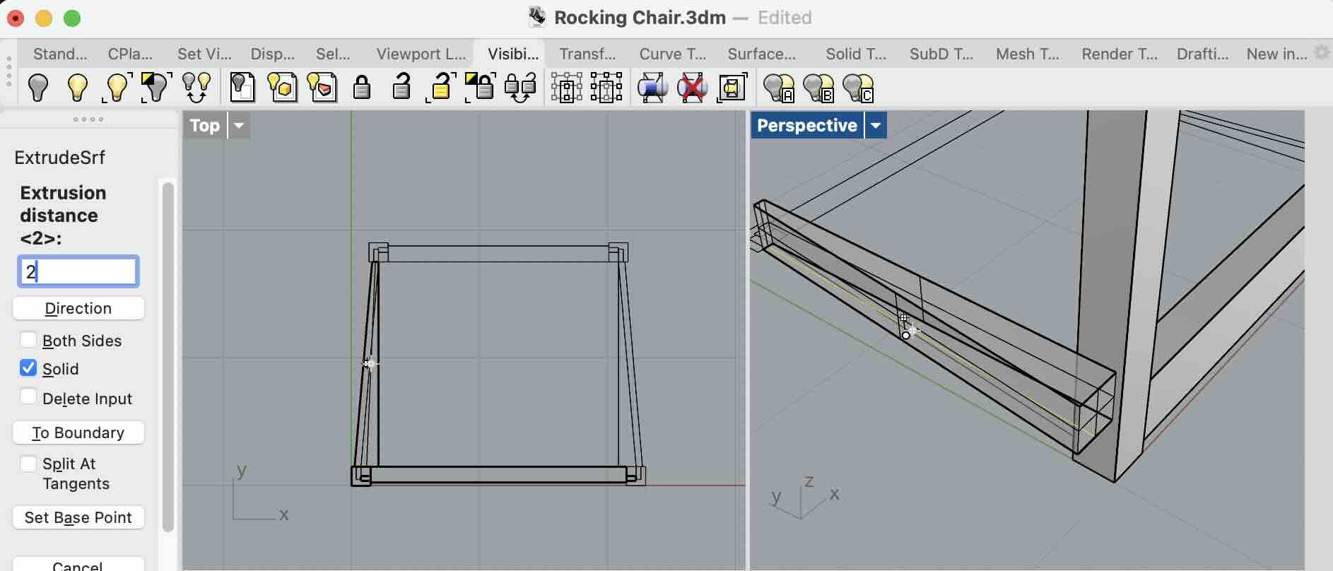
Extruding Curves
Use:
ExtrudeCrv
Process:
- Select closed curve
- Specify extrusion direction
- Enter height
Options:
-
Solid=Yescreates a closed solid body -
BothSides=Yesextrudes in both directions
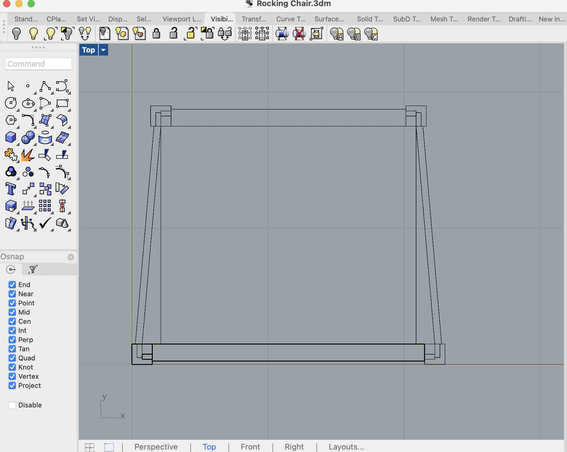
Extruding Surfaces
Use:
ExtrudeSrf
This is useful for:
-
sheet bodies
-
curved panels
-
more advanced shapes
For the chair example I used Extrude to pull select sketches into solid forms
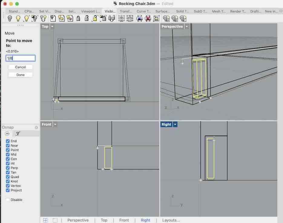
Using the Move Command
- Select object
- Type
Move - Choose a base point
- Choose direction or destination point
Tips:
-
Use the viewport that best matches the movement direction:
-
Top View → X/Y movement
-
Front View → vertical movement
-
Right View → depth movement
-
After beginning the move, type the exact distance into the command line.
Example:
-
Start moving object horizontally
-
Type
# you want -
Press Enter
-
Click the object to move and use command “move”
-
Click in the window with the best visiability for the direction you want to move the object. Once you start moving it in the correct direction, type the exact disctance into the left hand pannel.
-
Once the object is in the correct location, group it with other elements to maintain its realtive location
Using the Gumball Tool
The Gumball is often faster than the Move command.
Features:
-
Arrows move objects
-
Arcs rotate objects
-
Boxes scale objects
Tips:
-
Drag arrows to constrain movement to one axis
-
Hold
Altwhile dragging to create copies
Enable:
- Bottom toolbar →
Gumball
Organizing Geometry
Grouping Objects
Once parts are correctly positioned:
-
Select multiple objects
-
Type
Group
Benefits:
-
Maintains relative positioning
-
Easier selection
-
Simplifies assemblies
To edit:
Ungroup
Using Layers
Layers help organize complex models.
Typical layer structure:
-
Construction
-
Main Bodies
-
Hardware
-
Curves
-
Reference Geometry
Useful features:
-
hide layers
-
lock layers
-
color-code components
More ways to create geometry
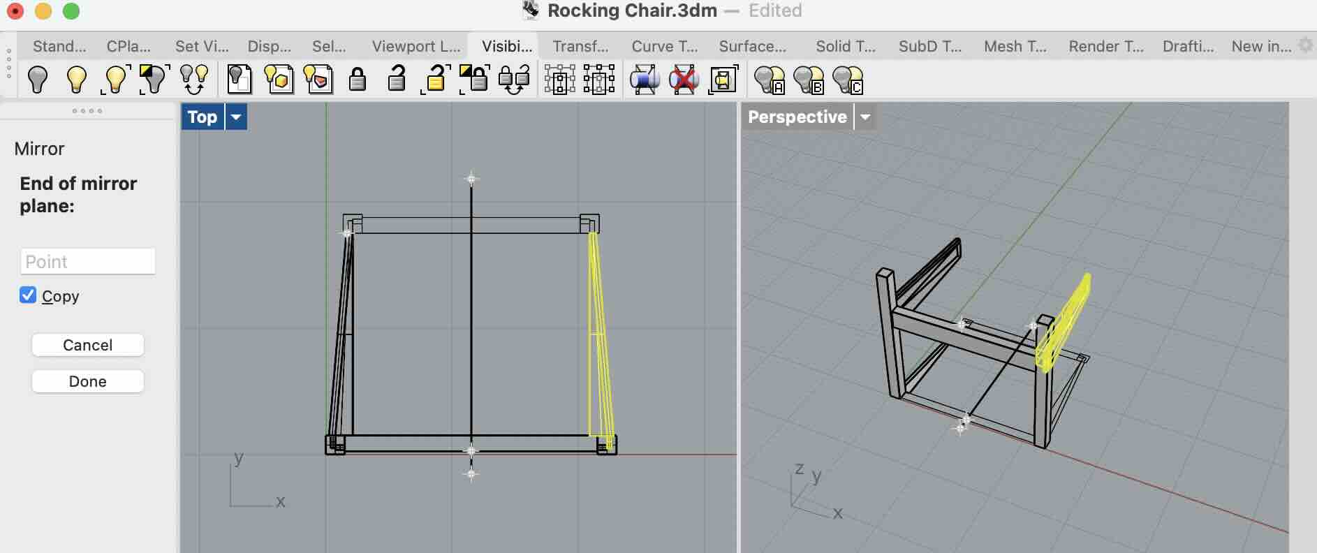
Mirroring Geometry
Mirror is useful for symmetrical parts.
- Select object
- Type
Mirror - Define mirror axis with two points
Tips:
-
Use Osnap for precise symmetry
-
Enable
Copy=Yesto keep original geometry
Common uses:
-
left/right components
-
vehicle bodies
-
furniture
-
mechanical assemblies
Example
Creating Curves
Start with clean curves.
Useful commands:
-
InterpCrv -
ControlPointCurve -
Arc -
Circle
InterpCrv
Creates curves that pass through selected points.
Good for:
-
organic forms
-
smooth transitions
Control Point Curve
Creates curves controlled by edit points.
Good for:
-
industrial design
-
controlled surfacing
Editing Curves
Use:
-
PointsOn -
Move -
Scale1D
Tips:
-
Fewer control points create smoother geometry
-
Avoid overly complex curves
Creating Surfaces from Curves
Loft
Use Loft to create surfaces between curves.
Process:
-
Select profile curves in order
-
Adjust loft settings
-
Create surface
Good for:
-
hulls
-
handles
-
ergonomic forms
Sweep
Use:
-
Sweep1 -
Sweep2
These create surfaces along rails.
Useful for:
-
pipes
-
trims
-
structural members
Example

Revolve
Use Revolve for rotational geometry.
Examples:
-
bottles
-
cups
-
wheels
-
lathed parts
Process:
-
Draw profile
-
Select revolve axis
-
Rotate profile around axis
Joining Surfaces into Solids
Once surfaces are complete:
- use
Join
Check if object becomes:
Closed Polysurface
This means Rhino recognizes it as a solid body.
Boolean Operations
Useful for combining or cutting geometry.
BooleanUnion
Combines solids together.
BooleanDifference
Cuts one solid from another.
BooleanIntersection
Keeps overlapping geometry only.
Tips:
-
Geometry must fully intersect
-
Closed solids work best
Navigation and View Control
Basic Navigation
Rotate View
- Right mouse button drag
Pan
- Shift + right mouse button
Zoom
- Mouse wheel
View Modes
Useful display modes:
-
Wireframe
-
Shaded
-
Rendered
-
Ghosted
Switch modes from viewport dropdown.
Helpful Modeling Habits
-
Build accurate curves first
-
Save versions frequently
-
Keep geometry organized
-
Name important layers
-
Use snaps consistently
-
Check tolerances before fabrication
-
Avoid unnecessary control points
-
Build large forms first, details later
Intro to Grasshopper
Grasshopper is Rhino’s visual scripting environment.
Instead of drawing manually:
-
nodes perform operations
-
wires connect data flow
Grasshopper is useful for:
-
parametric design
-
repetitive geometry
-
generative structures
-
patterning
-
optimization
Basic workflow:
-
Create parameters
-
Connect operations
-
Generate geometry dynamically
Changes automatically update the model.