Week 11 — Networking and communications
Global Class
This week focused on how devices communicate across different scales, from chip-level connections to distributed network systems.
The concept of a “society of things” was introduced, where devices interact within layered infrastructures:
- chip-to-chip communication
- device-to-device communication
- large-scale networked systems
The session emphasized the shift from isolated electronic components to interconnected and modular systems.
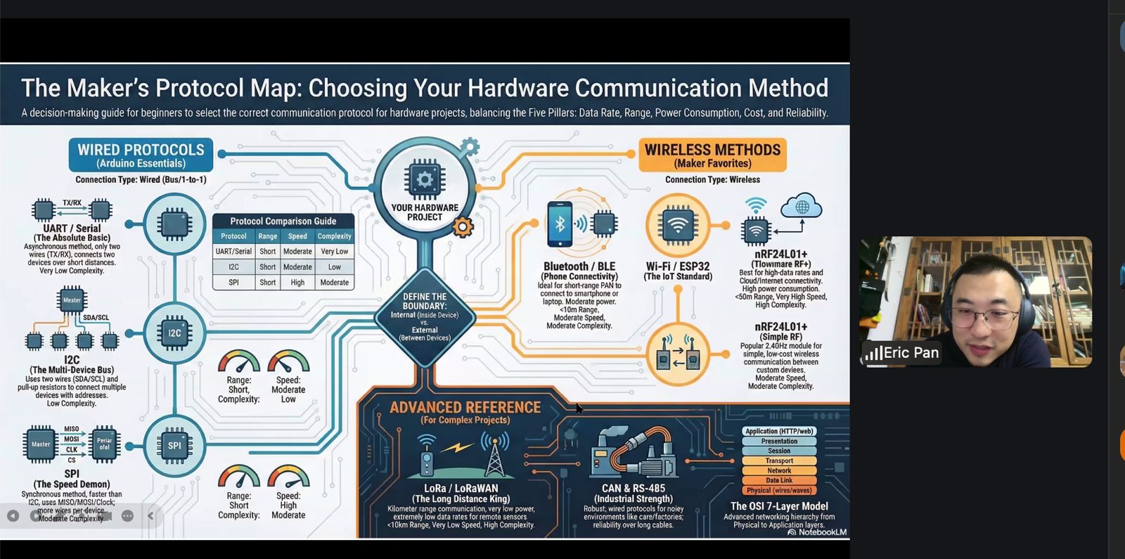
Eric Pan — Architectures of Digital Dialogue
Eric Pan presented a structured overview of communication systems, framing networking as a layered and scalable architecture.
1. The OSI Model
Communication is organized into layers, from physical signals to application-level protocols.
- Physical → electrical signals (voltage, frequency)
- Data Link → local communication rules (MAC)
- Network → addressing and routing (IP)
- Transport → reliability and delivery (TCP vs UDP)
- Application → protocols such as HTTP and MQTT
Key idea:
- each layer operates independently
- systems can evolve without affecting the entire stack
2. Wired Communication — Core Protocols
UART (Asynchronous)
- TX / RX communication
- no clock signal
- requires predefined baud rate
- used for debugging and simple point-to-point links
I2C (Bus Communication)
- 2 wires: SDA (data), SCL (clock)
- multiple devices on the same bus
- devices identified by address
- requires pull-up resistors
SPI (High-Speed Communication)
- multiple lines (clock, data in/out, chip select)
- high-speed communication
- point-to-point architecture
- used for memory, displays, and fast peripherals
Key insight:
- protocol selection depends on speed, topology, and number of devices
3. Wireless Communication
Wireless communication involves balancing key parameters:
- range
- power consumption
- data rate
- signal robustness
Key principle:
- longer range → lower data rate
- higher speed → shorter range
Examples:
- Bluetooth (BLE) → short range, low power
- Wi-Fi → high throughput, higher power consumption
- LoRa → long range, low power, low data rate
4. Network Architecture — System Design
Communication systems can be structured as:
- centralized systems (cloud-based)
- decentralized systems (edge computing)
Devices must:
- agree on communication protocols
- synchronize timing
- define roles (client/server or peer-to-peer)
5. Designing a Network
Effective communication design requires:
- selecting the appropriate abstraction layer
- choosing suitable protocols
- managing timing and synchronization
- ensuring reliable data exchange
Local Class
The local session focused on practical implementation of communication between microcontrollers.
The objective was to understand how two devices can exchange data using serial communication, and how this interaction can be tested both in simulation and with real hardware.
Reference System — Smart Citizen Platform
As reference system, the Smart Citizen device from IaaC was again presented showing a real-life implementation of a networked devices.
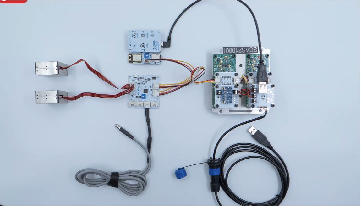
The system integrates:
- multiple sensors
- communication modules
- data aggregation and transmission
Concept — Network Representation
A visual representation of distributed nodes was introduced to explain how multiple devices interact within a network.
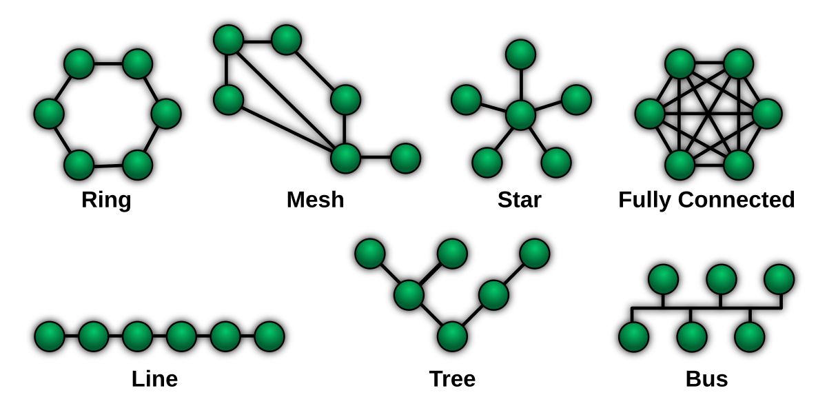
Each node represents a device capable of sending and receiving data, illustrating:
- distributed communication
- modular system design
- scalability of connected devices
Simulation — Wokwi Environment
A first test was performed using Wokwi to simulate communication between two devices.
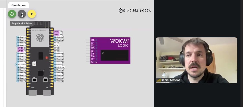
The simulation included:
- two microcontroller instances
- UART communication (TX/RX) between devices
- monitoring of transmitted values using a logic analyzer
This allowed quick validation of:
- signal flow
- data transmission behavior
- debugging without hardware constraints
Hardware Implementation — Device-to-Device Communication
The simulation was then translated into a physical setup using two development boards.
Setup:
- two microcontroller boards connected via UART
- TX of one board connected to RX of the other
- common GND shared between both devices
- USB used for power and programming
This configuration enabled:
- real-time data exchange
- verification of communication reliability
- comparison with simulated behavior
Group Assignment
Here is the work we did for the group assignment:
Learnings & Reflections
- Communication between devices requires shared protocols and correct physical connections such as common ground.
- UART provides a simple method for device-to-device communication using TX and RX lines.
- Simulation tools help validate communication logic before implementing hardware connections.
- Reliable data exchange depends on correct timing, wiring, and configuration of communication parameters.
- Understanding different protocols (UART, I2C, SPI) helps in selecting the appropriate method for each system.
- Reinforced the idea that complex systems are built from multiple interconnected components exchanging data.
Weekly Assignment
Dishwasher Reverse Engineering — System Breakdown
This teardown started from a practical situation: my dishwasher stopped working properly and began throwing multiple error codes.
The machine is a Bosch SM58M78EU (~2010), so already around 15 years old.
Reported errors
-
E09 → heating failure
Likely caused by a burnt or open-circuit heater inside the heat pump.
Standard fix: replace full heat pump assembly (not designed to be repaired) -
E15 → leak detected
Water in the base tray triggered the safety system
Likely due to internal leakage -
E23 → drain pump fault
Possible blockage or failing drain pump
Decision
At this stage, the situation was that the machine technically repairable, but multiple components failing and replacement parts required -heat pump, possibly pump, seals- which didn’t justify the cost for a 15-year-old machine
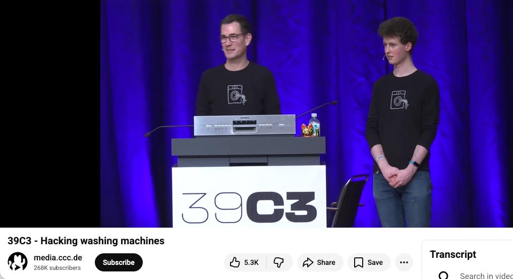
What started as a failed repair turned into a reverse engineering exercise, inspired by the global class link on hacking machines:
The goal was to understand how a real-world, mass produced system is engineered and built:
- opening a complete product
- identifying subsystems
- tracing connections
- understanding how everything communicates
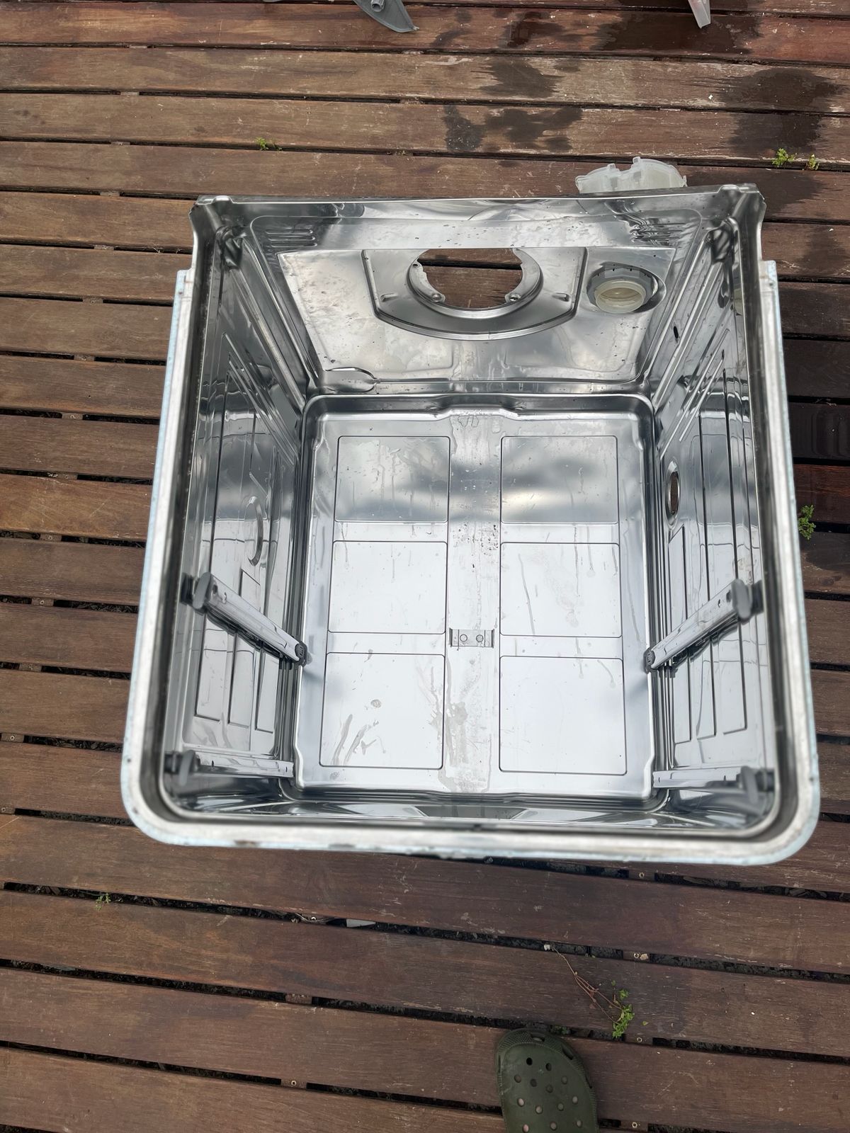
Full Teardown
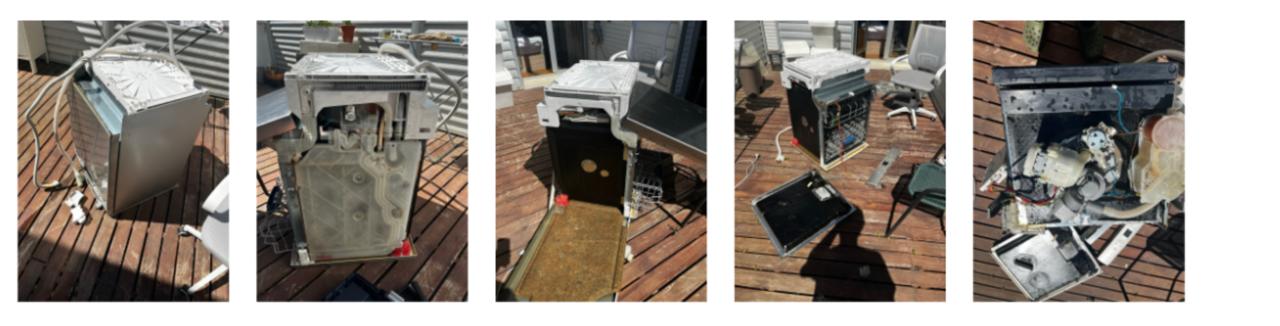
The teardown process was quite improvised — removing panels, disconnecting wiring, and progressively exposing internal systems.
Main observations:
- everything is tightly packed and optimized for space
- systems are highly integrated
- components are distributed physically but centrally controlled
The key aspect of this exercise is that I didn’t have to rebuild or fix the machine, so I could keep tearing it apart to its last component.
Main Control Board
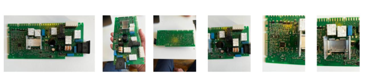
This is the core of the system.
Observations:
- dense PCB with mixed components
- connectors linking to all subsystems
- clear separation between power electronics and logic
Key elements identified:
- microcontroller (central control)
- relays / switching components
- power regulation
This is a centralized architecture where one board controls everything and there are no independent nodes.
Wiring Harness (System Backbone)
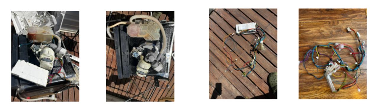
The wiring connects all subsystems.
Observations:
- color-coded cables
- multiple connectors
- point-to-point connections
- physical communication layer
Water Level Sensor
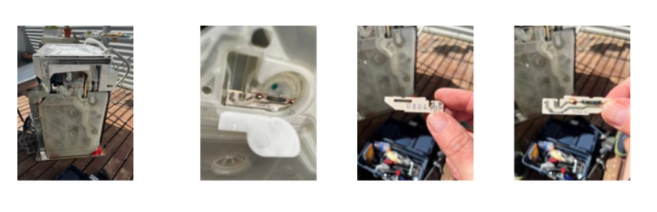
Located in a side chamber connected to water flow to detect water level via pressure or float mechanism
Observations:
- small sensing component inside plastic housing
- connected via simple wiring
- analog signal to main board
User Interface / Panel Board
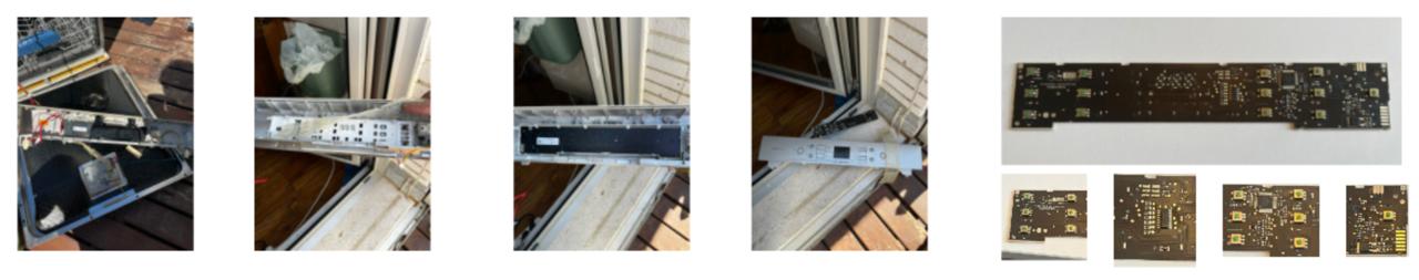
This is the interface between user and machine.
Observations:
- multiple buttons
- compact PCB
- separated from main board
- receives user input
- provides feedback (LEDs, indicators)
Pump + Motor System
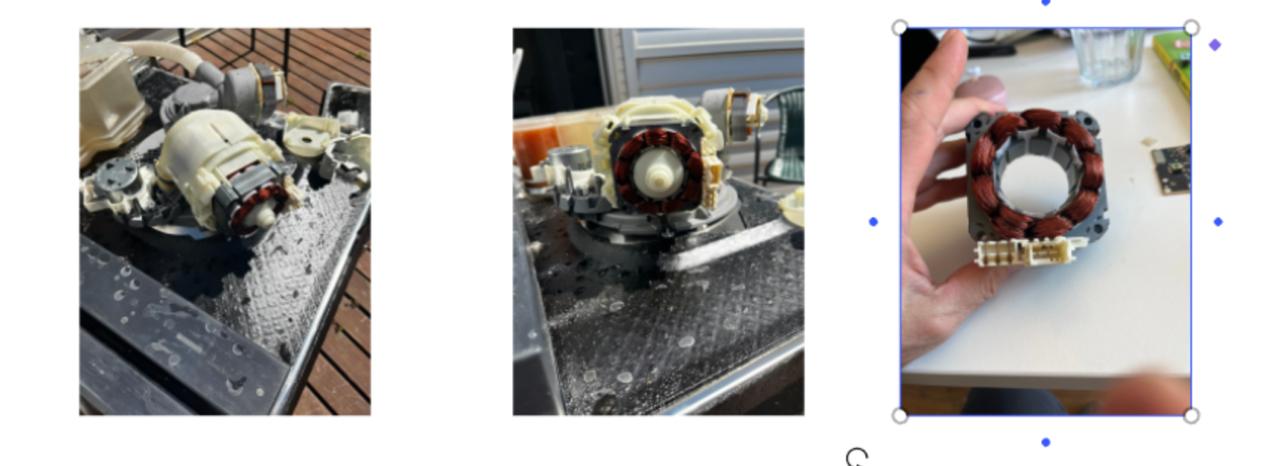
Main mechanical actuator of the system.
Observations:
- strong copper windings
- integrated pump and motor
- circulates water through the system
- contains heating element also
- controlled via power switching
Propeller / Internal Pump Components
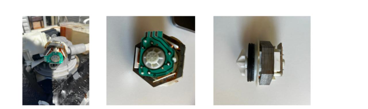
Internal parts connected to fluid movement.
Observations:
- compact assembly
- integrated with motor system
- convert rotational motion into water flow
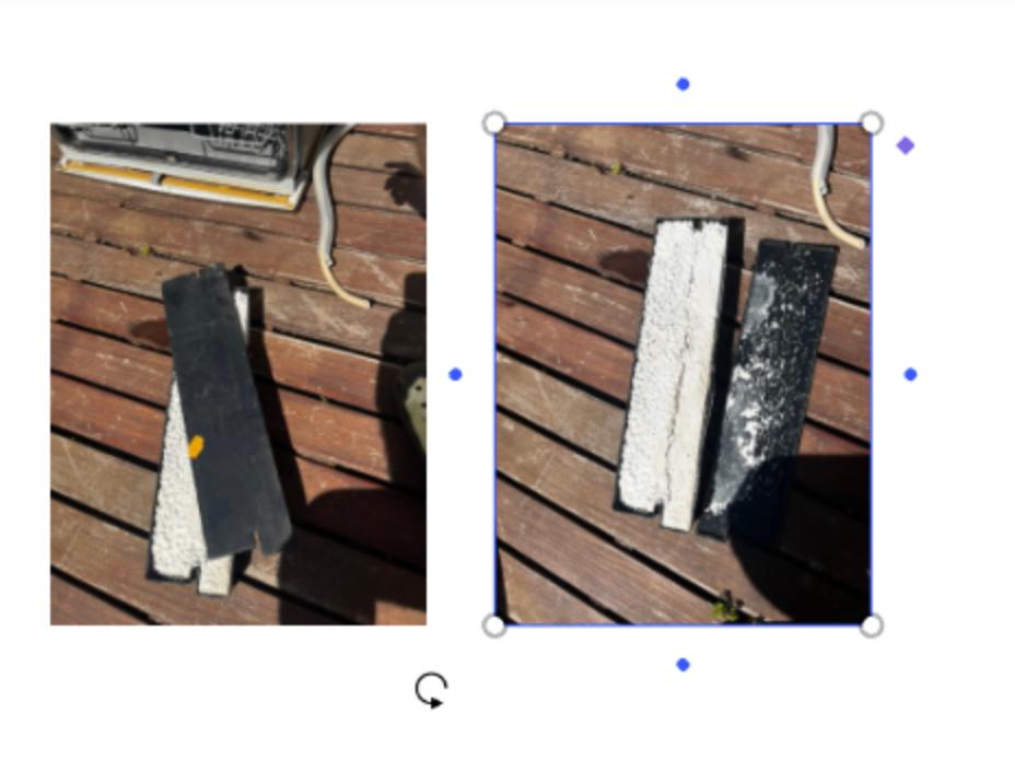
Heating Element
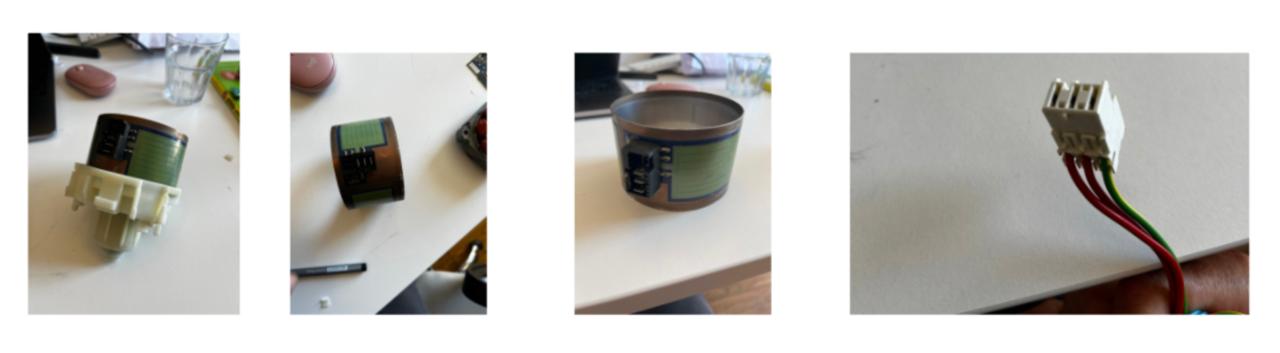
One of the most interesting discoveries.
Observations:
- cylindrical flexible element
- wrapped heater integrated inside pump housing
- heats water directly within the flow
- it is embedded into the hydraulic system
- integration between thermal and mechanical systems
Solenoid Valve
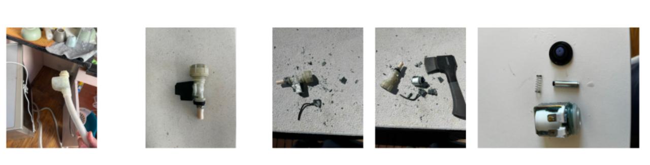
Controls water intake.
Observations:
- coil + spring + plunger mechanism
- opens/closes water flow
- simple ON/OFF control
Structural Elements
Additional mechanical components like weights and casing used for stability
Networking Perspective
Mapping to networking concepts:
| Dishwasher | Equivalent |
|---|---|
| Main MCU | Central server |
| Sensors | Input nodes |
| Actuators | Output nodes |
| Wiring | Physical layer |
| Signals | Simple protocol |
Learnings & Takeaways
The teardown exercise helped me debrief a lot of the concepts learned so far in the program, especially the electronic side and particularly this weeks focus on networks and communications.
Everything inside the dishwasher is:
- centralized
- tightly integrated
- voltage signals
- direct wiring
- simple ON/OFF control
No nodes talking to each other, no protocols — just one main controller and a bunch of passive components.
By breaking things open, following wires, identifying components and systems, I was able to figure out and understand the errors the machine was signaling that didn’t make it work properly beforehand.
Finding the heating system inside the pump was revealing as how deeply integrated mechanical, electrical, and thermal systems could potentially work for my final project.
Another important realization was how appliances often fail:
Even when most of the system is still working — structure, materials, molded parts, metal components — failure in electronics forces replacement of entire assemblies or even the full machine.
In this case, replacing a faulty electronic board ~€150 or heat pump ~€200 in a machine that costs ~€300 new does not make much sense.
Instead of discarding fully functional parts, A more modular design would allow:
- replacing only the faulty electronics
- or only the mechanical component that failed
This is directly relevant to ASFALT:
→ repurpose, upgrade equipment, don’t replace.
Finally, there’s something very satisfying and therapeutic about destroying a machine to understand how it works.
Week 11 — Networking and Communications
Assignment Goal
The goal of this week was to establish communication between multiple embedded devices and validate a distributed control architecture for the ASFALT project.
For ASFALT, this assignment was especially important because the final system is intended to operate as a modular network composed of:
- a user interface node
- a thermal control node
- sensing modules
- actuator control systems
- future telemetry and remote communication layers
The communication method explored during this week was UART serial communication between embedded boards.
Initial Development Phase — Waveshare ESP32-S3 SmartKnob Exploration
The first development phase focused on evaluating a compact rotary interface capable of:
- displaying a temperature setpoint
- detecting encoder rotation
- communicating with a secondary controller through UART
- acting as the operator interface for ASFALT
The first hardware candidate selected was the Waveshare ESP32-S3 SmartKnob.
Why the Waveshare SmartKnob
The Waveshare ESP32-S3 SmartKnob initially appeared to be a strong candidate because it integrated:
- ESP32-S3 microcontroller
- rotary encoder
- circular display
- compact enclosure
- USB-C communication
The idea was to use the SmartKnob as the front-end user interface while the ASFALT control PCB handled thermal control and outputs.
Initial Firmware Testing
Before attempting communication, I tested the board with a minimal firmware example to verify:
- USB communication
- board recognition
- firmware upload reliability
- serial monitor output
The first test simply printed an incrementing counter through Serial Monitor.
Firmware upload and serial verification
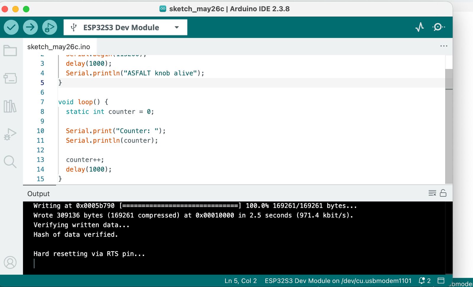
After several tries of connecting and disconnecting device and powering it on and off, the device was recognized by Arduino IDE. The firmware uploaded correctly, and apparently the serial monitor worked as expected.
UART Communication Investigation
The next objective was to establish UART communication between:
M5-style interface node
↓ UART
ASFALT controller PCB
To achieve this, I investigated the Waveshare pinout and internal connector mapping.
UART pinout investigation

I was having trouble identifying how to connect them, so I asked chatgpt to draw and image so I could visually makes sense of it and see if I could detect a problem.
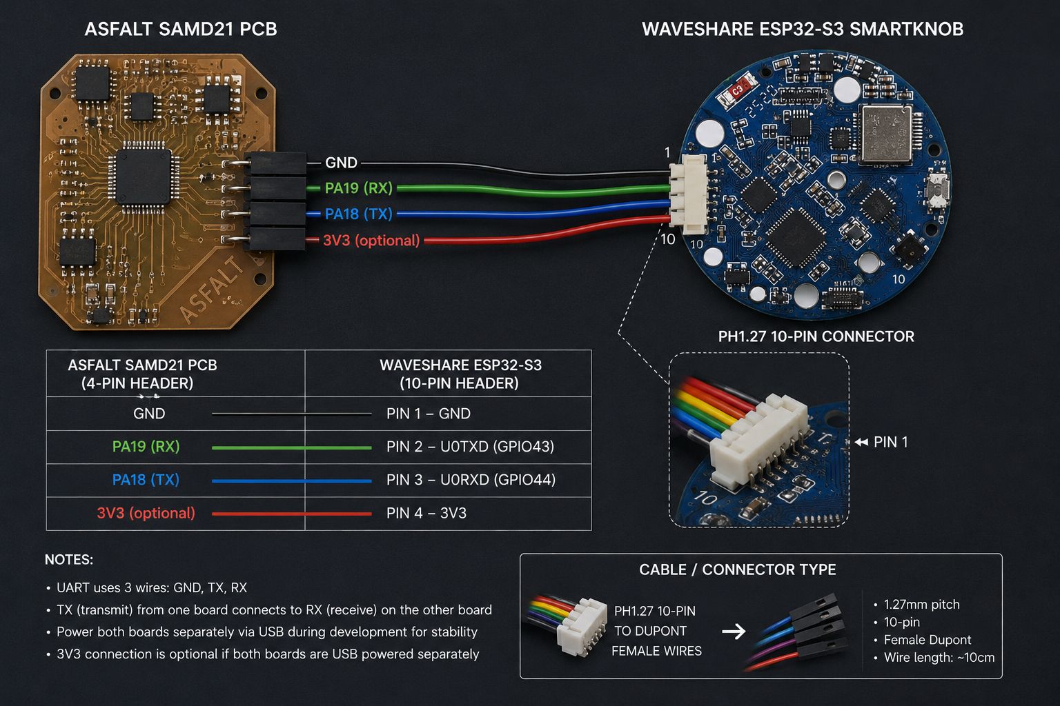
Intended UART Architecture
The planned wiring strategy was:
ASFALT PCB TX → SmartKnob RX
ASFALT PCB RX → SmartKnob TX
Shared GND
This became the first distributed communication architecture explored for ASFALT.
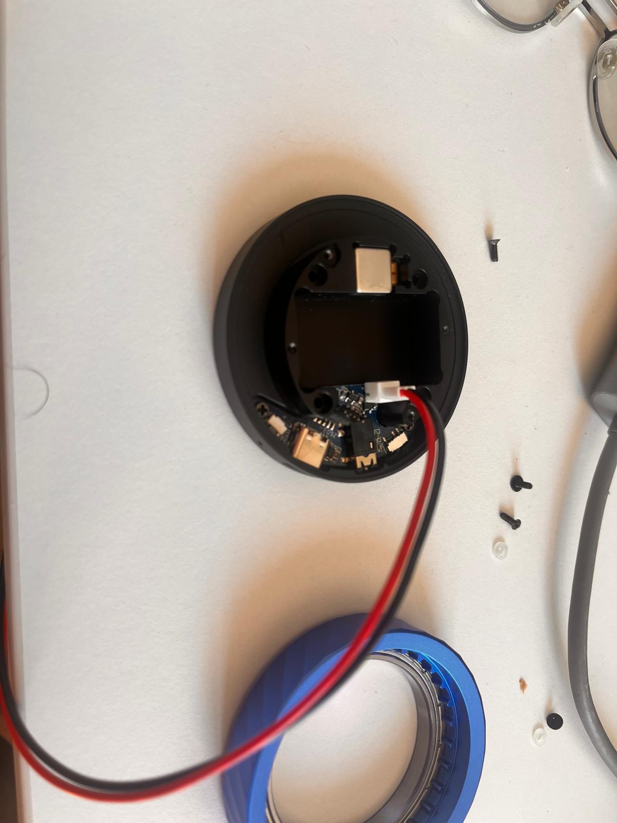
Hardware Inspection and Reverse Engineering
Because the available documentation for the board was limited, I first disassembled the device to understand:
- internal connector layout
- UART access possibilities
- mechanical assembly
- display and encoder integration
- expansion potential
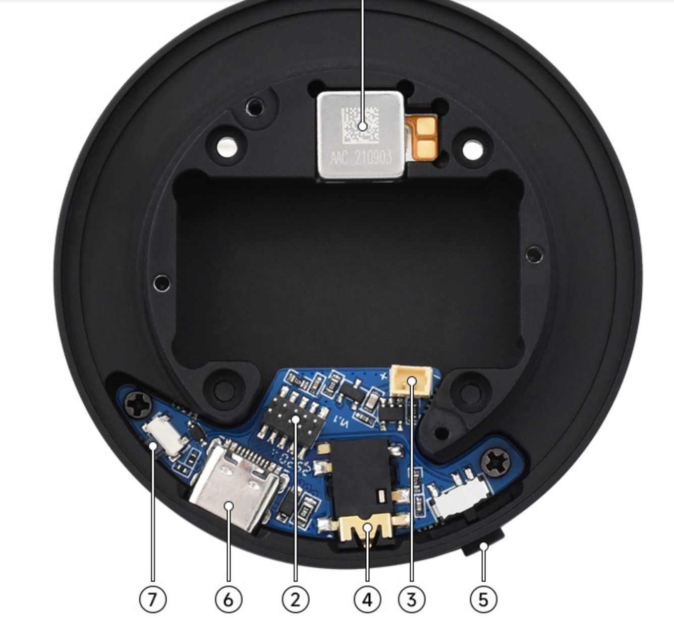
Internal SmartKnob inspection
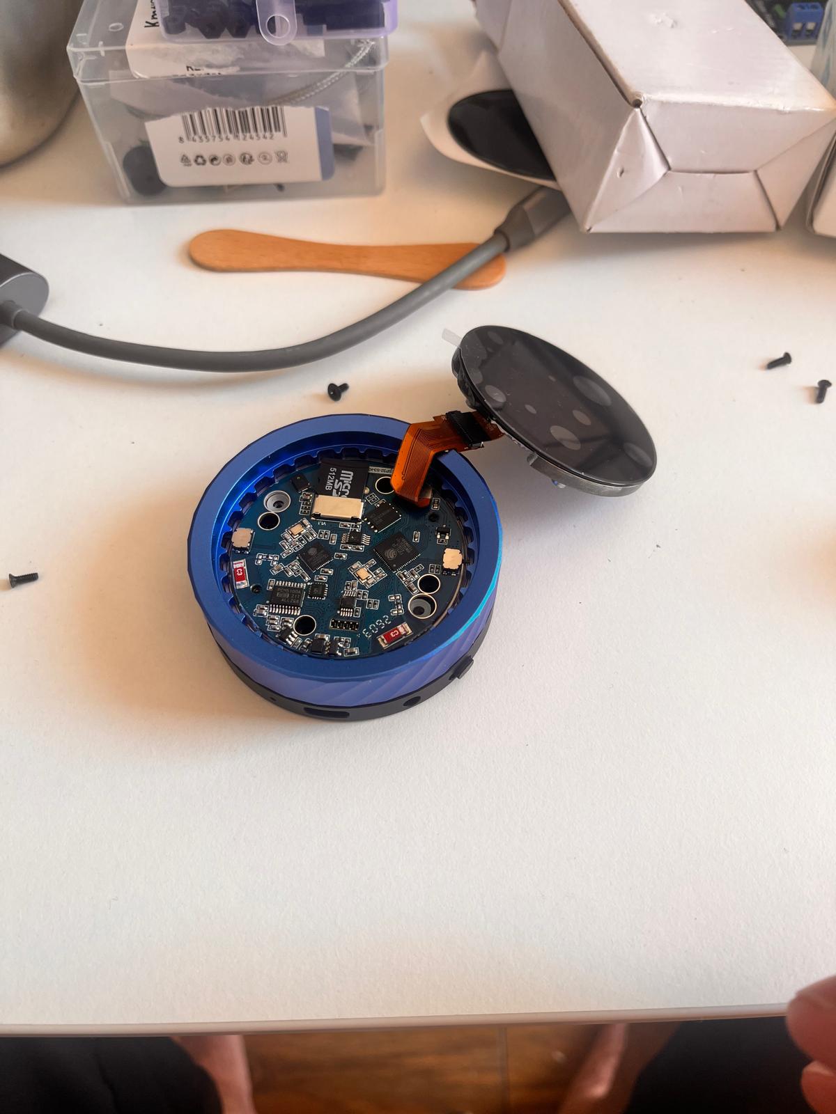
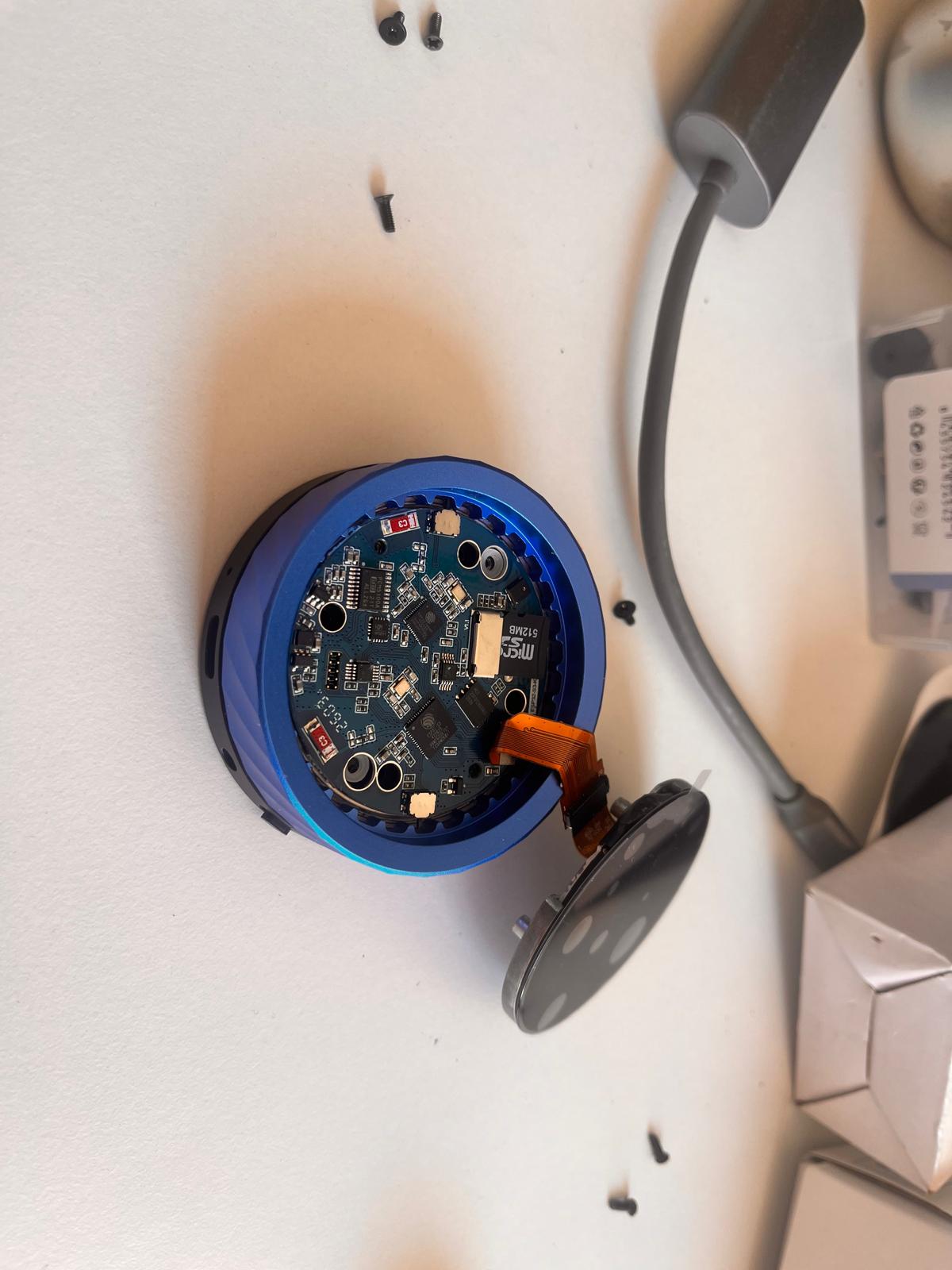
Observations During Inspection
Several important observations appeared during the teardown:
- the board used a compact stacked architecture
- UART pins were not directly accessible externally
- the encoder and display were tightly integrated
- the connector pitch was extremely small (PH1.27)
- development access required partial disassembly
This phase highlighted an important engineering lesson:
highly integrated consumer hardware can provide strong features while simultaneously reducing accessibility, repairability and debugging simplicity.
Problems Encountered with the Waveshare SmartKnob
As development continued, the SmartKnob introduced several integration problems.
- inconsistent encoder behavior
- unstable screen updates
- intermittent USB recognition
- very small connector pitch
- difficult probing and debugging
- limited documentation
- slower iteration during firmware testing
Although the board was technically powerful, it slowed development significantly during the communication testing phase.
Design Decision — Pivot to M5Dial
To continue progressing rapidly toward a working communication architecture, I temporarily abandoned the Waveshare SmartKnob and switched to the M5Dial.
The reasons for the pivot were:
- more stable USB communication
- easier UART access
- better Arduino ecosystem support
- faster debugging workflow
- reduced integration friction
This followed an important rapid prototyping principle used throughout ASFALT:
when one subsystem blocks progress, temporarily replace it with a more reliable platform so development of the overall system can continue.
The next architecture became:
M5Dial (UI node)
↓ UART
ASFALT PCB (controller node)
M5Dial + ASFALT PCB Communication Attempt
After replacing the Waveshare board, I began testing the M5Dial as the new interface node.
The goal of this phase was to transmit a temperature setpoint from the M5Dial to the ASFALT controller PCB through UART communication.
Why the M5Dial
The M5Dial became a much more suitable development platform because it provided:
- rotary encoder
- circular display
- ESP32-S3 microcontroller
- accessible Grove connector
- stable USB communication
- mature Arduino support
This made it ideal for quickly validating the communication architecture.
Initial Encoder and Display Testing
I first uploaded the standard encoder example to verify the hardware behavior.
Encoder test
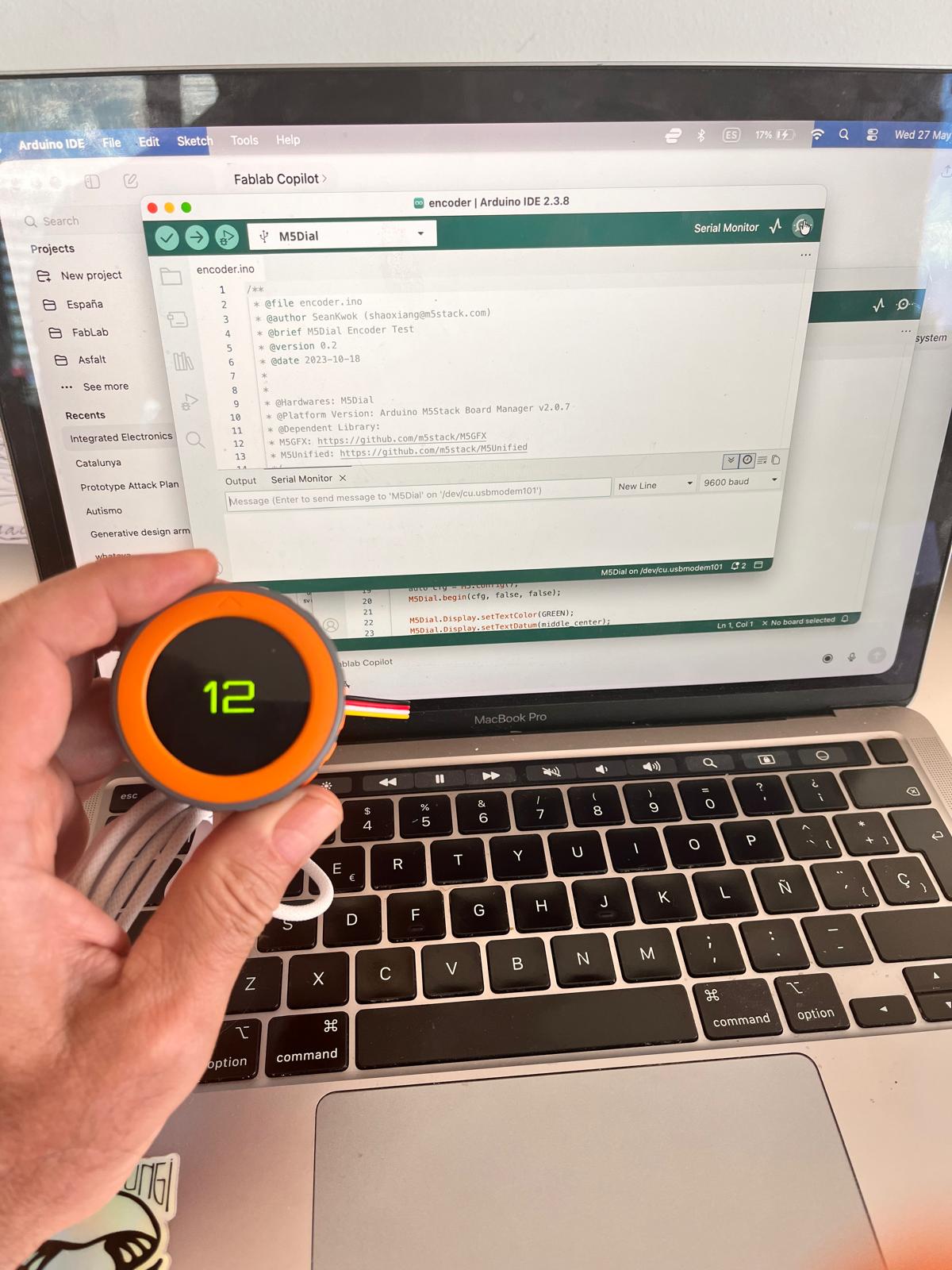
The test confirmed:
- successful firmware upload
- correct encoder operation
- live display updates
- proper library installation
Converting the Interface into an ASFALT Temperature Controller
I then modified the example so the encoder value represented a cooking temperature setpoint.
Temperature interface test
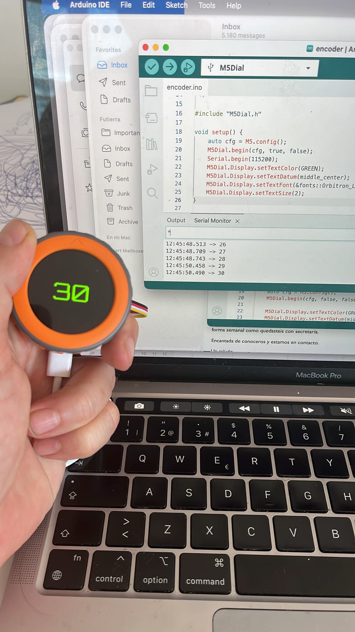
This transformed the M5Dial from a generic encoder demo into a dedicated ASFALT interface prototype.
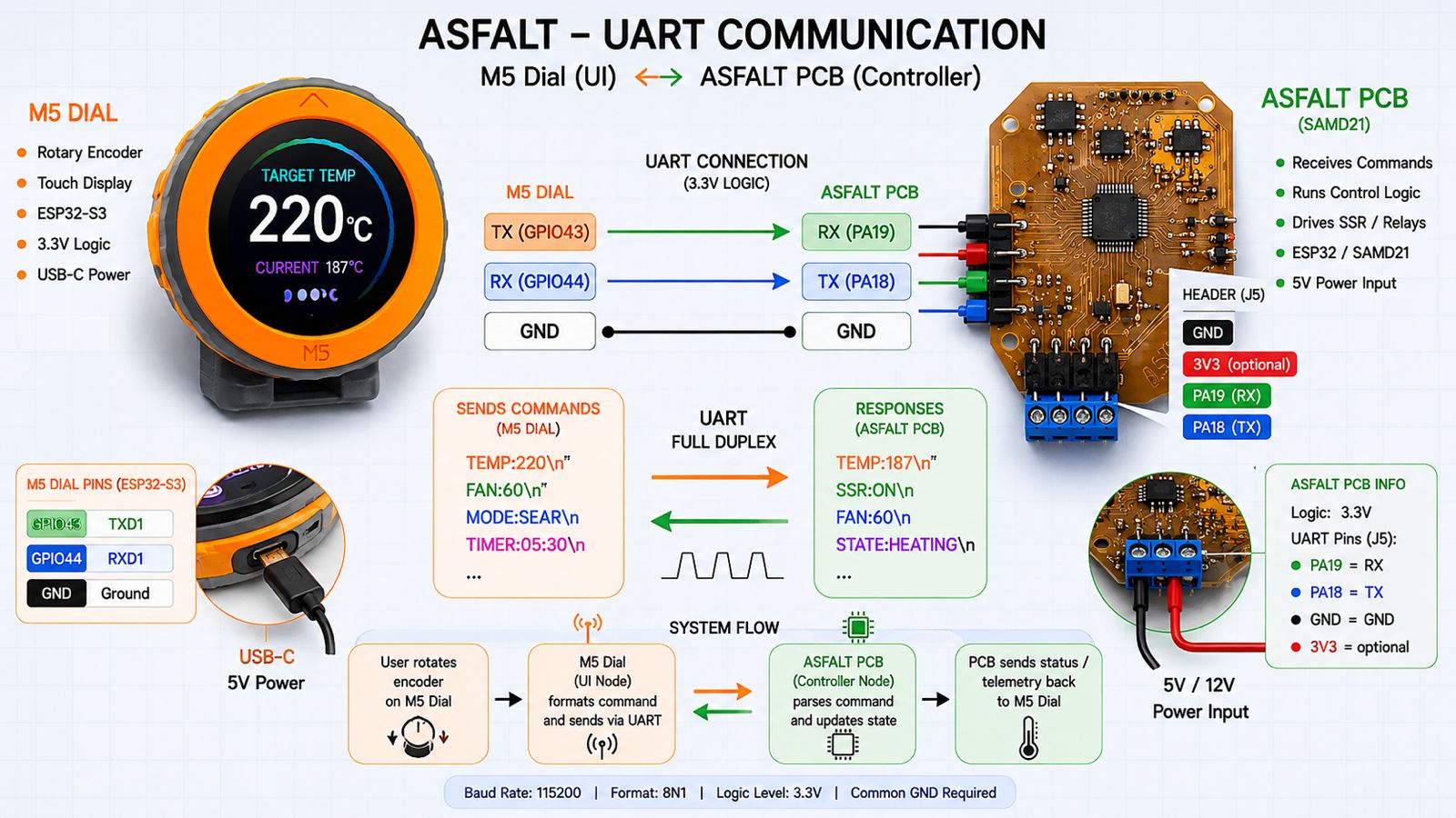
UART Communication Strategy
The next step was connecting the M5Dial to the ASFALT PCB through UART.
The communication parameters used were:
- TX from M5Dial → RX on ASFALT PCB
- RX from M5Dial → TX on ASFALT PCB
- shared GND
- 115200 baud
- 3.3V logic
The message structure was intentionally simple:
TEMP:220
This allowed the receiving controller to parse the selected temperature value easily.
UART communication architecture
Physical UART Wiring
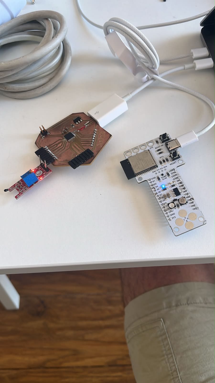
I connected the M5Dial to the ASFALT PCB using jumper wires.
Initial UART wiring
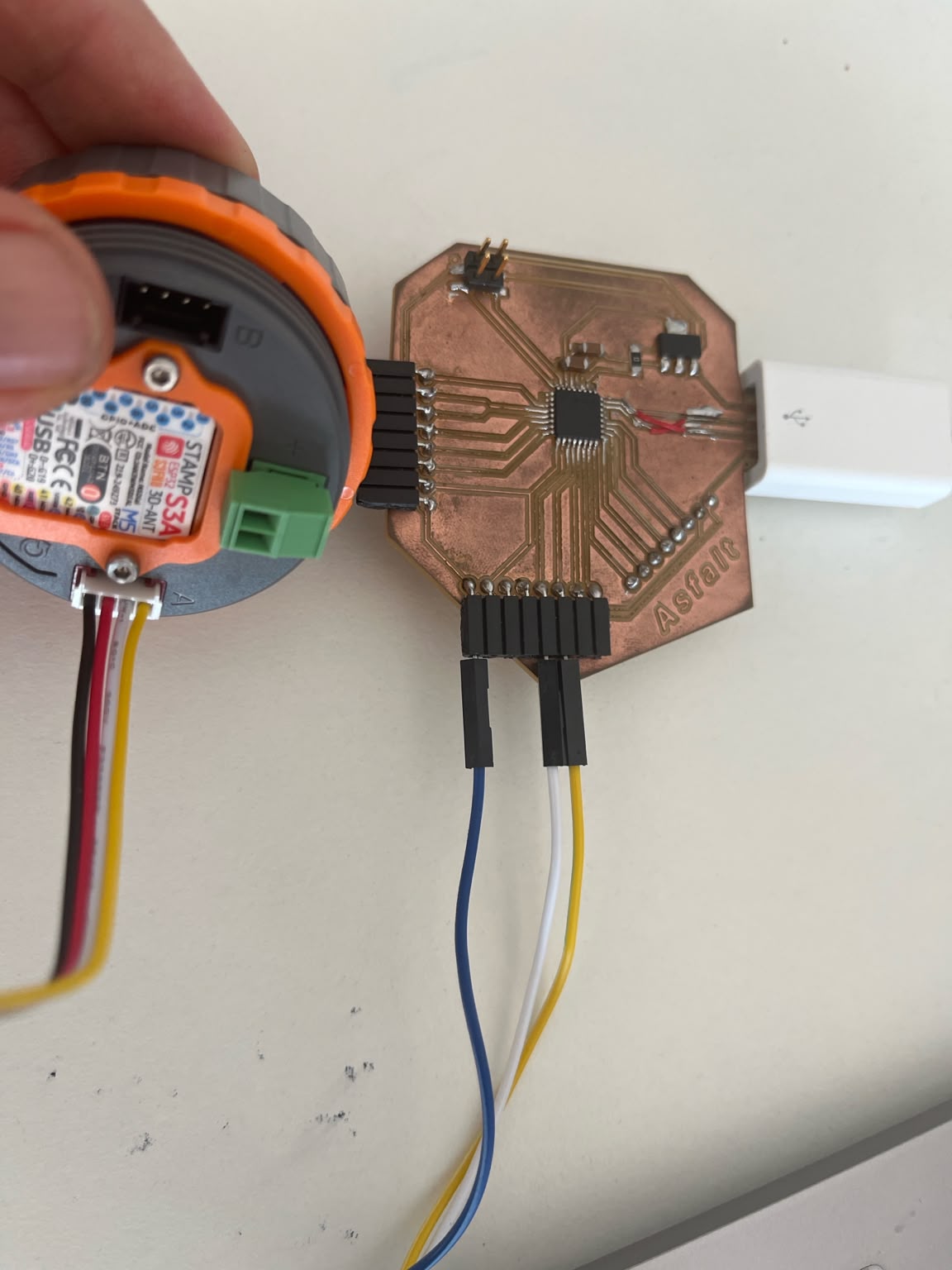
The intended connection was:
M5Dial TX → ASFALT PCB RX
M5Dial RX → ASFALT PCB TX
GND → GND
During early debugging I simplified the system to one-way communication:
M5Dial TX → ASFALT PCB RX
GND → GND
This reduced the number of unknown variables and simplified troubleshooting.
ASFALT PCB Communication Problems
The next major challenge appeared when attempting to use the custom ASFALT PCB as the controller node.
The board was based on the SAMD21 microcontroller and intended to become the central controller for:
- thermal logic
- relay / SSR control
- sensor acquisition
- UI communication
However, communication behavior became unstable.
USB Repair and Rework
The original USB traces on the hand-made PCB became damaged during soldering and handling, so I manually repaired the USB connection using bypass wires.
USB bypass repair
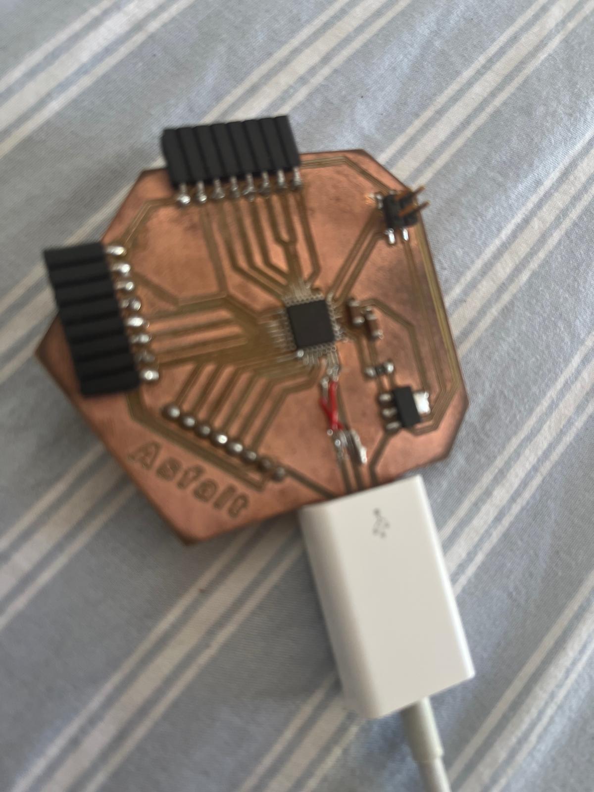
The repair restored power delivery through USB-C.
The board LED turned on consistently, confirming:
- 5V power was reaching the board
- the voltage regulator was functioning
- the SAMD21 was partially powered
However, USB communication itself remained unstable.
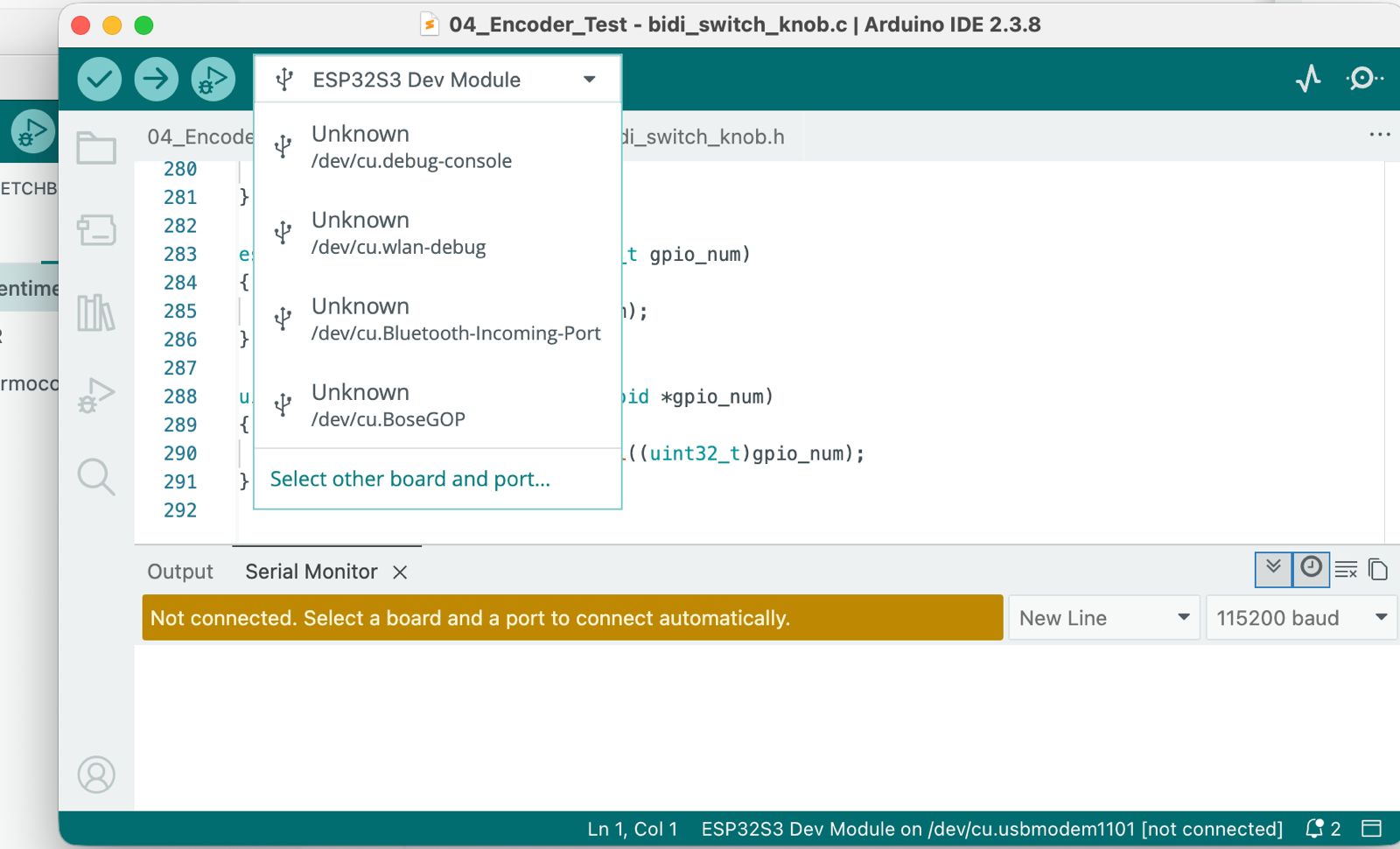
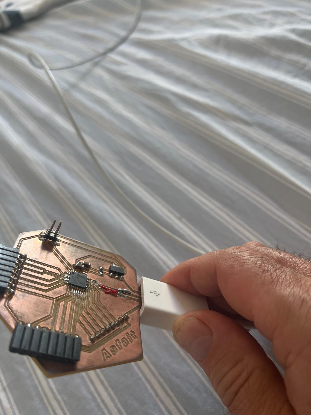
Intermittent USB Detection
One of the most frustrating aspects of debugging was that the board sometimes appeared functional.
Observed behavior included:
- Arduino IDE occasionally detecting the board
- the USB port appearing and disappearing
- uploads failing randomly
- serial monitor disconnecting
- unstable bootloader communication
At times the IDE recognized the board correctly:
/dev/cu.usbmodem…
But communication could not be maintained consistently.
Unstable USB communication behavior
This created a difficult debugging situation because:
- the board had power
- the USB port occasionally appeared
- uploads sometimes began successfully
- communication failed unpredictably
UART Communication Attempts
I attempted several UART communication tests between the M5Dial and the ASFALT PCB.
Communication testing setup
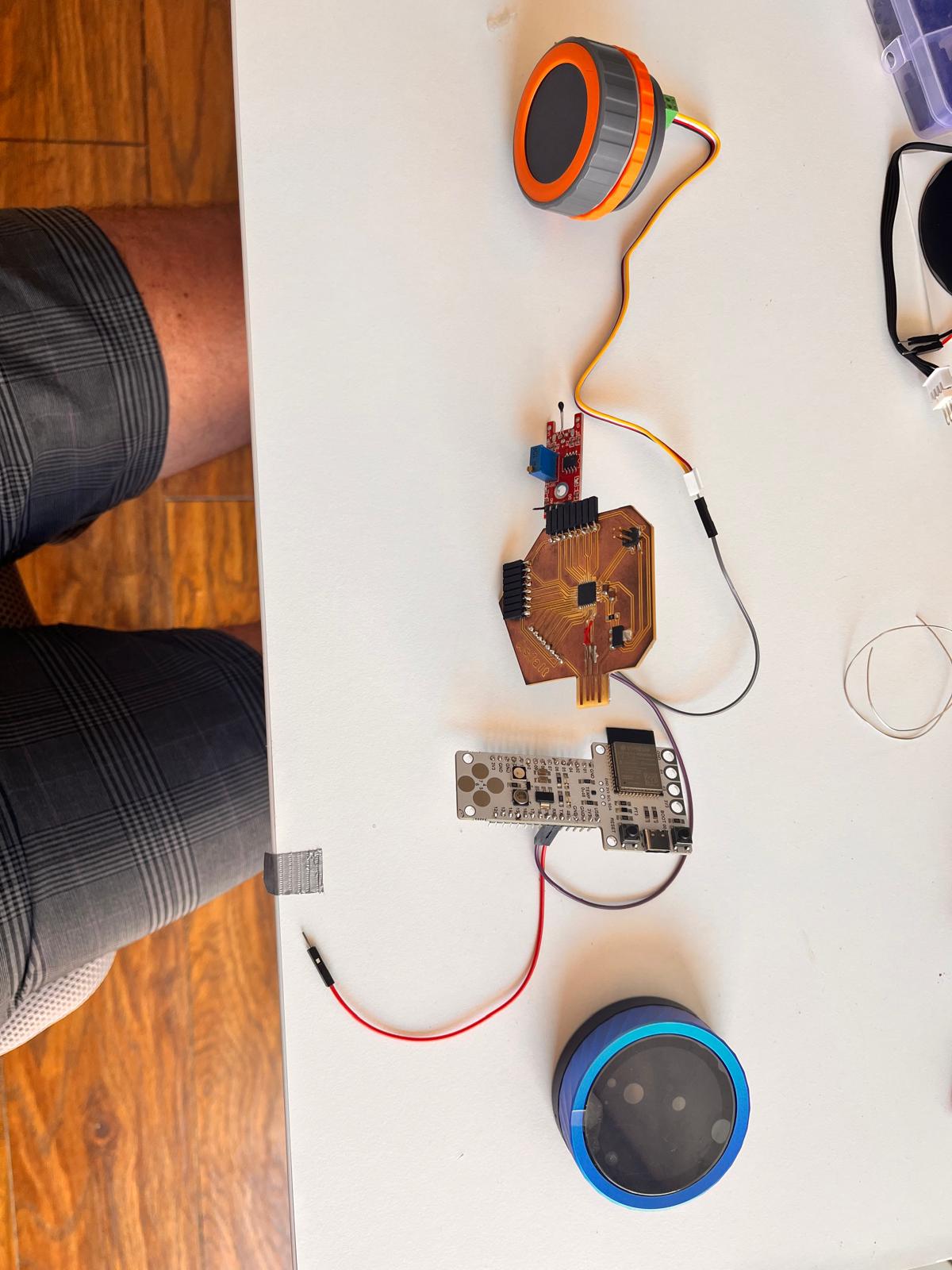
During these experiments:
- the M5Dial transmitted correctly
- the encoder and display worked reliably
- UART messages appeared valid
- the ASFALT PCB failed to respond consistently
The serial monitor occasionally produced corrupted characters instead of readable messages.
This suggested unstable UART communication or unreliable USB serial behavior on the repaired PCB.
Multimeter Continuity Testing
To isolate possible hardware failures, I performed continuity tests with a multimeter.
Continuity and debugging tests
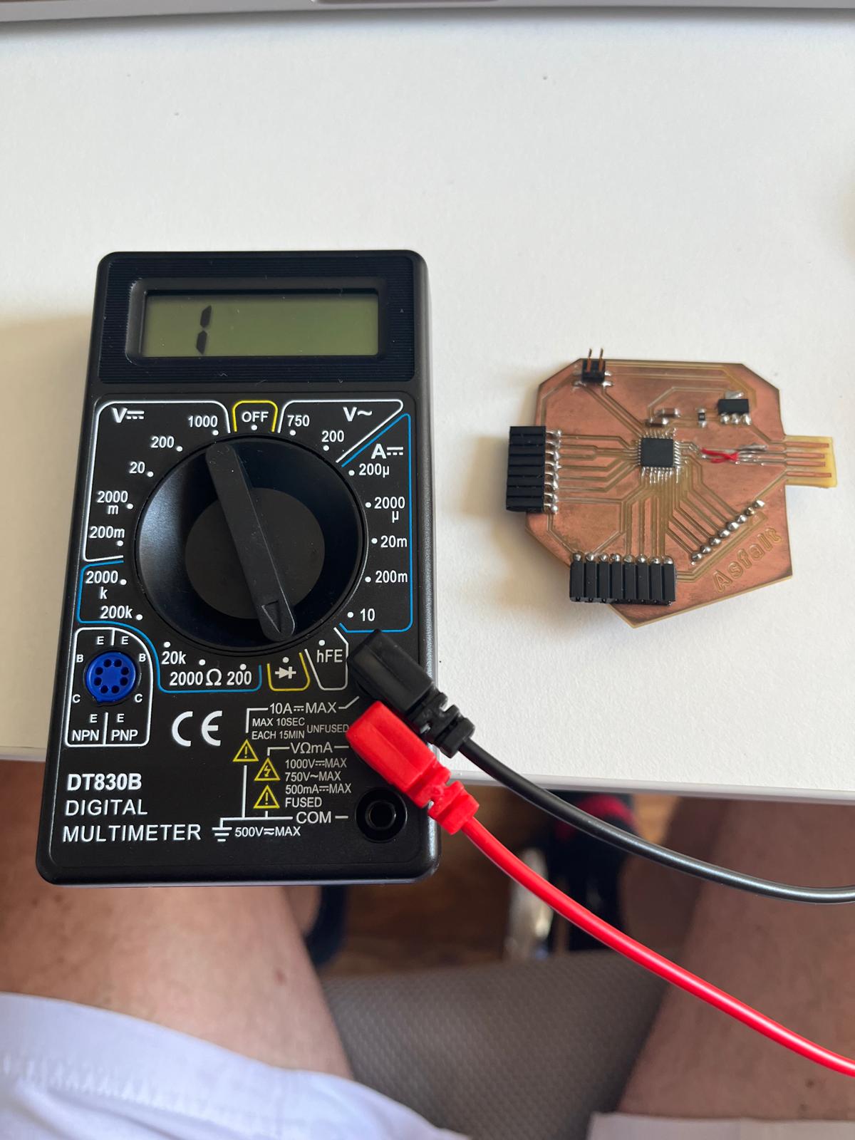
The tests suggested:
- USB data lines were not shorted together
- power and ground were not directly shorted
- repaired traces still had continuity
- the problem was likely intermittent or mechanical
The issue was therefore probably related to:
- fragile solder joints
- damaged USB traces
- unstable repaired connections
- unreliable physical contact
rather than a complete electrical short circuit.
Decision to Pause the ASFALT PCB
At this stage, continuing to debug the repaired PCB was consuming too much time for the assignment timeline.
Since professionally manufactured PCBWay versions of the ASFALT PCB were already in production, I decided to temporarily stop using the hand-reworked board.
Instead of blocking progress, I replaced the unstable controller node with a Barduino ESP32-S3 development board.
This allowed development of the networking architecture to continue while preserving the same communication strategy.
The updated architecture became:
M5Dial (UI node)
↓ UART
Barduino ESP32-S3 (controller node)
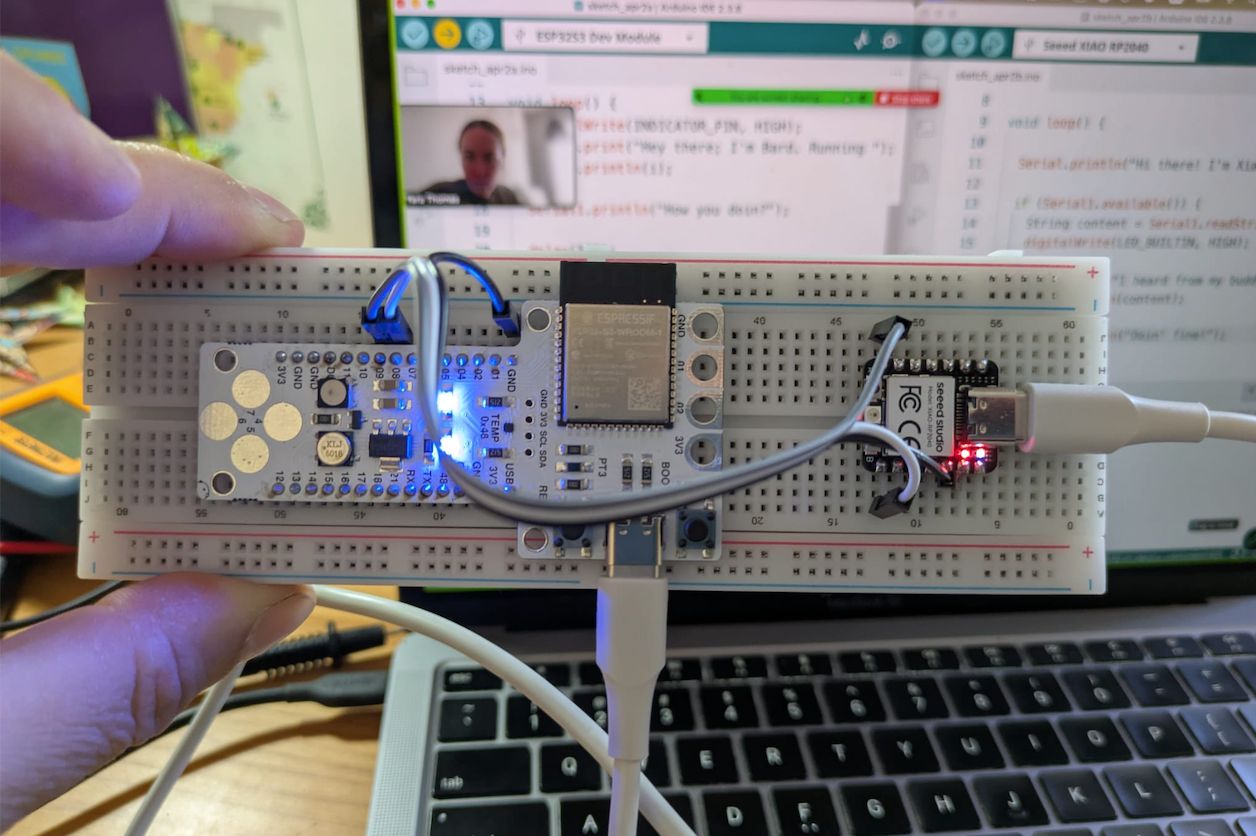
Switching to Barduino and Achieving Stable UART Communication
The Barduino board was used as a stable replacement controller node for the networking experiments.
The objective was to validate:
- UART communication
- real-time parameter transmission
- distributed controller logic
- modular UI/control separation
without being blocked by hardware instability on the custom PCB.
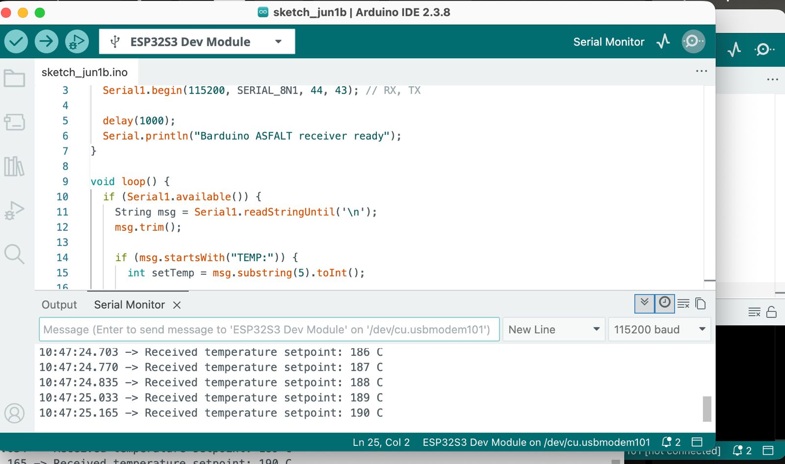
Barduino UART Receiver Setup
The Barduino board was configured as the UART receiver.
The UART configuration used:
- RX = GPIO44
- TX = GPIO43
- shared GND
- 115200 baud
The receiver parsed messages in the format:
TEMP:190
and extracted the temperature value as an integer.
UART receiver implementation
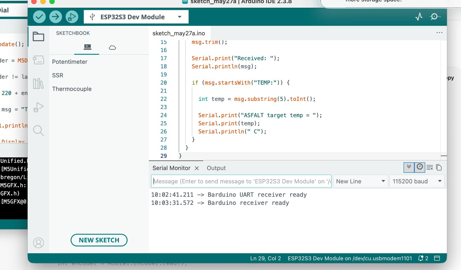
The serial monitor successfully displayed:
Received temperature setpoint: 186 C
Received temperature setpoint: 187 C
Received temperature setpoint: 188 C
This confirmed stable UART communication.
Physical UART Wiring
The M5Dial and Barduino boards were connected directly through jumper wires.
UART wiring between M5Dial and Barduino
The wiring used:
M5Dial TX → Barduino RX
M5Dial RX → Barduino TX
GND → GND
The labeled development board significantly reduced debugging uncertainty compared to the custom PCB.
Pin Verification
Before testing communication, I verified the Barduino UART pin locations directly on the board.
Barduino UART pin verification
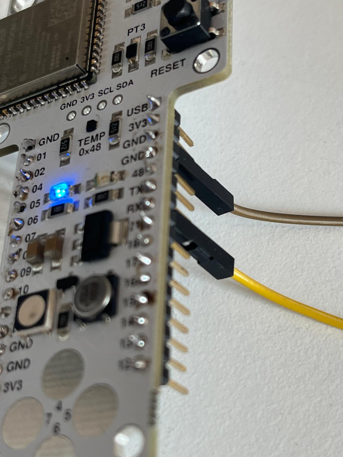
This helped avoid common UART issues such as:
- TX/RX inversion
- missing common ground
- incorrect GPIO assignments
- use of reserved pins
Successful Distributed Communication
Once the connection stabilized, the M5Dial successfully transmitted changing temperature setpoints to the Barduino controller.
The communication workflow became:
User rotates encoder
↓
M5Dial updates temperature
↓
UART message transmitted
↓
Barduino receives command
↓
Temperature setpoint parsed
The communication was continuous and stable.
ESP-NOW Wireless Communication Test
After validating stable UART communication between the M5Dial and Barduino boards, I wanted to evaluate whether the same distributed architecture could work wirelessly using ESP-NOW. Since I had already abandoned the SAMD21 Asfalt board without wireless connection, I decided to try communicating between 2 ESP that I had at hand.
I looked at different options, and ESP-NOW was selected because it is:
- lightweight
- peer-to-peer
- low latency
- supported directly by ESP32 devices
- simpler than WiFi networking for embedded communication
AI-Assisted Development
For this experiment, I used ChatGPT extensively to:
- generate the ESP-NOW communication code
- configure sender and receiver logic
- structure packet transmission
- debug wireless communication setup
- understand ESP32 peer-to-peer networking
The complete ESP-NOW implementation was produced collaboratively through iterative prompting and testing with ChatGPT.
This significantly accelerated development because I wanted to quickly test if wireless comms was and option and I don’t have the coding abilities to write it myself.
ESP-NOW Architecture
The wireless architecture became:
M5Dial (UI Node)
↓ ESP-NOW wireless communication ↓
Barduino ESP32-S3 (Controller Node)
The M5Dial transmitted the selected temperature setpoint wirelessly while the Barduino received and parsed the incoming values.
M5Dial Wireless Sender
The M5Dial continued functioning as the operator interface.
The encoder controlled the temperature setpoint while the display updated in real time.
Each encoder movement transmitted a wireless ESP-NOW packet containing the selected temperature.
The transmitted message structure was intentionally simple:
TEMP = 233 °C
This maintained the same communication logic previously used during UART testing.
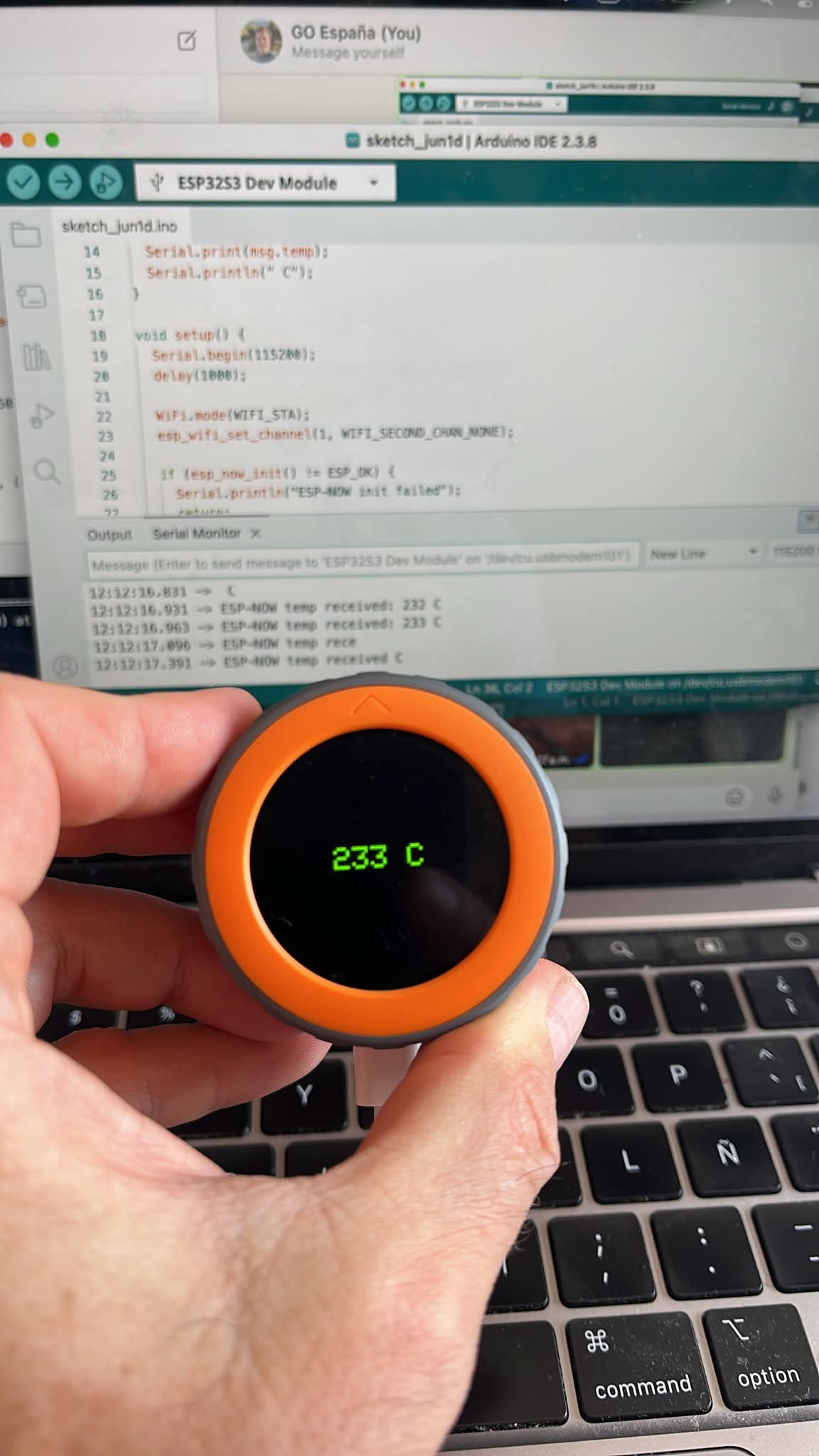
Barduino Wireless Receiver
The Barduino board was configured as the ESP-NOW receiver node.
Incoming packets were received and printed through the Serial Monitor.
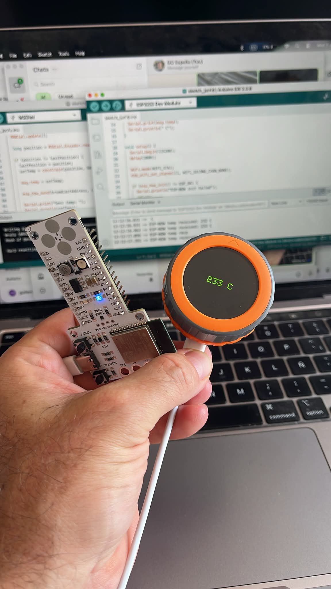
The Serial Monitor successfully displayed incoming wireless temperature updates such as:
- ESP-NOW temp received: 232 C
- ESP-NOW temp received: 233 C
This confirmed that:
- wireless communication was functioning correctly
- the M5Dial was transmitting reliably
- Barduino successfully parsed the incoming data
- the architecture worked without physical TX/RX wiring
Here are both codes that Chatgpt created and I literally copy pasted into Arduino IDE.
M5Dial ESP-NOW Sender Code
#include <M5Dial.h>
#include <WiFi.h>
#include <esp_now.h>

typedef struct struct_message {
  int temp;
} struct_message;

struct_message msg;

uint8_t receiverAddress[] = {0x24, 0x6F, 0x28, 0xAA, 0xBB, 0xCC};

esp_now_peer_info_t peerInfo;

int tempValue = 220;

void setup() {
  auto cfg = M5.config();
  M5Dial.begin(cfg, true, false);

  Serial.begin(115200);

  M5Dial.Display.setTextColor(GREEN);
  M5Dial.Display.setTextDatum(middle_center);
  M5Dial.Display.setTextSize(2);

  WiFi.mode(WIFI_STA);

  if (esp_now_init() != ESP_OK) {
    Serial.println("ESP-NOW init failed");
    return;
  }

  memcpy(peerInfo.peer_addr, receiverAddress, 6);
  peerInfo.channel = 1;
  peerInfo.encrypt = false;

  esp_now_add_peer(&peerInfo);
}

void loop() {

  M5Dial.update();

  int encoder = M5Dial.Encoder.read();

  tempValue = 220 + encoder;

  M5Dial.Display.clear();
  M5Dial.Display.drawString(String(tempValue) + " C", 120, 120);

  msg.temp = tempValue;

  esp_now_send(receiverAddress, (uint8_t *) &msg, sizeof(msg));

  delay(100);
}
Barduino ESP-NOW Receiver Code
#include <WiFi.h>
#include <esp_now.h>

typedef struct struct_message {
  int temp;
} struct_message;

struct_message incomingMsg;

void OnDataRecv(const esp_now_recv_info *info, const uint8_t *incomingData, int len) {

  memcpy(&incomingMsg, incomingData, sizeof(incomingMsg));

  Serial.print("ESP-NOW temp received: ");
  Serial.print(incomingMsg.temp);
  Serial.println(" C");
}

void setup() {

  Serial.begin(115200);

  WiFi.mode(WIFI_STA);

  esp_wifi_set_channel(1, WIFI_SECOND_CHAN_NONE);

  if (esp_now_init() != ESP_OK) {
    Serial.println("ESP-NOW init failed");
    return;
  }

  esp_now_register_recv_cb(OnDataRecv);

  Serial.println("ESP-NOW receiver ready");
}

void loop() {

}
Results
This became the first fully working wireless network architecture for ASFALT.
The system now supported both wired UART communication and wireless ESP-NOW communication using nearly the same controller logic.
Reflection
This weeks assigemnt significantly changed the perceived feasibility of the ASFALT electronics architecture.
Initially, I expected wired UART communication to remain the primary networking solution because it is simple, deterministic, and easy to debug.
However, after the ESP-NOW experiment, wireless communication appeared surprisingly practical for ASFALT.
The main advantages observed were:
- elimination of TX/RX wiring
- cleaner physical integration
- easier modular separation
- simpler enclosure routing
- improved flexibility for future nodes
- reduced connector complexity
For a foodservice equipment environment, reducing visible cables near the operator area could become a major advantage.
The controller box could remain positioned in the rear structure near the moving arm and power electronics, while only the rotary interface would remain close to the operator.
This would create:
- cleaner countertop space
- better operator ergonomics
- improved separation between electronics and heat
- reduced cable management
- easier maintenance and modular replacement
One thing that confirmed and was validated is that the interface node and the control node should remain physically independent.
This creates several long-term advantages:
- modular electronics
- easier maintenance
- safer thermal isolation
- scalable communication systems
- simpler firmware development
- future wireless expansion possibilities
Even though the original ASFALT PCB was temporarily replaced during debugging, the overall distributed system logic remained fully aligned with the final project goals. I will have to reasess convenience of changing to a native wireless chip (not SAMD21) for future development…
Use of AI
Artificial intelligence tools were used extensively throughout this assignment as part of the development, debugging, and documentation workflow. As with previous weeks, I leaned towards useing the Fablab Co-pilot I created to support with:
- generating ESP32 UART communication code
- developing ESP-NOW wireless communication logic
- debugging serial communication issues
- sender/receiver communication
- accelerating rapid prototyping iterations
- organizing documentation structure
The workflow was highly iterative.Instead of copying complete solutions directly, I used conversational prompting to:
- test multiple architectures
- simplify debugging paths
- isolate communication problems
- understand why failures occurred
- compare wired vs wireless networking approaches
- refine system-level design decisions
Examples of prompts used during development included:
- “How can I establish UART communication between two ESP32 boards?”
- “How should I structure a distributed controller architecture?”
- “How can I debug unstable UART communication?”
- “What is the best option to communicate wirelessly between M5 and Barduino boards?”
- “What are the advantages of ESP-NOW over UART for embedded systems?”
- “Write code to establish wireless comms via esp-now between them”
AI assistance became especially valuable during ESP-NOW implementation for speed and a final reflection is that I wouldn’t have been able to acheive it otherwise.