Week 16 — System Integration
Global Class
This week focused on one of the most critical aspects of digital fabrication projects: system integration. The lecture emphasized that successful projects are not only about creating individual parts, but about designing how all components function together as a coherent and reliable system.
A strong focus was placed on failure modes and how projects often fail due to poor integration, weak packaging, unreliable wiring or lack of testing. The importance of designing assemblies, cable routing, PCB mounting and structural tolerances from the beginning of the design process was repeatedly highlighted.
The lecture also introduced important design principles such as minimizing complexity, reducing unnecessary parts, designing for manufacturing (DFM), and incorporating flexibility into assemblies to compensate for fabrication inaccuracies.
Another key topic was packaging and presentation quality. Attention was given not only to functionality, but also to surface finish, accessibility, maintainability and the physical organization of electronics and wiring.
Testing and quality assurance were presented as fundamental parts of development. Rather than avoiding failure, the goal is to anticipate problems early and design systems that are easier to debug, assemble and maintain.
This lecture reinforced the importance of thinking about projects as complete systems instead of isolated technical exercises.
Weekly assignment
Structural Arm Prototype
One of the main goals during System Integration week was to move beyond isolated parts and begin assembling a coherent physical subsystem for ASFALT.
The focus was the articulated support arm intended to hold and position the upper heating module above the cooking surface. This prototype became an important exercise in understanding how structure, mounting, tolerances and assembly interact in a real physical system.
Initial Assembly and Structural Testing
The process started by unpacking and evaluating the monitor-arm-inspired structural components that would later become part of the adjustable support mechanism.
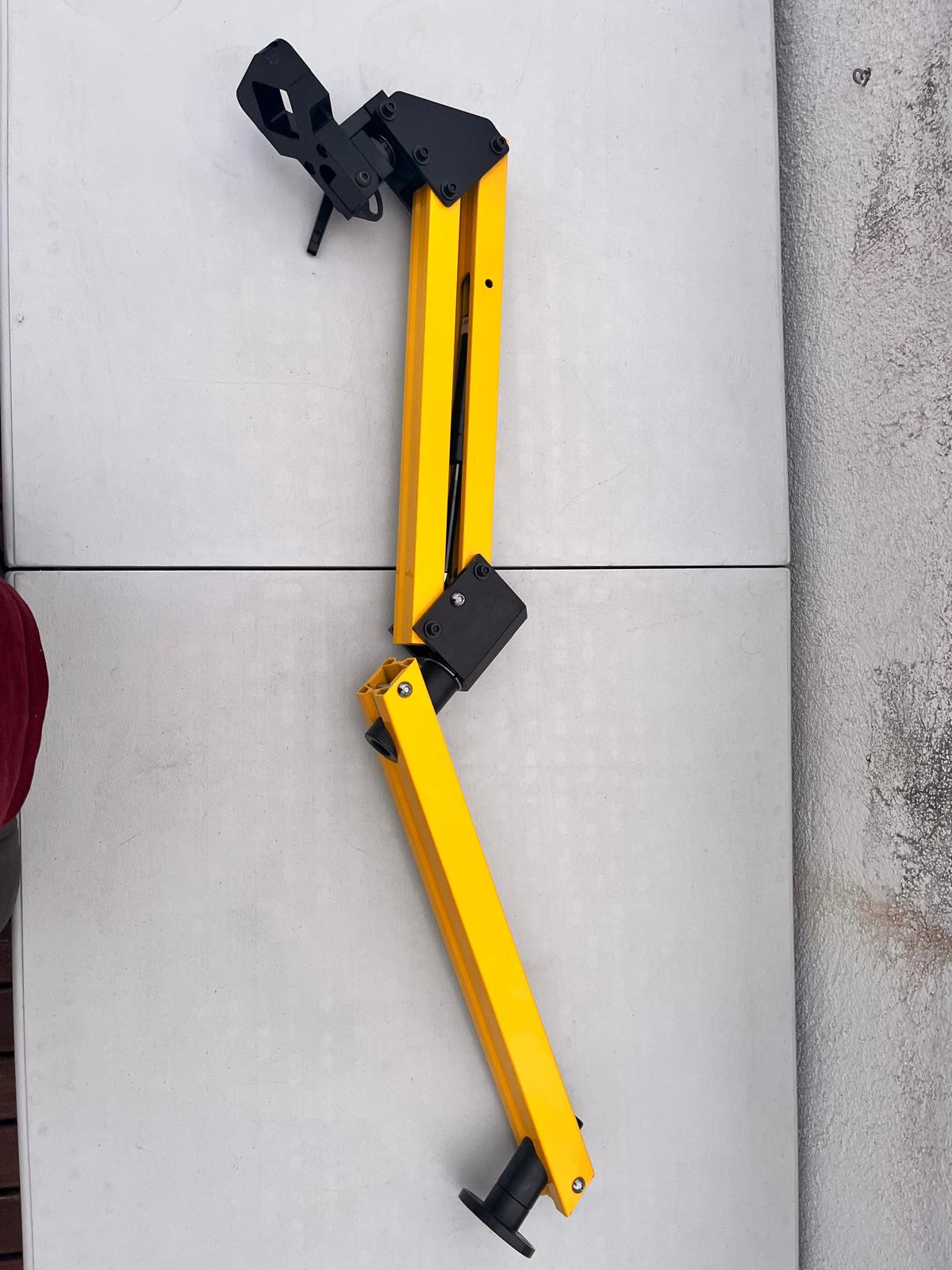
At this stage, the priority was not aesthetics but understanding:
- joint behavior
- rigidity
- mounting geometry
- possible ranges of motion
- integration constraints with the cooking structure
Fabricating the Base
To integrate the arm into the larger prototype, I needed a rigid mounting interface between the structural arm and the supporting base.
Using a steel plate as an intermediate bracket, I manually marked and drilled the required mounting holes to match the arm geometry.
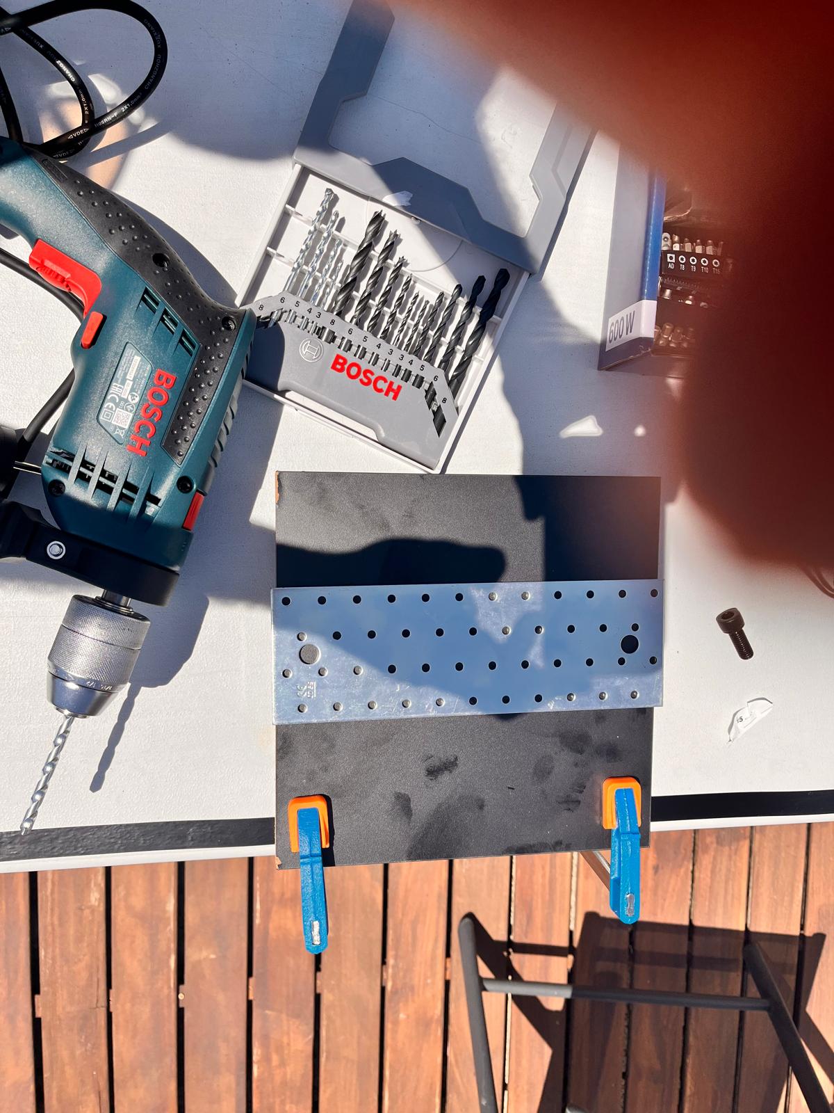
The process involved:
- measuring hole spacing manually
- clamping the workpiece to reduce vibration
- drilling progressively larger diameters
- verifying alignment against the arm base
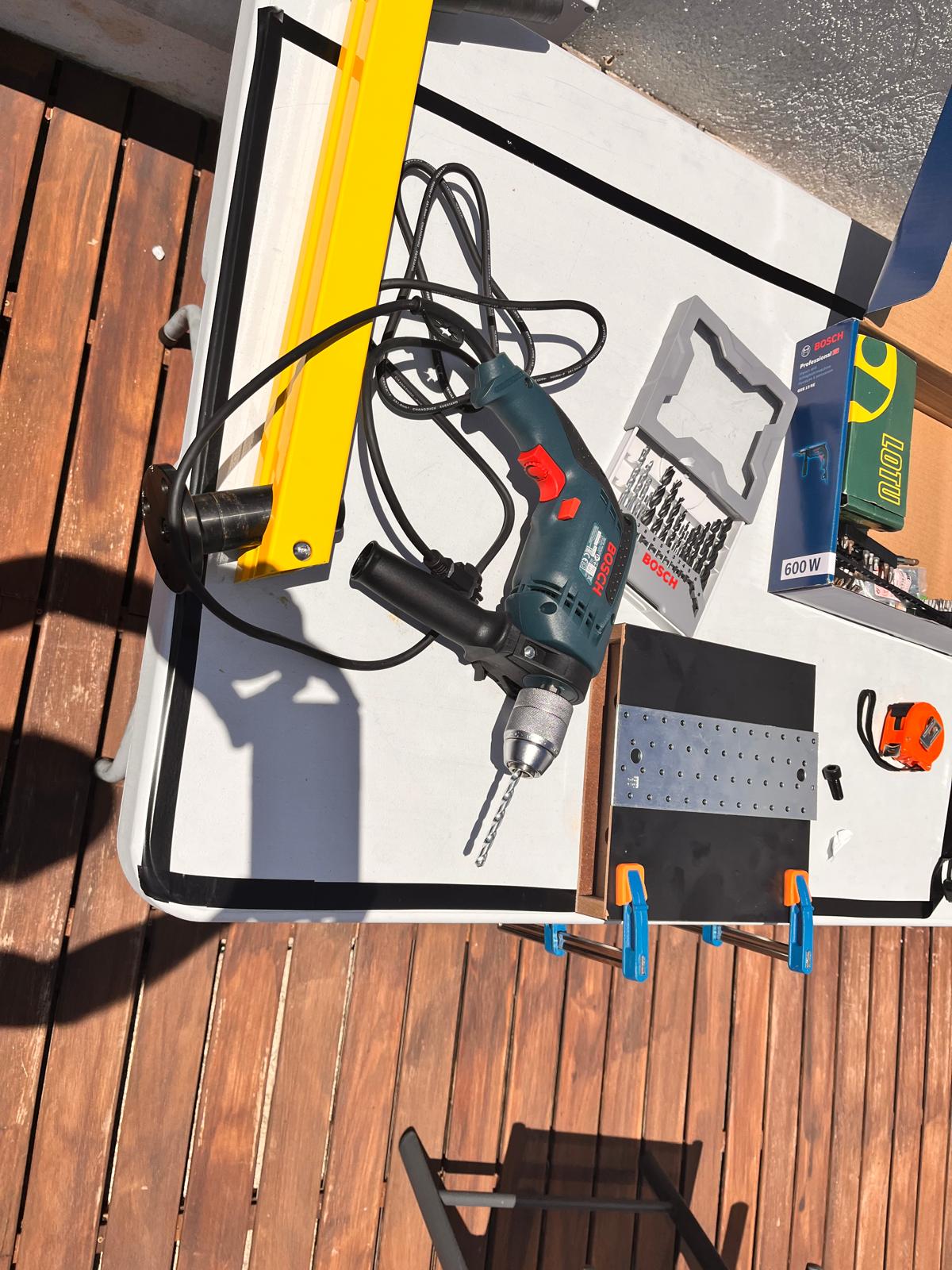
This step highlighted how quickly small dimensional inaccuracies accumulate during integration work. Even slight deviations in drilling alignment affected assembly precision and required iterative adjustment.
Early System Integration Experiments
I started experimenting with how the heating assembly could physically connect to the structure.
This stage was very hands-on and exploratory. The goal was not to build a final solution yet, but to quickly test relationships between:
- heater position
- reflector geometry
- mounting angles
- structural support
- adjustability
- assembly feasibility
A large part of this process involved improvising with available materials, adapting existing parts and observing what physically made sense once components were combined together.
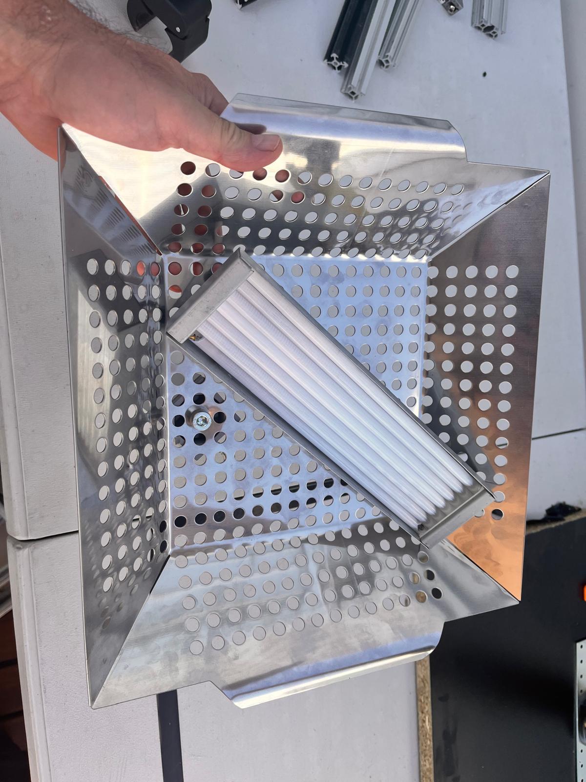
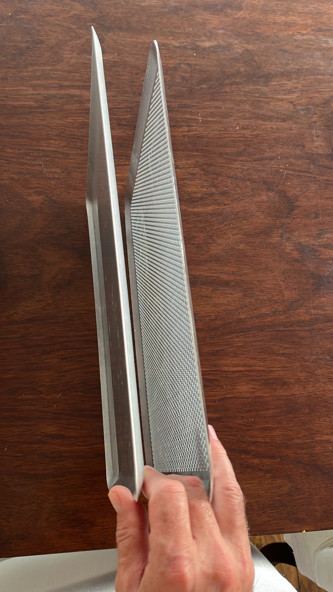
Testing Reflector Geometry
I started experimenting with stainless steel perforated trays as potential reflective surfaces for the upper heating module.
The perforated geometry was interesting because it combined:
- lightweight construction
- rigidity after folding
- reflective properties
- airflow openings
- easy mounting possibilities through existing holes
At this point I was mainly trying to understand whether a folded reflective geometry could help direct heat downward while remaining mechanically simple.
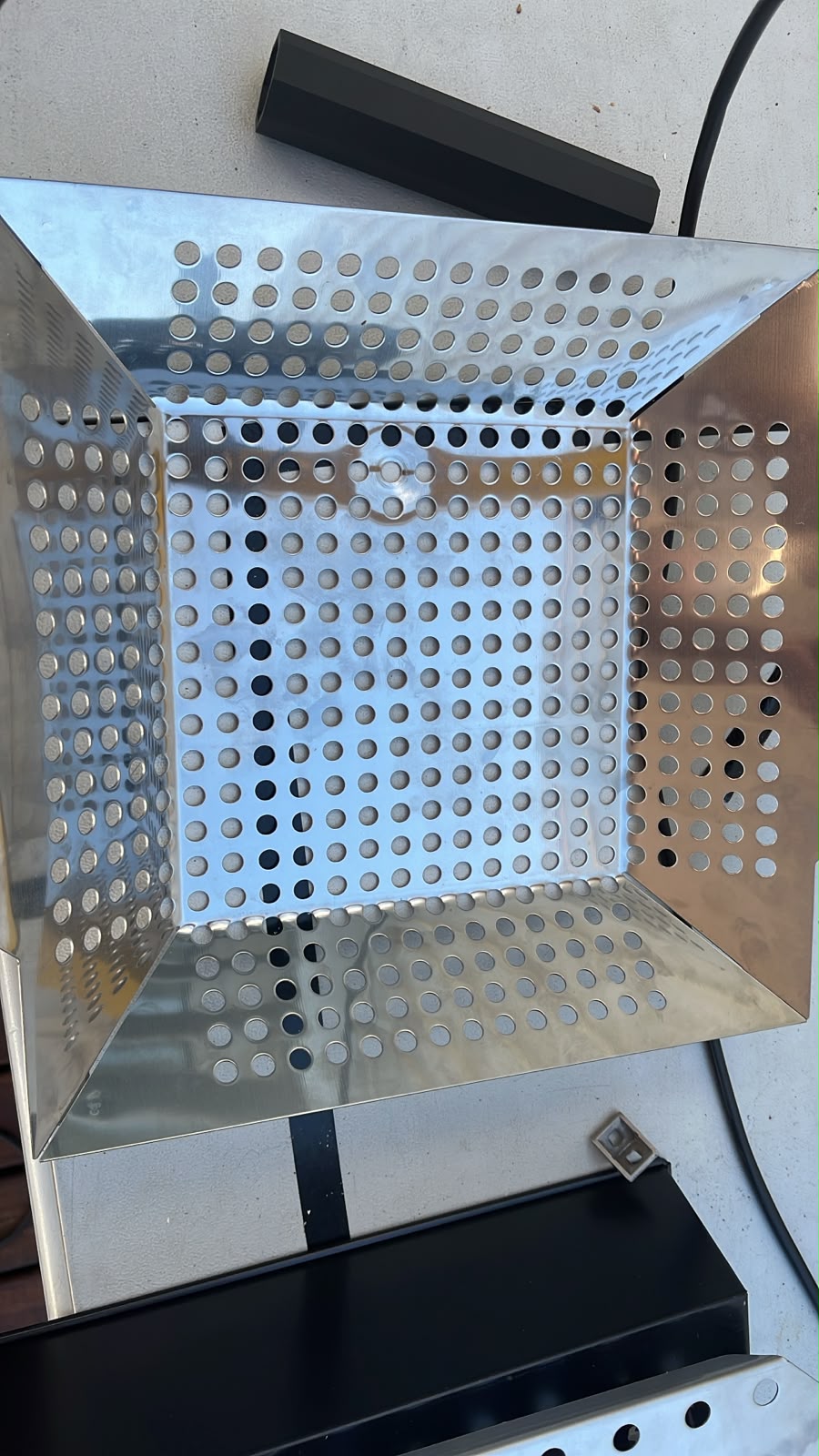
The angled surfaces immediately created a more directional geometry than the earlier flat concepts. Even without active heating tests yet, this already felt closer to the spatial behavior I imagined for ASFALT.
Exploring Heater Positioning
Once the reflector shape felt promising, I began experimenting with how the ceramic infrared heater could sit inside the structure.
Rather than centering the heater immediately, I intentionally tested diagonal placement to better understand:
- mounting constraints
- cable routing
- reflected heat direction
- available internal space
- interaction with the arm movement
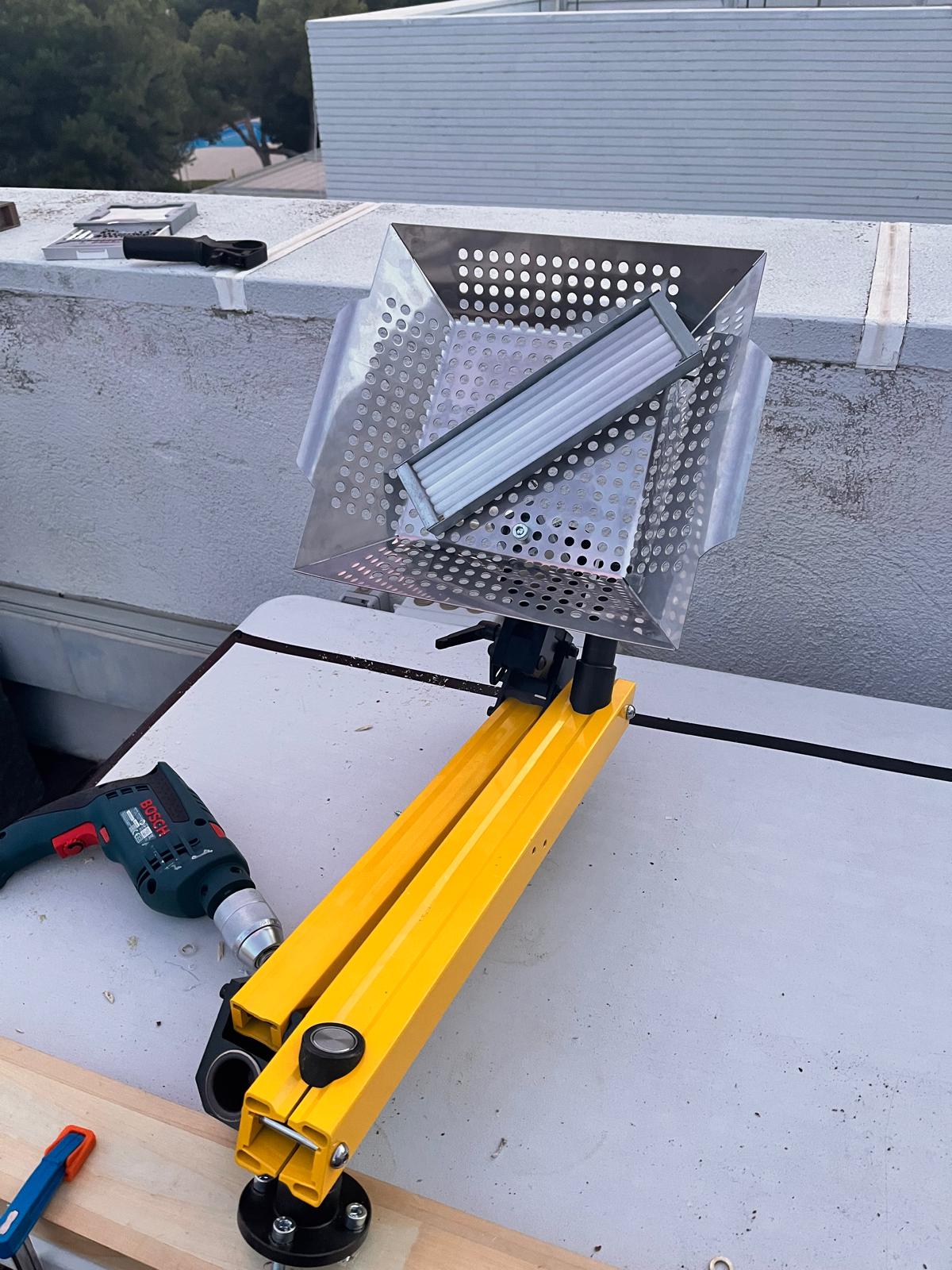
This phase involved a lot of repositioning, temporary fasteners and visual testing. I was trying to learn what configurations felt mechanically believable before committing to more permanent fabrication decisions.
Building a Structural Connection
The next challenge was attaching the reflector assembly to the articulated arm.
To do this, I experimented with a square aluminum profile mounted underneath the reflector tray. This became a quick structural adapter between the reflector assembly and the arm mechanism.
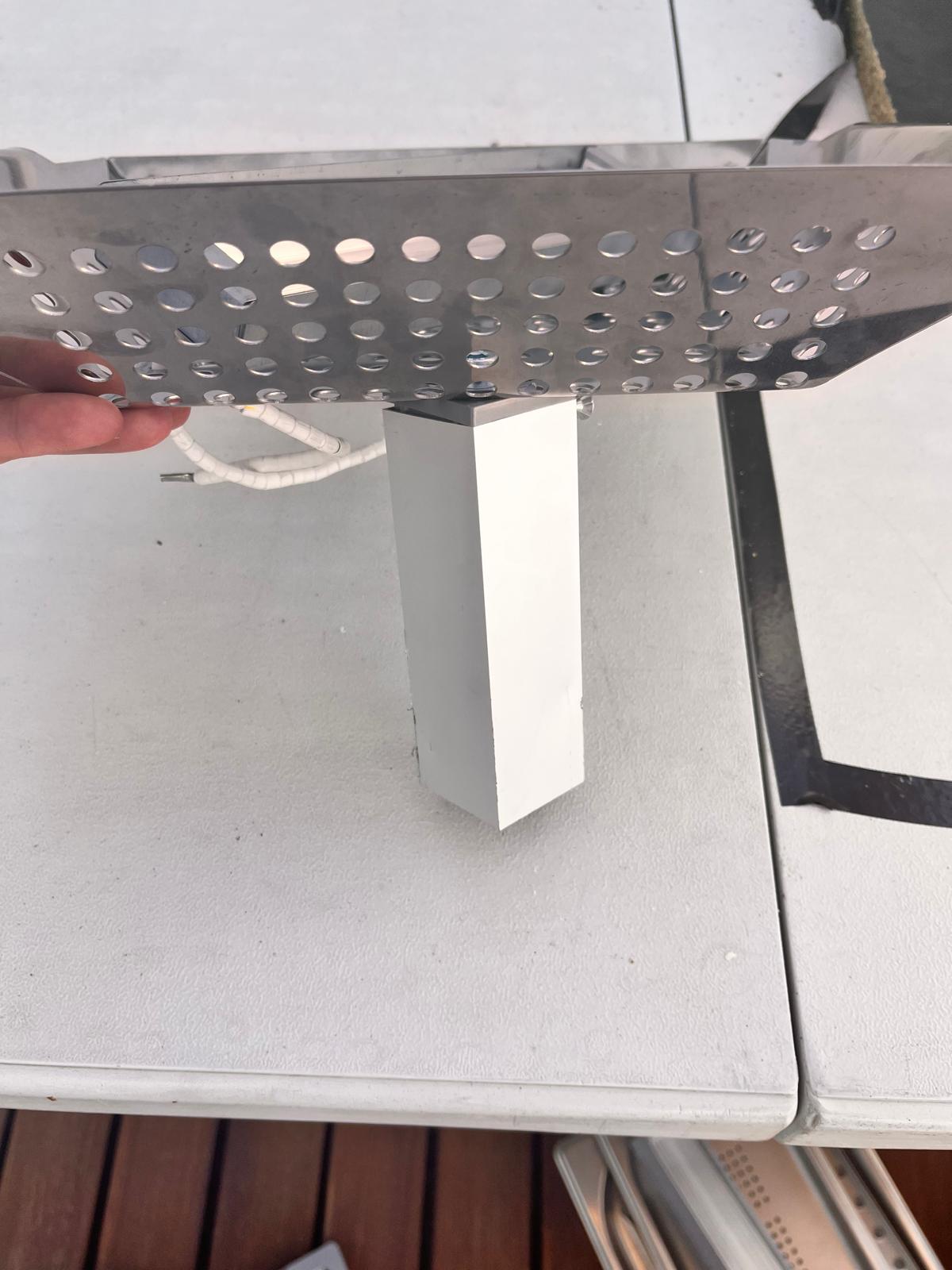
This solution was improvised but useful because it allowed fast testing of:
- weight distribution
- center of gravity
- rotational behavior
- structural stiffness
- mounting accessibility
At this stage, speed of experimentation mattered more than elegance.
Integrating Reflector and Arm
Once the aluminum support profile was attached, I could finally connect the reflector assembly to the yellow articulated arm and begin testing the entire upper structure as one integrated object.
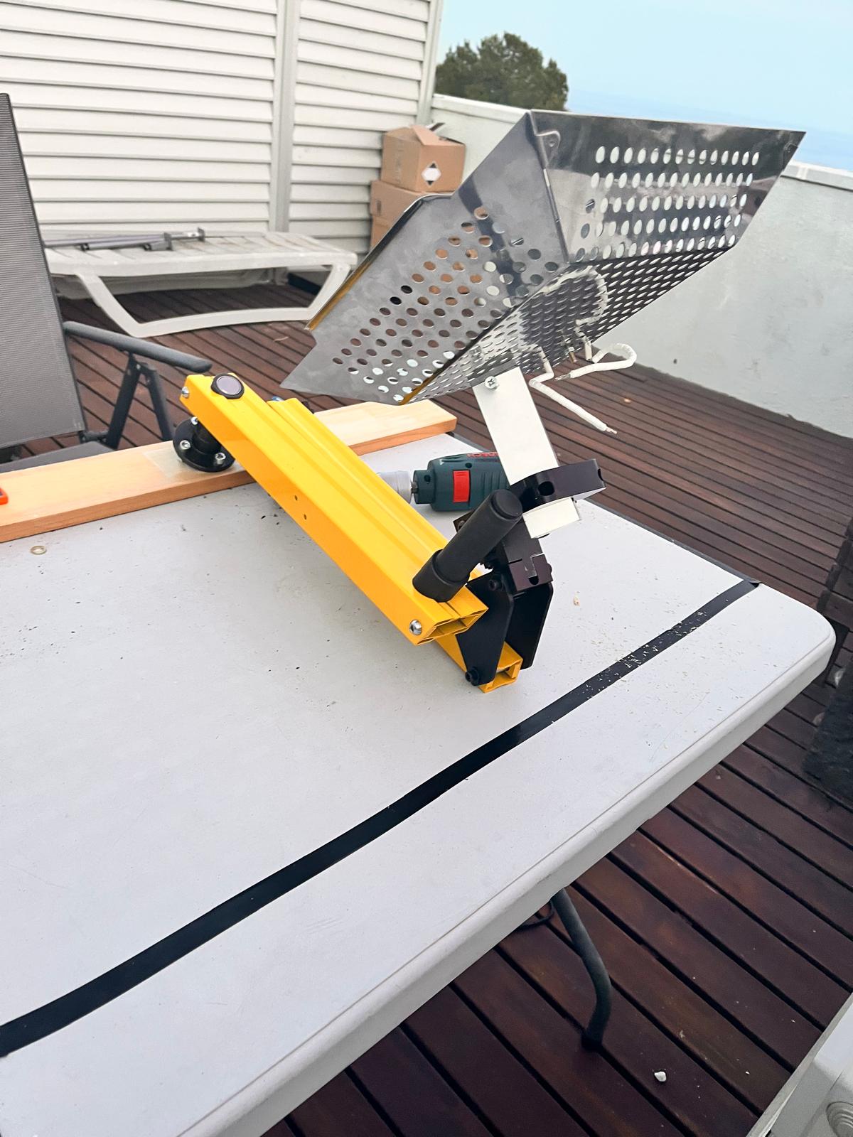
This was one of the first moments where ASFALT started feeling less like disconnected experiments and more like a coherent machine.
The articulated arm immediately introduced new variables:
- balancing the weight of the heating assembly
- controlling tilt angles
- structural flex under load
- movement range over a cooking surface
- accessibility for the operator
Testing Angles and Reach
After the first successful attachment, I continued experimenting with different arm positions and reflector orientations.
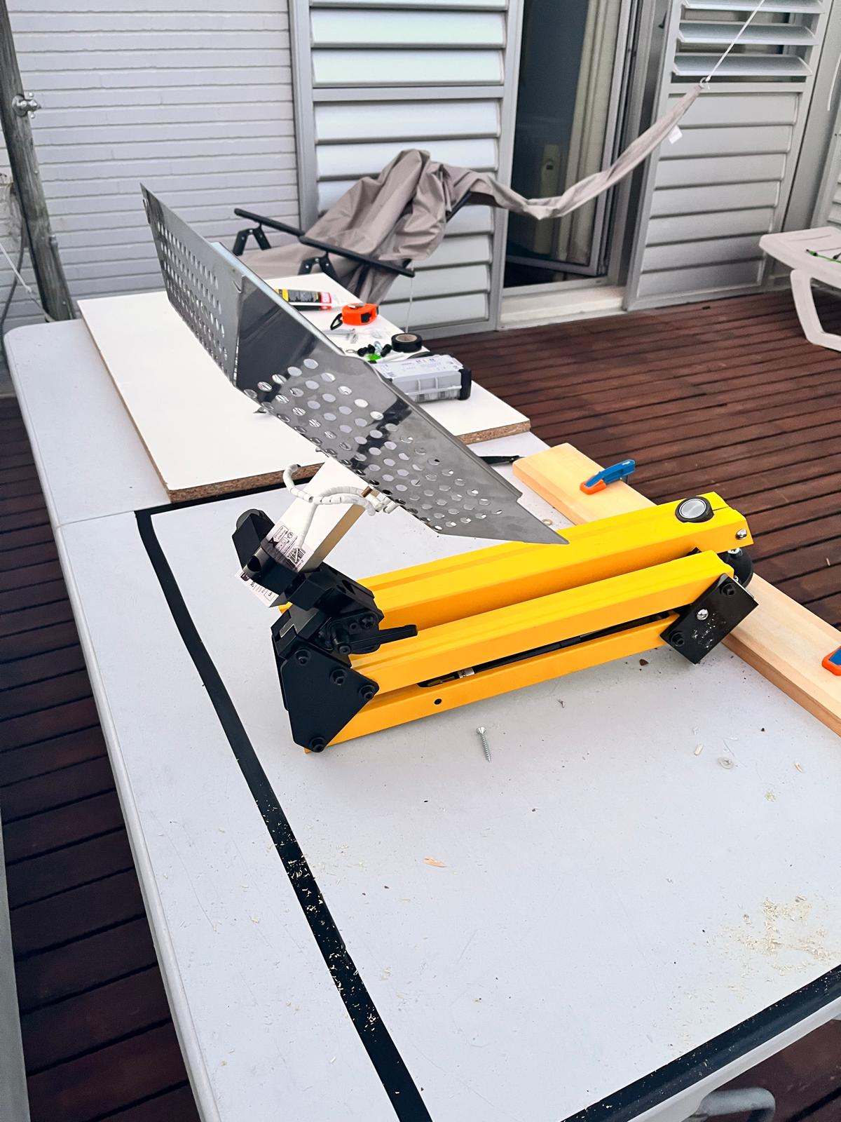
These quick tests helped evaluate:
- possible cooking positions
- visibility beneath the heater
- distance between heat source and surface
- mechanical stability while extended
- future operator interaction
The system was still rough and highly experimental, but physically moving the assembly revealed much more information than CAD alone.
Simplifying the Reflector Interior
As experimentation continued, I temporarily removed the heater module to evaluate the reflector geometry on its own.
Without the heater installed, it became easier to analyze:
- internal volume
- reflection surfaces
- mounting points
- cable routing possibilities
- future enclosure constraints
This also clarified that the reflector itself could become a more intentional fabricated component later, rather than simply an adapted tray.
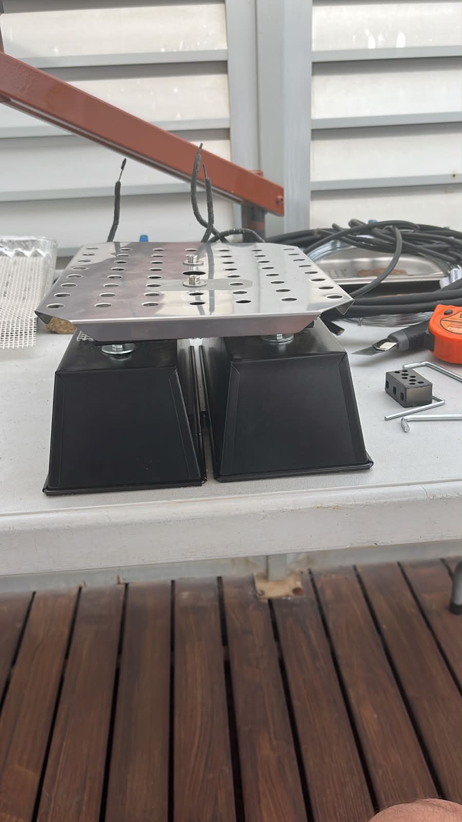
Evaluating the Heater Cassette Layout
With two heater units side-by-side, I could finally start evaluating spacing, proportions and module organization more realistically.
This helped visualize several future possibilities:
- interchangeable heating modules
- scalable heating width
- removable cassette systems
- independent thermal zones
- modular maintenance strategies
Even though the setup was rough, physically seeing multiple modules together made the system architecture much easier to imagine.
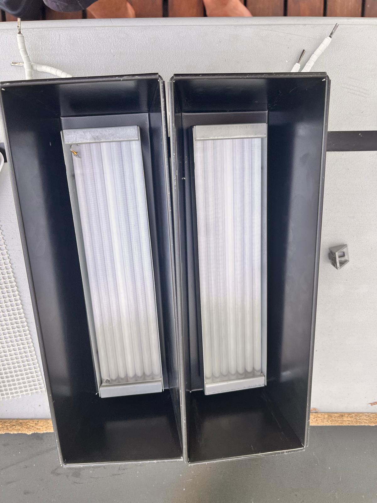
The black surfaces visually reduced the apparent bulk of the system and made the heating elements stand out more clearly.
At the end of these experiments I had several different cassette directions assembled simultaneously.
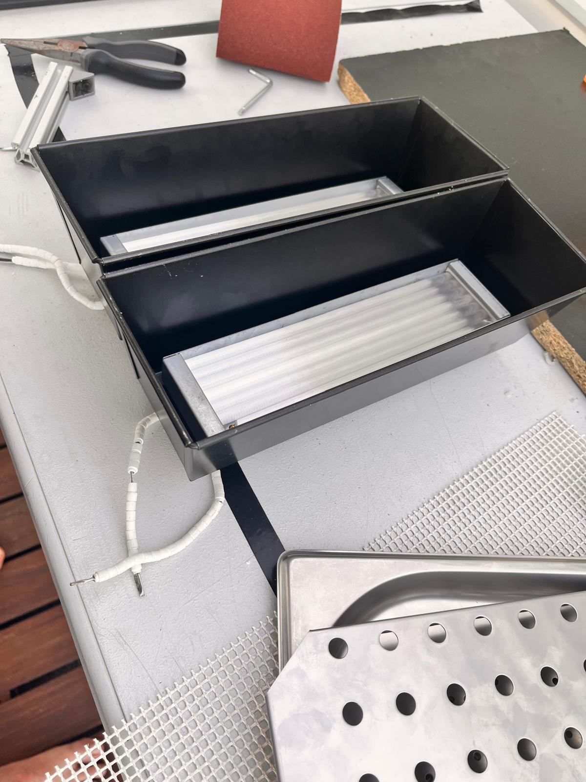
Seeing them side-by-side made it easier to compare:
- proportions
- manufacturability
- visual weight
- assembly complexity
- modular potential
Surface Finishing Experiments
At a later stage, I painted some of the heater housings and structural components black to reduce visual noise and begin testing a more unified aesthetic language.
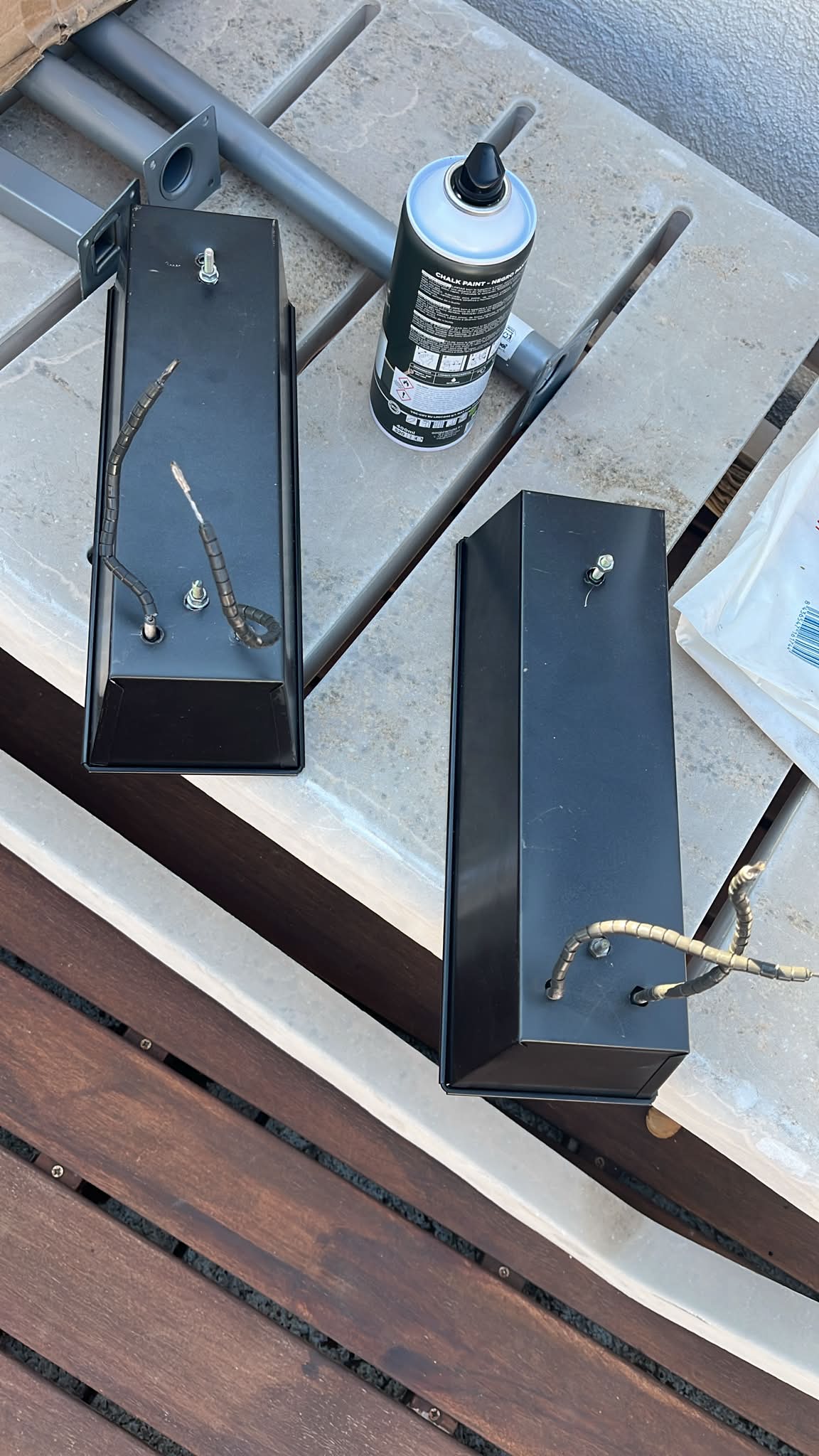
Even simple finishing work changed how the prototype was perceived as a system rather than a collection of random hardware.
Painting the arm for Asfalt color pallete
Once the structural interface was functional, I shifted attention toward coherence of the assembly and basic surface finishing.
The arm components were disassembled and painted to unify the visual language of the prototype while also testing how off-the-shelf industrial parts could be adapted into a more intentional system.
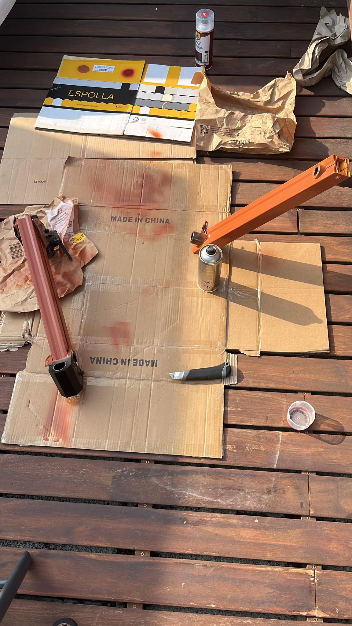
Although acrilic spray paint is not optimal, it ended up giving it a rusty, industrial, worn out feel that alligns well with the brand.
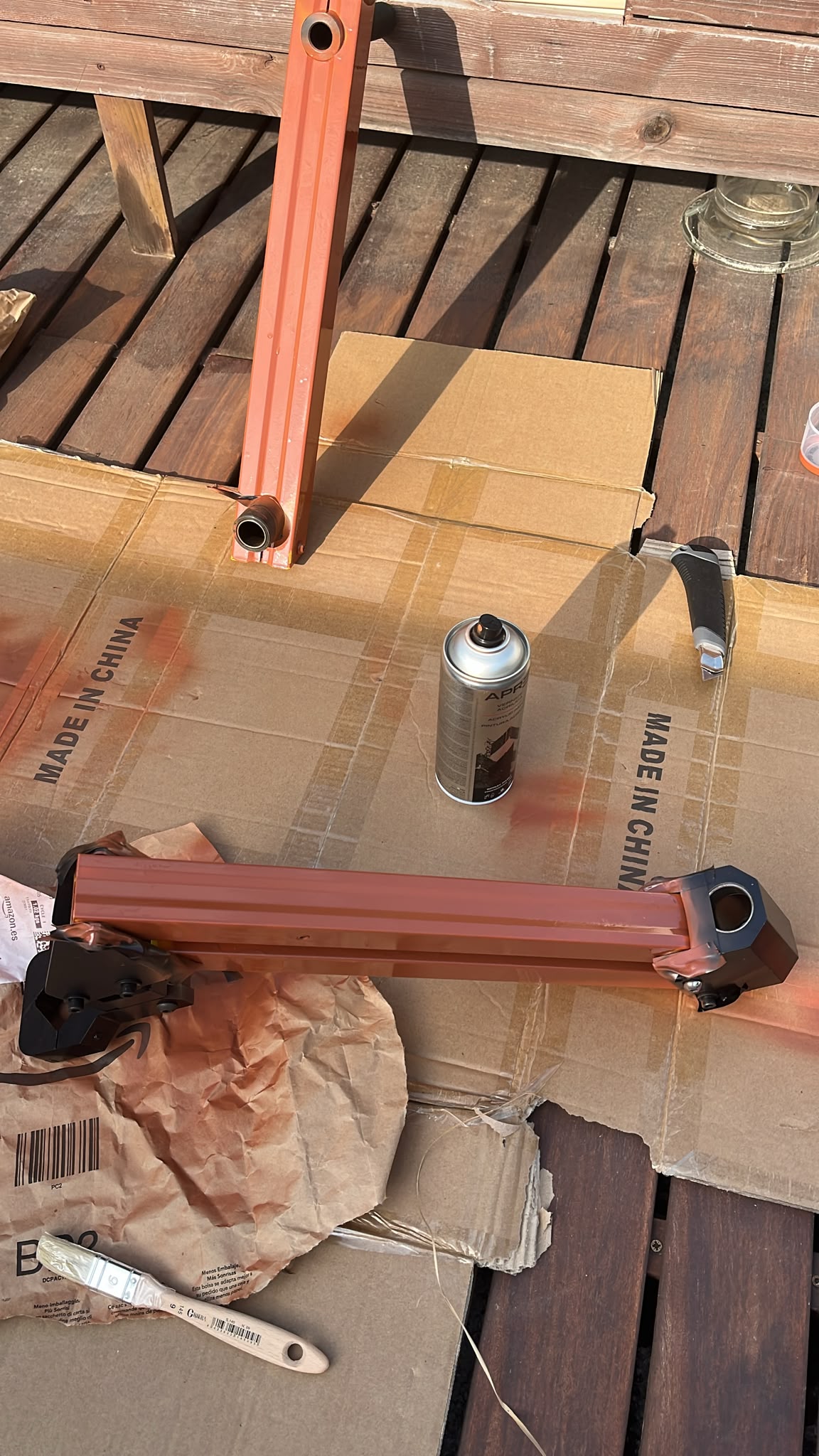
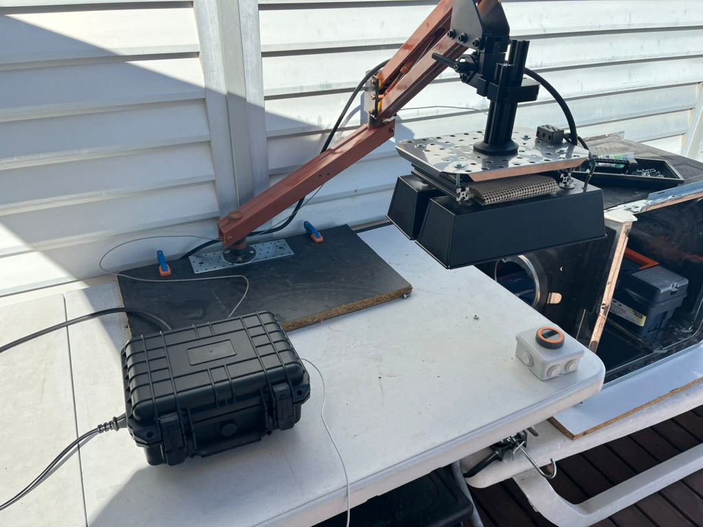
Final Arm Assembly
After reassembly, the articulated structure began behaving much closer to a functional subsystem rather than a collection of separate parts.
The integrated arm allowed exploration of:
- working height
- reach and positioning
- rotational movement
- mechanical stability
- future cable routing paths
- mounting possibilities for the heating dome
This was one of the first moments where ASFALT started transitioning from conceptual geometry into a physically integrated object.
Exploring Cassette Concepts Using Existing Food Service Components
At this stage I started exploring a different direction for the heating module enclosure.
Instead of building everything from scratch immediately, I experimented with adapting existing stainless steel food service equipment already designed for heat, cleaning and kitchen environments.
The idea was simple:
- reuse industrial geometries already optimized for kitchens
- reduce fabrication complexity
- prototype faster
- understand useful proportions and edge details
- test whether modular “cassette” assemblies could emerge from off-the-shelf parts
This became a very practical exercise in observing how much value already exists inside commercial kitchen hardware.
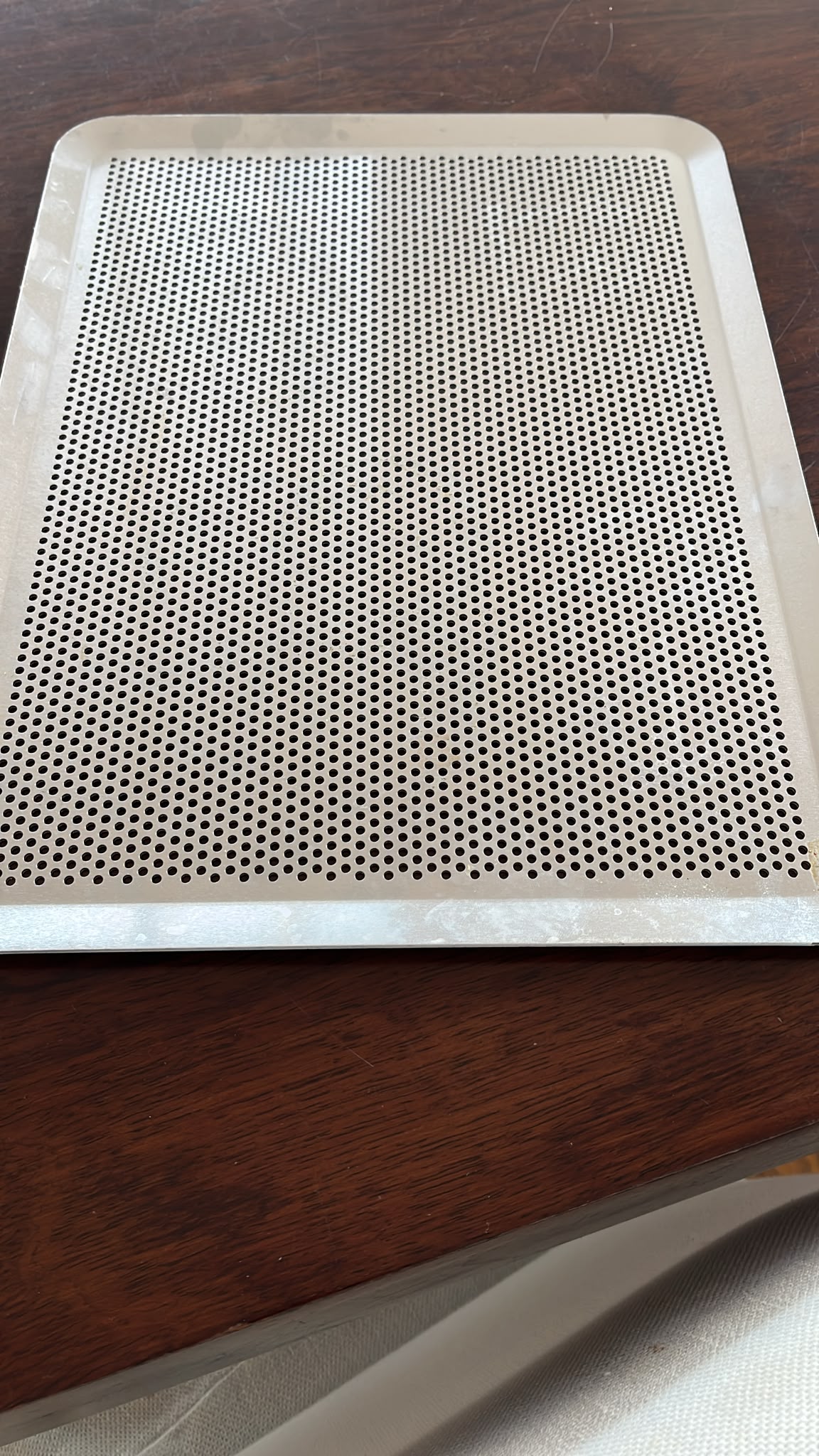
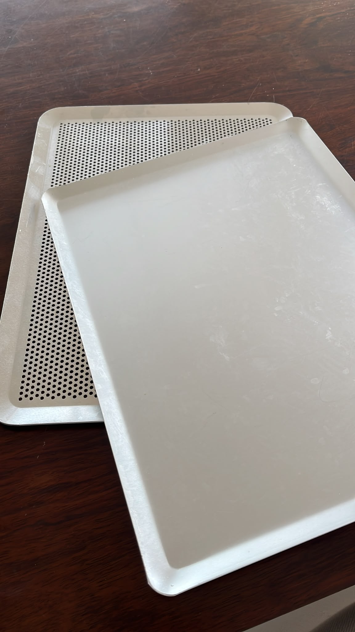
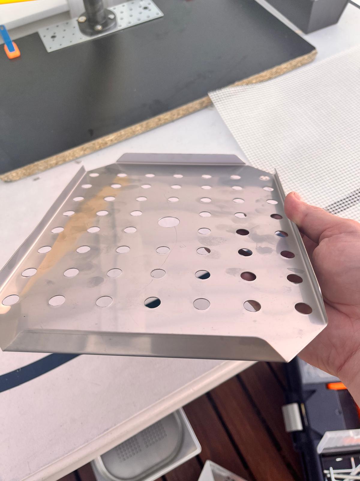
Looking at Existing Tray Geometries
I started by comparing several stainless steel trays and perforated pans commonly used in food preparation equipment.
The folded edges immediately stood out as useful structural features. Even very thin stainless steel became surprisingly rigid once bent into shallow tray geometries.
This was interesting for ASFALT because it suggested that:
- enclosure stiffness could come from geometry instead of thickness
- folded sheet metal could reduce weight significantly
- shallow trays already resembled possible heater cassettes
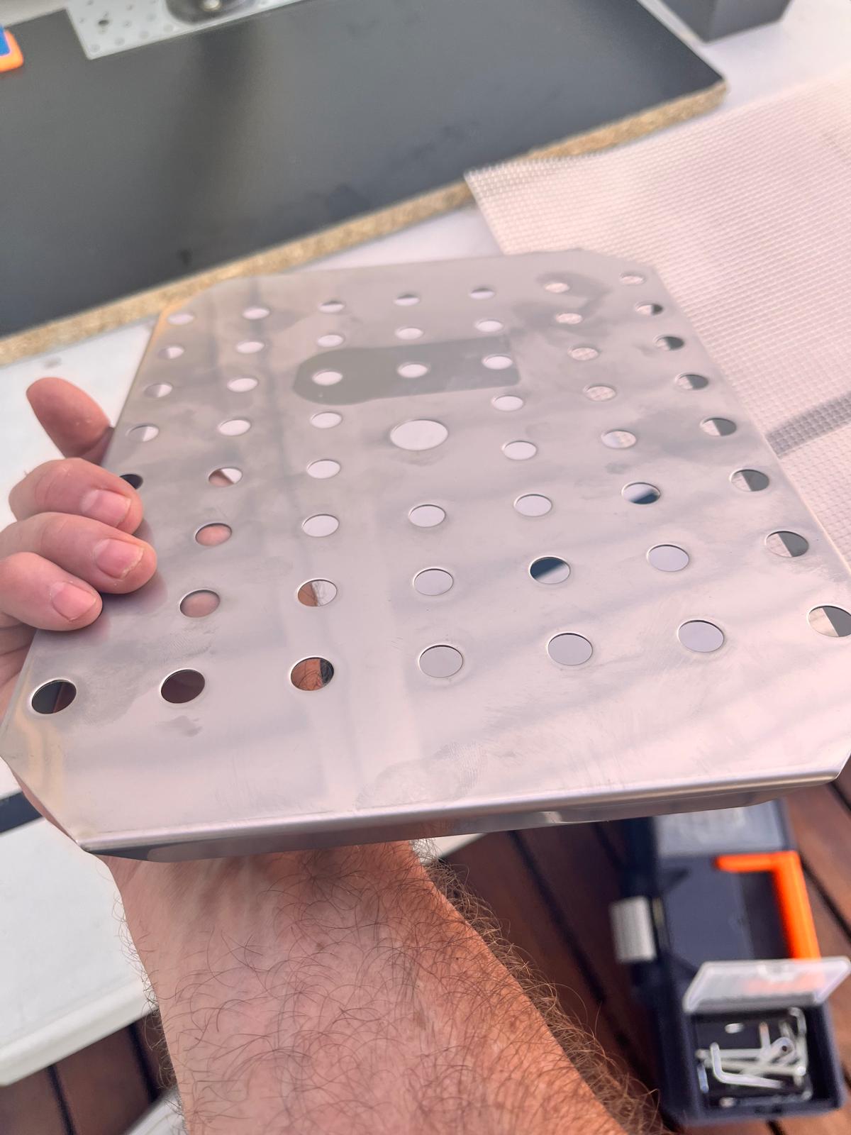
Comparing Solid and Perforated Surfaces
I also compared fully closed trays with perforated versions.
The perforated surfaces were especially interesting because they introduced:
- airflow possibilities
- mounting opportunities
- reduced weight
- visual transparency
- thermal venting behavior
At this point I still did not know whether the final cassette should be fully enclosed or partially open, so testing both options physically helped clarify the tradeoffs much faster than sketching.
Studying Folded Edge Profiles
After selecting a promising perforated tray, I started modifying it to test mounting possibilities. I spent some time simply observing the edge geometry and manufacturing logic of these trays.
The stamped and folded transitions revealed several useful fabrication ideas:
- rounded corners improve rigidity
- continuous folds eliminate many fasteners
- shallow depth creates lightweight stiffness
- standard kitchen manufacturing techniques are extremely optimized
This reinforced the idea that ASFALT should probably embrace industrial kitchen fabrication logic rather than fighting against it.
Another important observation came from looking at the tray profile from the side.
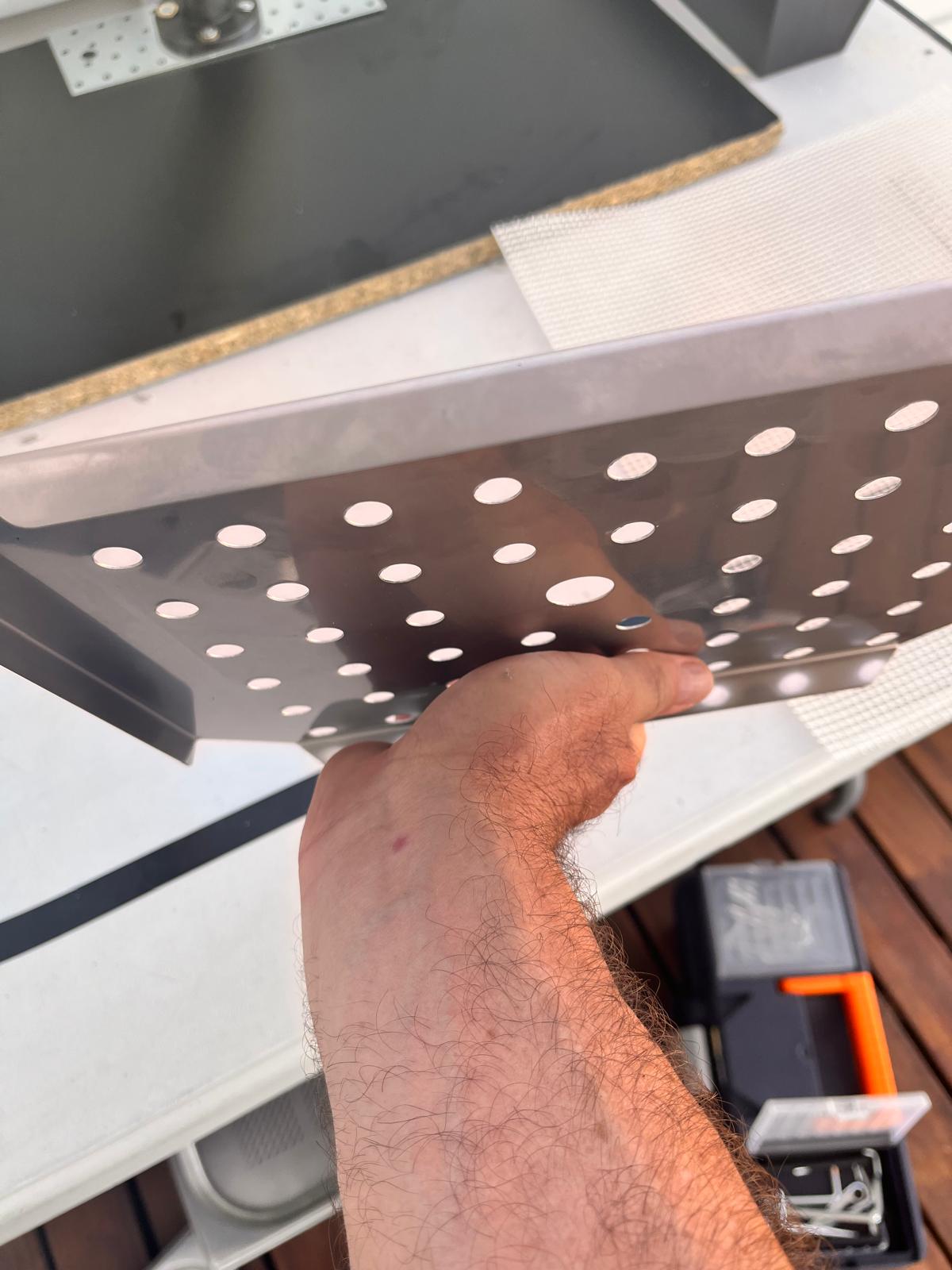
Even with thin material, the folded perimeter created enough rigidity to support handling and attachment without major deformation.
This small detail became important because it suggested that future ASFALT modules could potentially use:
- lightweight folded stainless steel shells
- removable cassette architectures
- simplified laser-cut and bent fabrication workflows
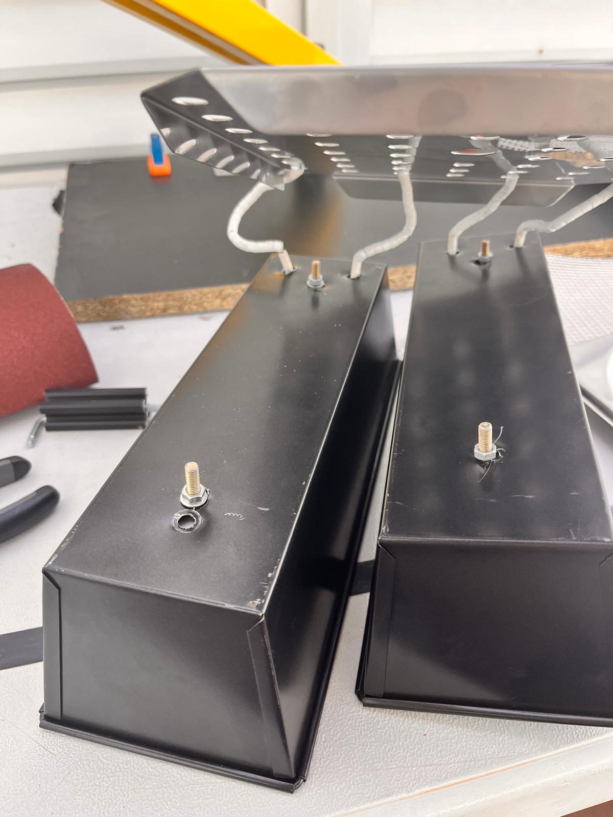
Connecting the Cassette to the Heater Bodies
Once the tray geometry felt promising, I began attaching it to the black heater housings.
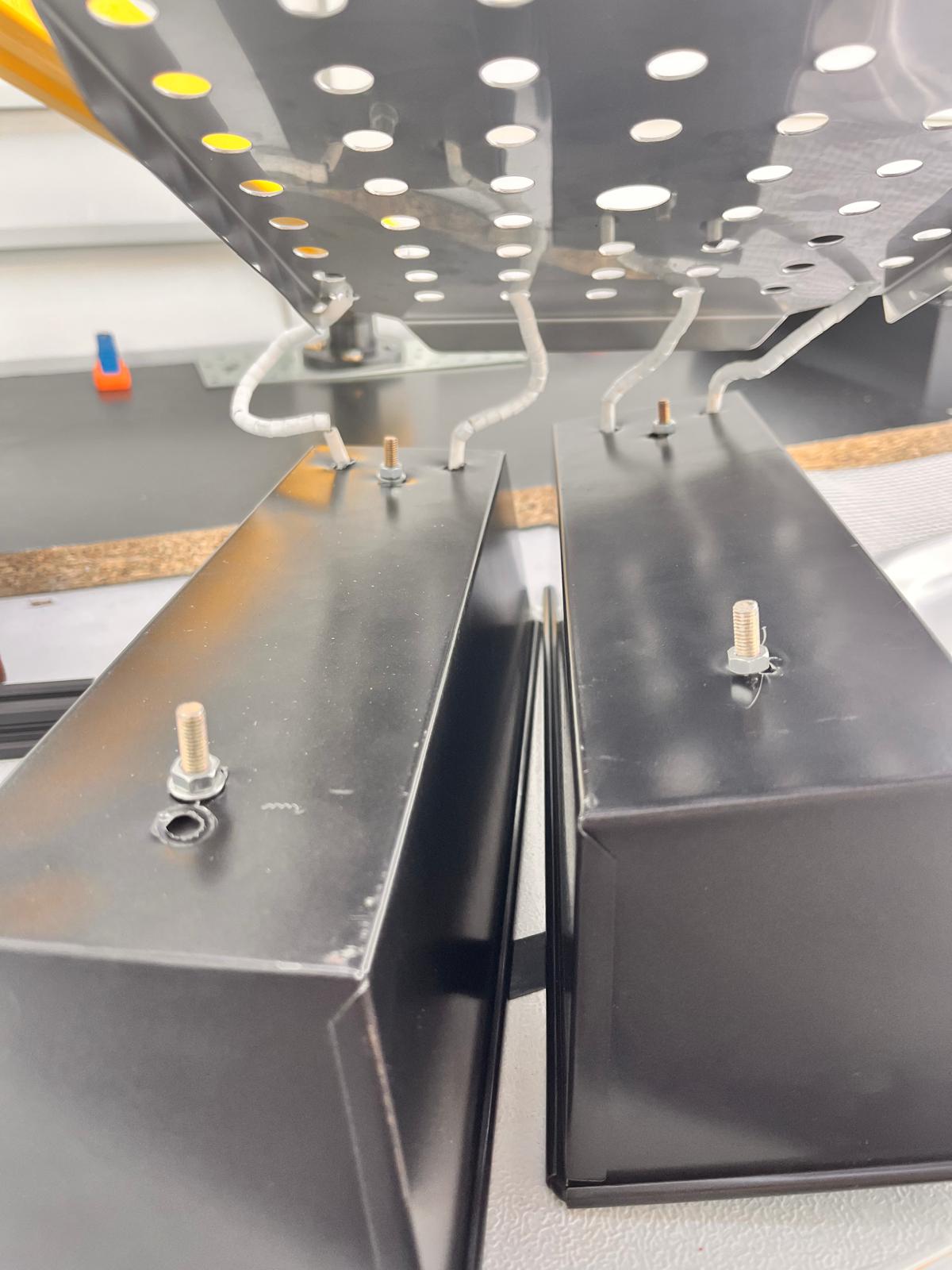
This was one of the first moments where the cassette idea started feeling physically coherent.
The assembly started behaving less like separate components and more like a modular subsystem composed of:
- reflective upper structure
- heater body
- mounting layer
- structural attachment points
The relationship between these layers became much clearer once physically stacked together.
Underside Attachment Experiments
I also explored how the reflector tray could mechanically attach underneath while still allowing cable routing and future maintenance access.
This phase involved a lot of trial-and-error positioning of:
- spacers
- screws
- cable exits
- alignment points
- heater orientation
One recurring challenge was balancing:
- structural rigidity
- clean assembly
- serviceability
- thermal separation
Exploring Aluminum T-Slot Structures
After experimenting with sheet metal trays and cassette geometries, I started investigating aluminum T-slot profiles as a possible structural system for ASFALT.
The goal was to evaluate whether modular aluminum extrusion systems could help solve several recurring problems simultaneously:
- adjustable positioning
- rapid prototyping
- modular assembly
- removable heating cassettes
- easier maintenance
- scalable structure development
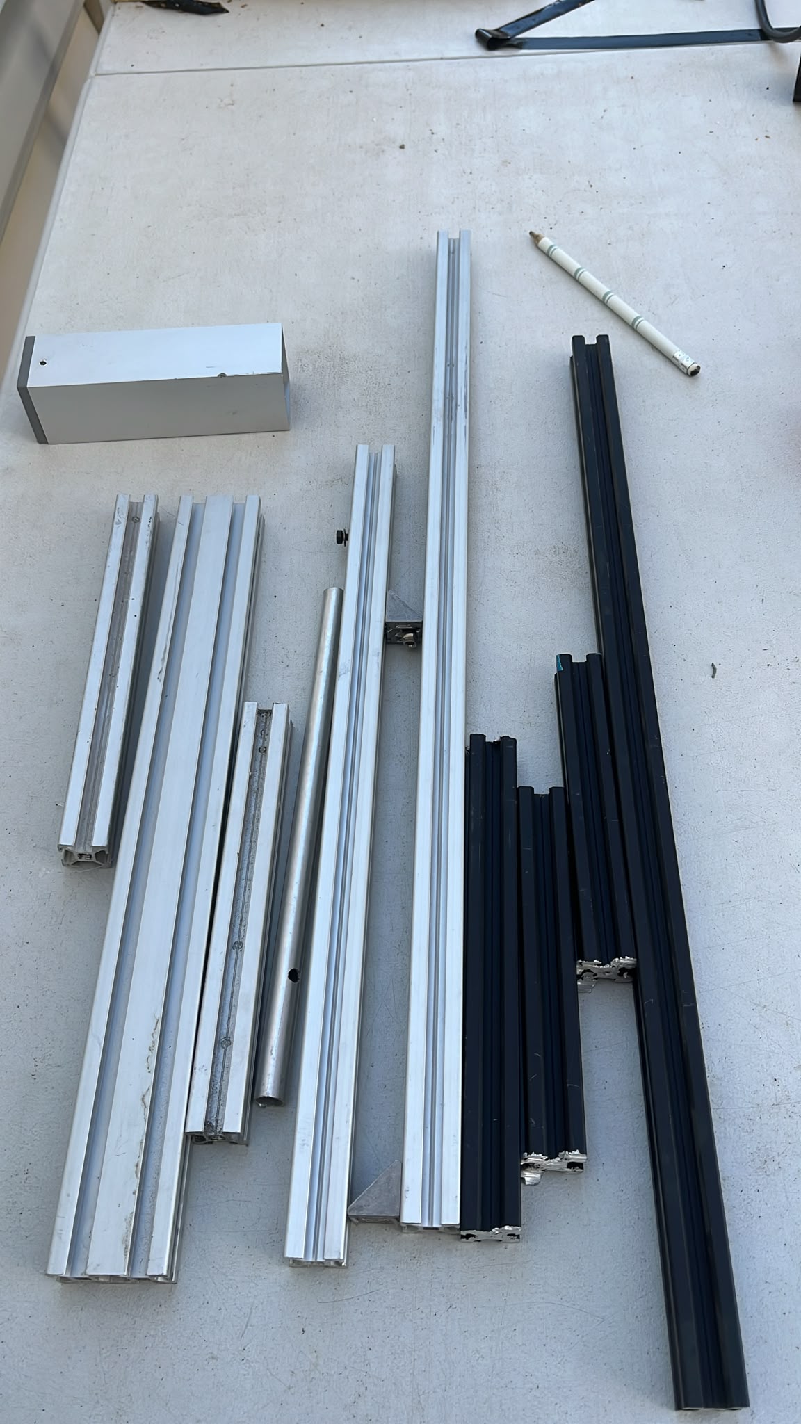
I gathered different sized of the aluminum profiles from the Lab to test them out and play around with them.
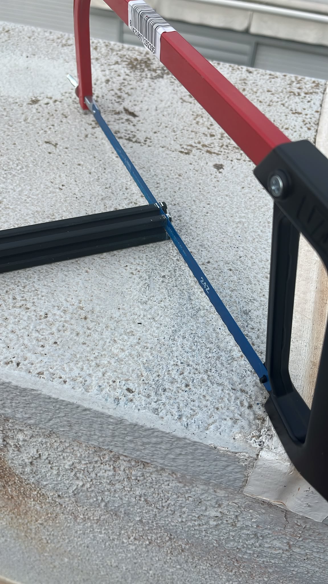
Manual Fabrication Process
The first step was learning how manageable these profiles were using simple tools.
I tested manual cutting using a small hacksaw.
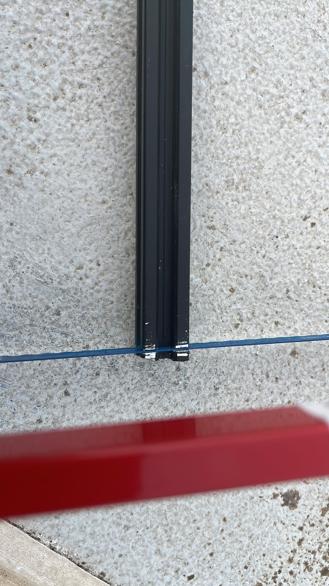
The profiles cut relatively easily, although maintaining perpendicular cuts required care.I also tested longer cuts and basic workshop handling.
One useful observation was that aluminum extrusion systems dramatically reduce fabrication uncertainty compared to fully custom welded structures.
Instead of designing every bracket from scratch, many structural decisions become configurable during assembly.
This experiment clarified several practical fabrication realities:
- aluminum extrusions are accessible without industrial machinery
- cuts can be made quickly during iterative prototyping
- tolerances become important for clean joints
- burr removal is necessary after cutting
After cutting the extrusion, I examined the internal profile structure more carefully.
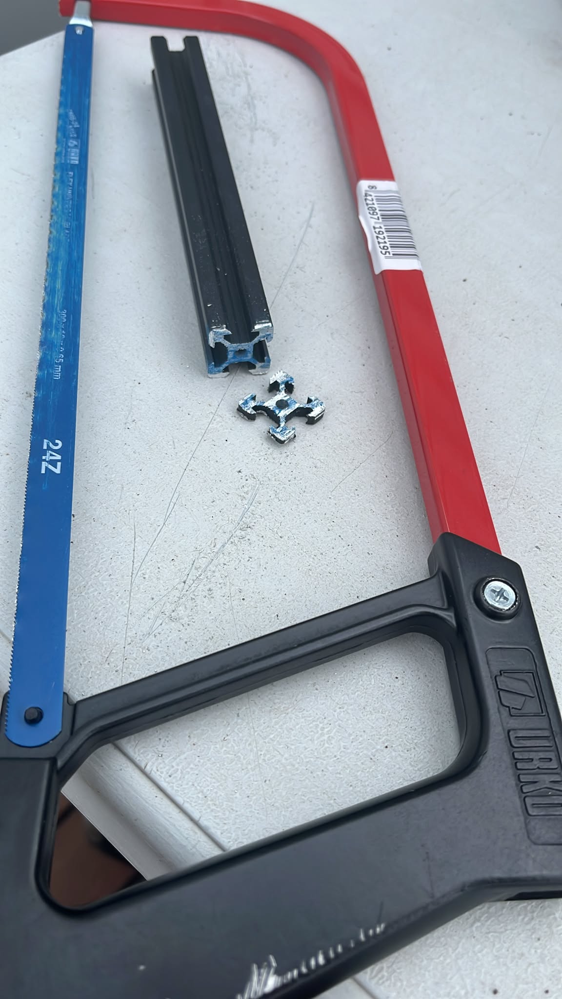
The cross-section revealed why these systems are so versatile:
This was important for ASFALT because it suggested that structural experimentation could happen very quickly without fully redesigning every joint.
Testing Structural Integration with the Heater Module
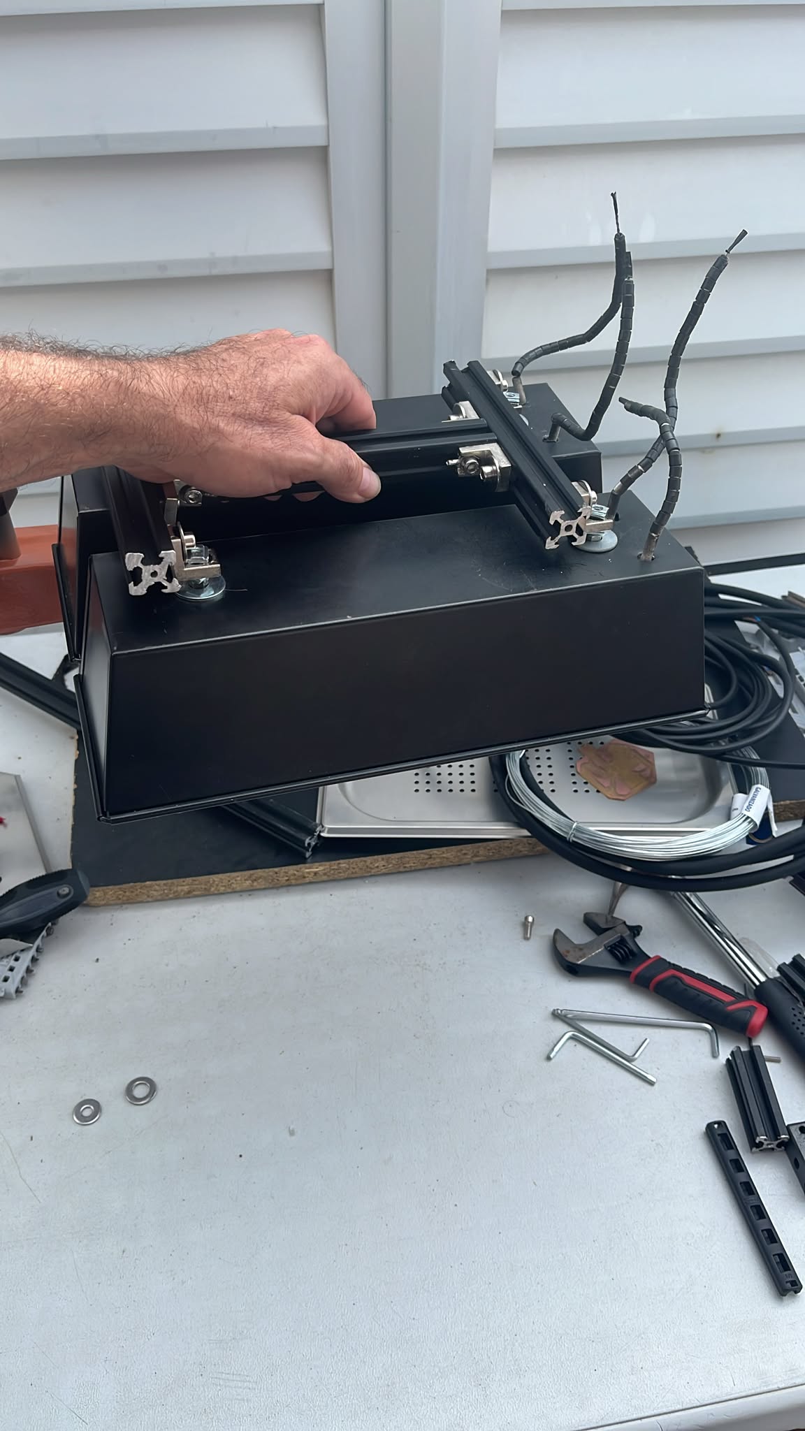
Once several profile sections were prepared, I began integrating them with the heater cassette prototypes.
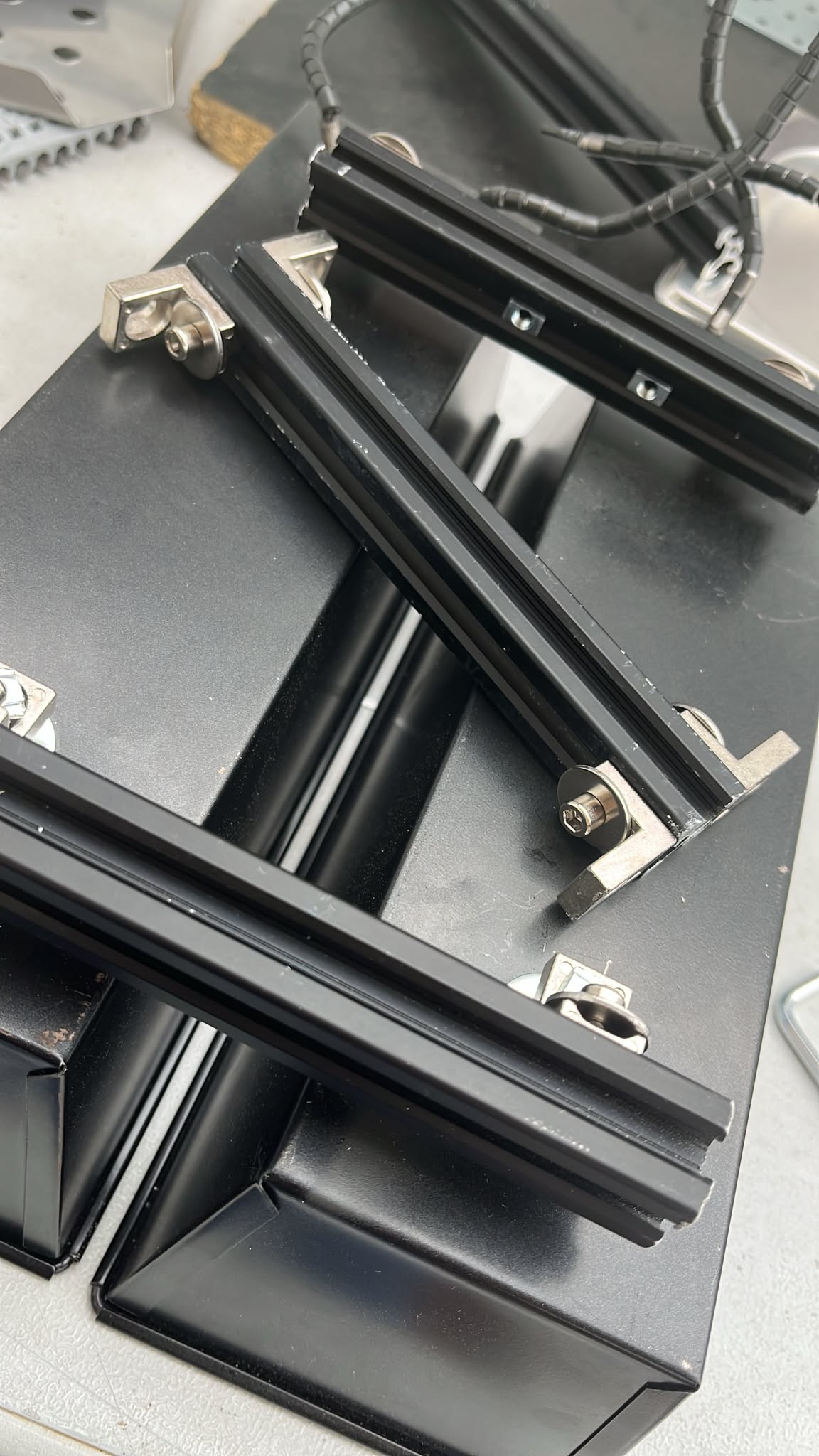
This immediately introduced several new possibilities:
- adjustable mounting height
- sliding positioning systems
- removable heater assemblies
- modular service access
- future expansion of the structure
Compared to fixed sheet metal assemblies, the T-slot system behaved more like a configurable mechanical platform.
Exploring Joint Configurations
I experimented with multiple connection methods between the profiles and the reflector body.
This stage was especially valuable because it exposed several hidden constraints:
What worked well
- rapid alignment adjustment
- reusable hardware
- strong structural rigidity
- modular assembly logic
Problems encountered
- connection hardware adds visual complexity
- fasteners accumulate quickly
- exposed joints may trap grease and dirt
- profile dimensions influence overall product aesthetics
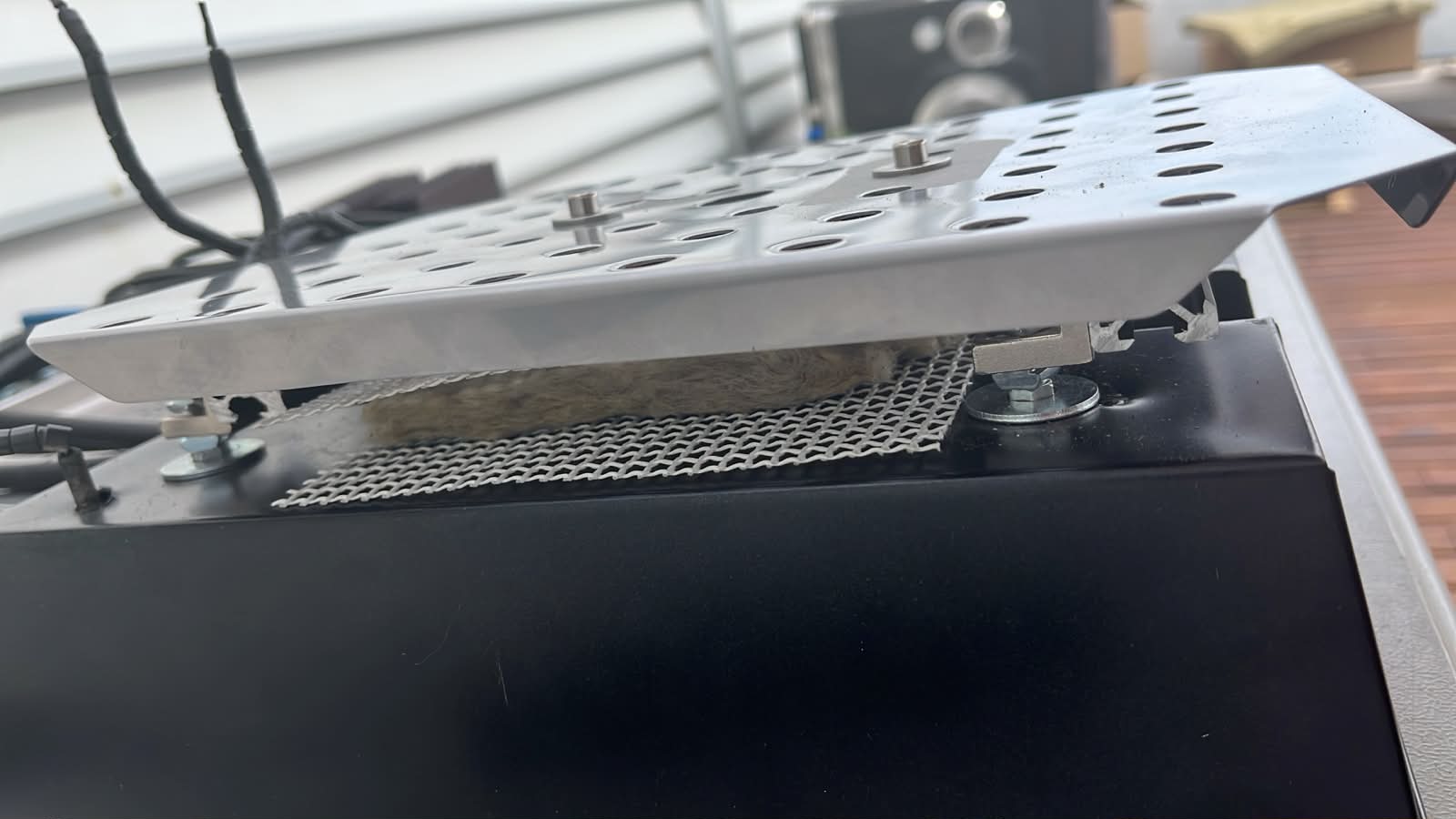
Adding Insulation
After validating the aluminum T-slot structure, I moved into thermal insulation experiments by adding rockwool inside the cassette assembly.
Rockwool is commonly used in professional ovens because of its ability to resist high temperatures while reducing heat transfer to surrounding structures. I wanted to explore this same principle inside ASFALT to better understand how heat could be contained, controlled, and separated from the structural frame.
The first tests involved placing loose rockwool between the aluminum profile rails.
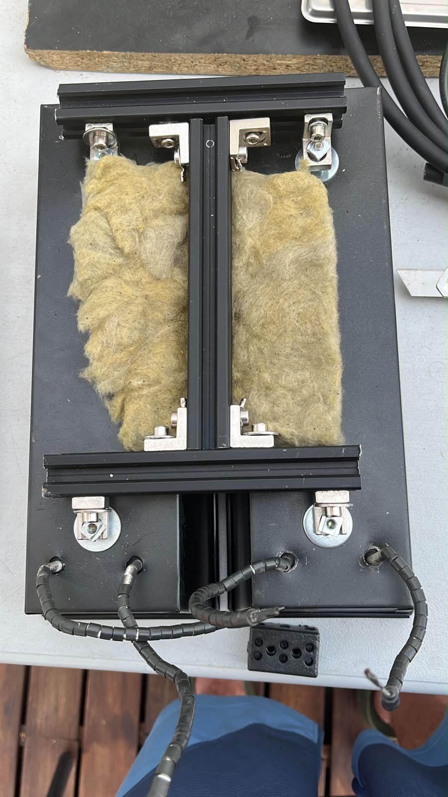
The material immediately showed strong thermal potential. It naturally filled the cavities created by the T-slot structure and created a clear thermal barrier between the heating area and the external enclosure. The experiment also helped visualize how commercial cooking equipment often relies on layered thermal construction rather than only thick metal walls.
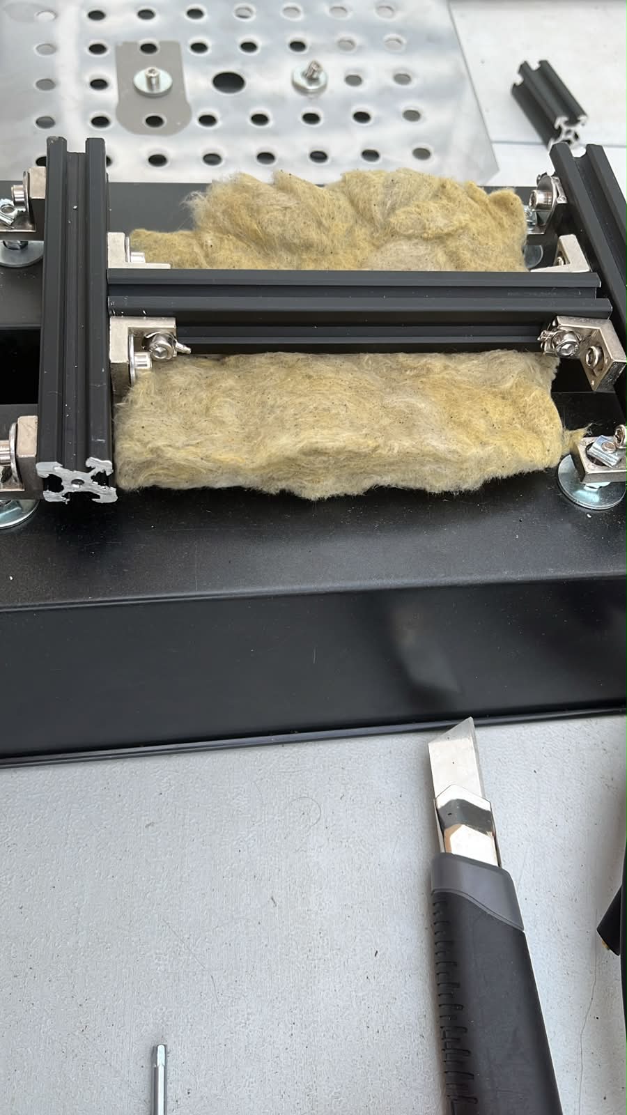
I then experimented with compressing the insulation inside the structure to study how much material could fit within the available cavity space.
This revealed an important architectural insight: the aluminum extrusion system was not only acting as a structural frame, but also as a natural insulation support system. The rails automatically generated channels and compartments where thermal material could be inserted without needing additional custom parts.
One issue quickly became obvious: loose insulation fibers would not be suitable for a real food-service product. Handling the assembly disturbed the material, and exposed fibers could become problematic for cleanliness, maintenance, and long-term durability.
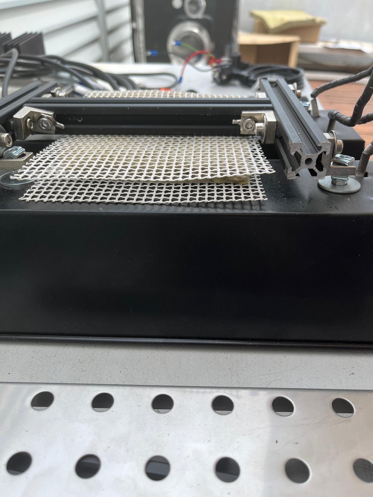
To address this, I added a mesh retention layer over the rockwool.
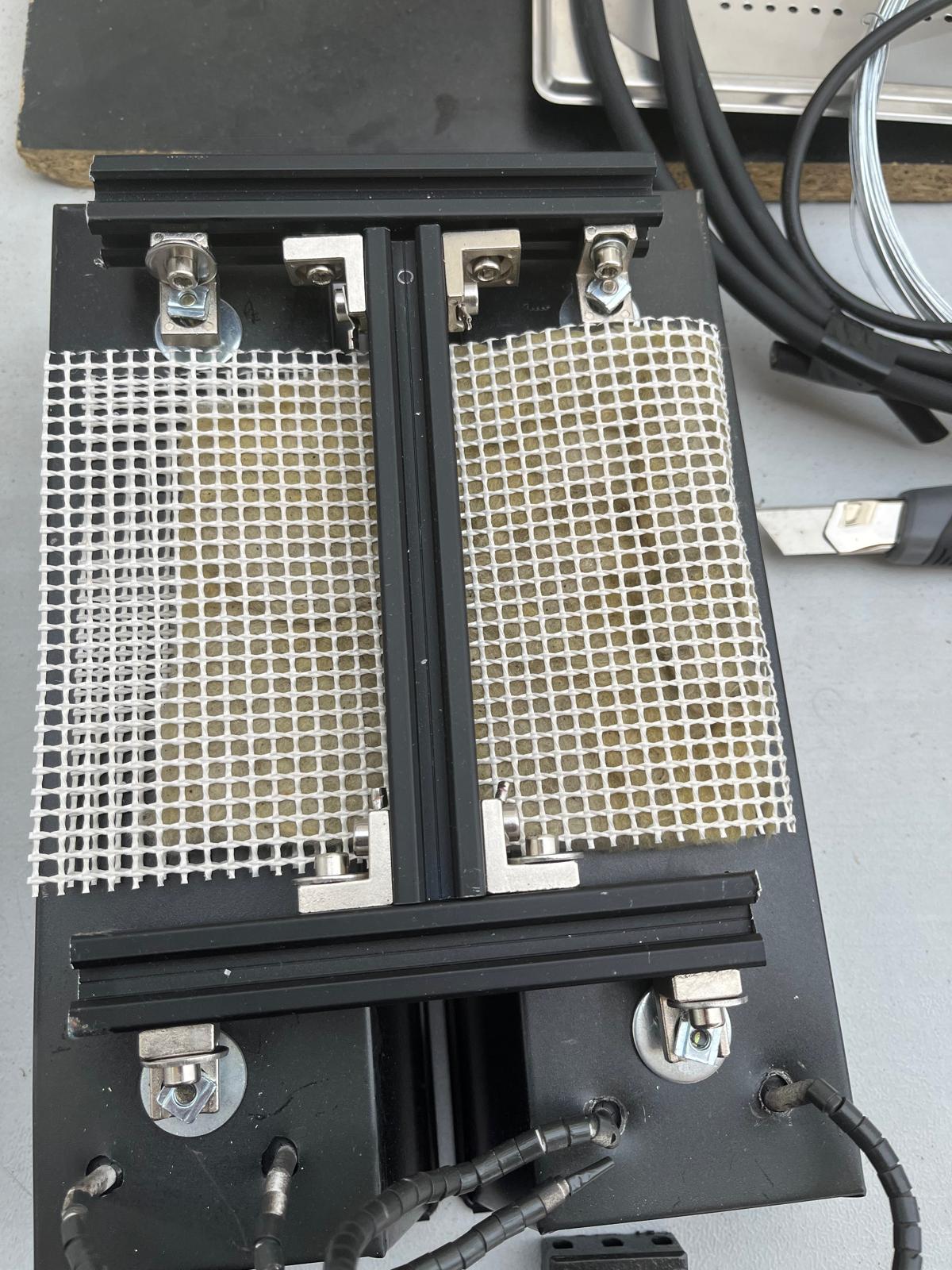
This simple addition dramatically improved the assembly. The insulation became mechanically contained, easier to handle, and visually closer to how professional thermal equipment is built.
The layered structure also started to feel more coherent from an engineering perspective:
- external enclosure
- aluminum structural frame
- rockwool insulation
- retention mesh
- radiant heating components
The cassette was starting to evolve into a layered thermal system similar to commercial ovens and professional heating appliances, where structure, insulation, airflow, and radiation all work together rather than as isolated components.
Integrating the Top Tray into the Thermal Cassette
The final step of the cassette prototype was integrating the perforated stainless steel top tray with the insulation and reflective layers to create a complete thermal assembly.
The stainless steel tray became the upper thermal interface of the system. Its role was no longer only structural; it also acted as:
- a radiant reflection surface
- a mounting plane for heating components
- an airflow and ventilation layer
- a thermal separation skin between the heat source and the exterior
The tray was mounted above the insulated cavity using aluminum T-slot spacers. This created a controlled air gap between the reflective surface and the insulation below.
This gap became important because it introduced another thermal management strategy commonly used in professional ovens and industrial heating systems: layered thermal separation.
Instead of relying on a single insulating material, the cassette now combined:
- reflective stainless steel
- air gap
- rockwool insulation
- lower enclosure structure
This multi-layer arrangement helps slow conductive heat transfer while also reflecting radiant energy back toward the cooking area.
The perforated surface introduced another useful behavior.
The holes reduced overall material mass while potentially allowing controlled airflow and thermal expansion. The geometry also visually reinforced the industrial appliance language that ASFALT is exploring.
During assembly, the aluminum extrusion was inserted directly through the top plate to act as a structural connector and future mounting interface.
This detail became particularly important from a systems design perspective because the same structural element could simultaneously from rear and from the top part.
The ceramic terminal block and high-temperature insulated wiring were then positioned onto the tray to begin studying how electrical integration could coexist with the thermal architecture.
The final assembly started to resemble a compact professional heating cassette rather than a collection of prototype parts.
The cassette architecture was becoming modular, serviceable, thermally layered, and mechanically adjustable.
Console integration
This week focused on integrating the various electronic and control subsystems developed throughout the course into a single portable control console for ASFALT.
The objective was to build a robust enclosure capable of:
- housing the controller electronics
- switching mains power safely
- interfacing with external heating modules
- connecting temperature sensors
- supporting future upgrades
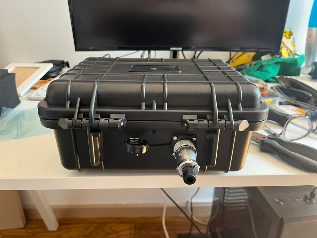
The result was the first complete ASFALT control console.
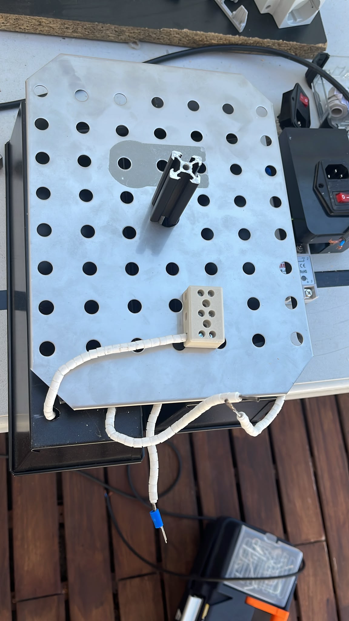
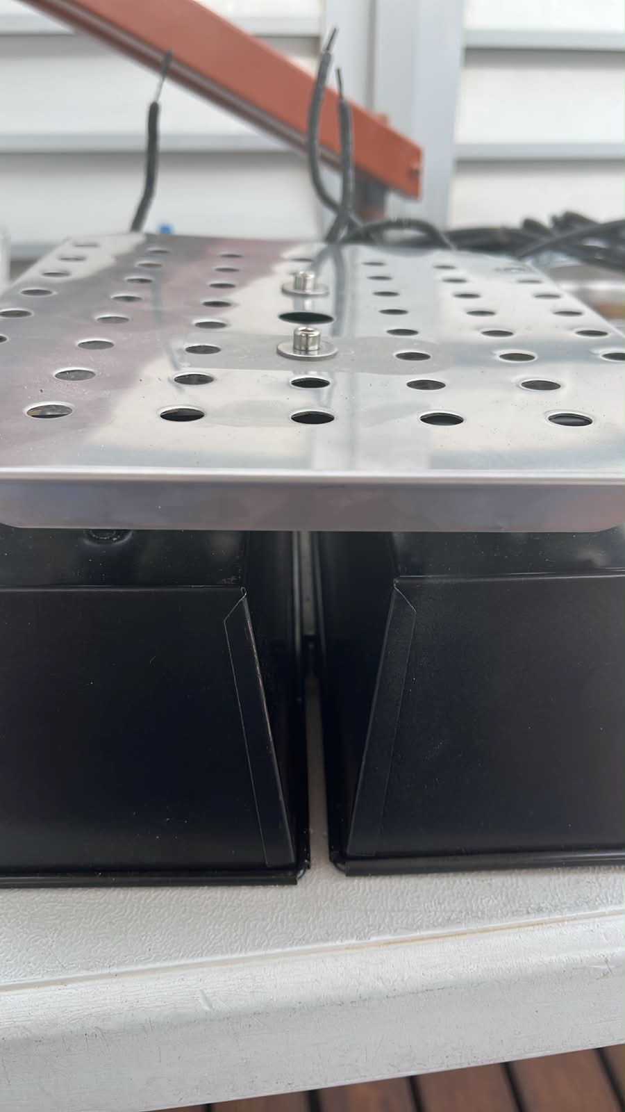
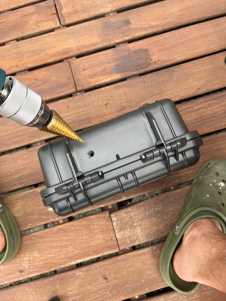
Rugged Portable Enclosure
A waterproof hard case was selected as the enclosure due to its robustness, portability and ability to isolate the electronics from kitchen environments.
The enclosure provides:
- physical protection
- cable management
- environmental resistance
- transportability between tests
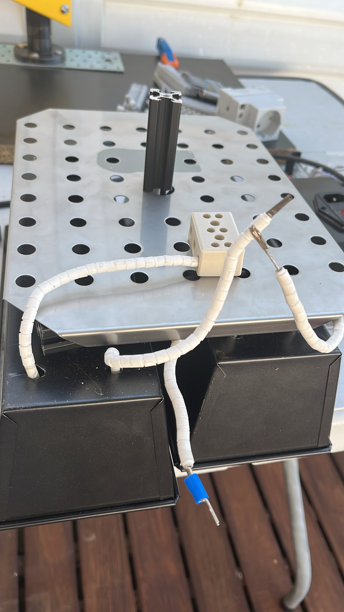
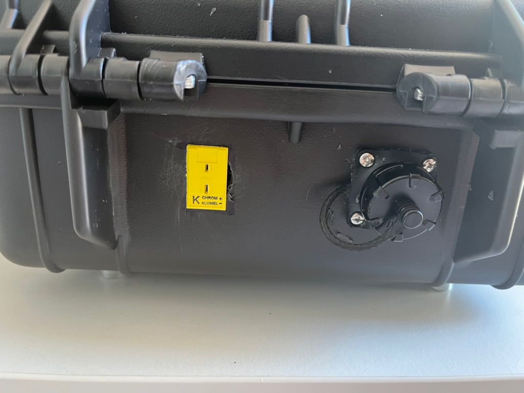
External Interfaces
The control box was designed around the idea that heating modules should remain external and interchangeable.
This required external connections for:
- heater output
- thermocouple input
- power input
- future communication interfaces
Panel mounted connectors were installed to avoid opening the enclosure during operation.
Heater Connection
A locking aviation connector was selected as the primary heater output connection.
This connector provides:
- secure locking during operation
- quick heater replacement
- improved strain relief
- protection against accidental disconnection
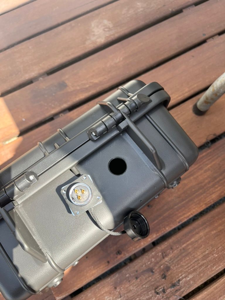
Once installed, the connector became the main interface between the control console and the heating module.
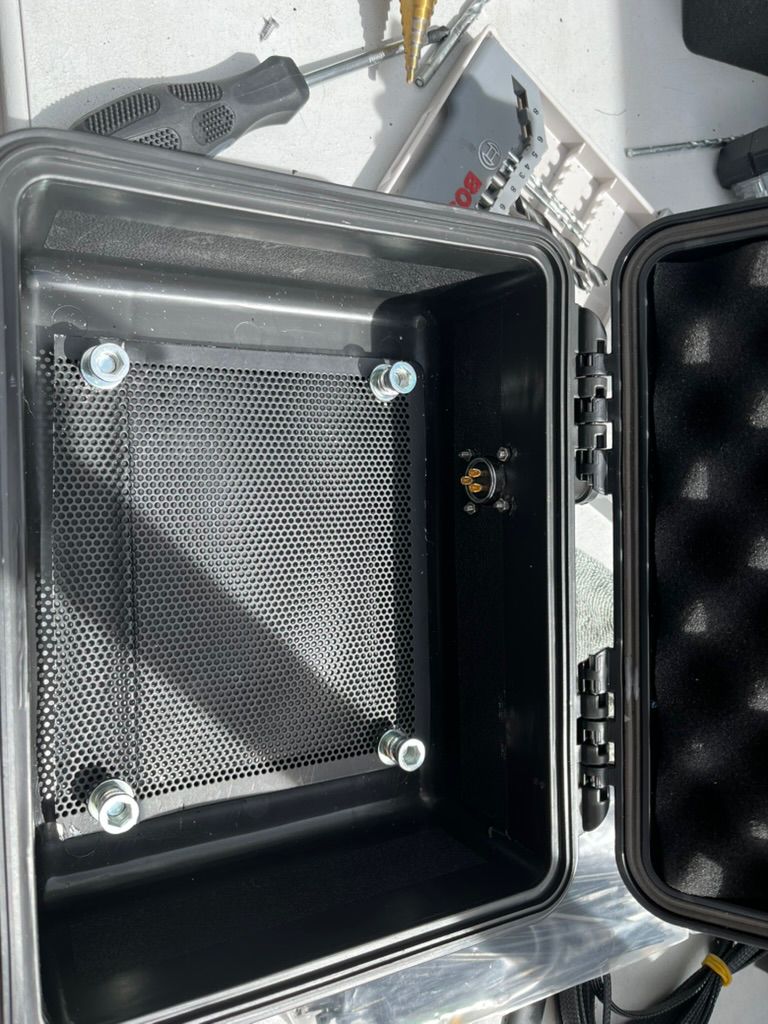
Thermocouple Interface
Temperature measurement was externalized using a panel mounted K-type thermocouple connector.
This allows different probes to be connected depending on the experiment:
- surface measurements
- reflector measurements
- heater measurements
- food measurements
Internal Structure
A perforated metal plate was installed inside the enclosure to act as a mounting surface for the electronic components.
The plate provides:
- mechanical support
- airflow below components
- modular repositioning
- grounding opportunities
The use of standoffs also creates additional thermal separation from the enclosure itself.
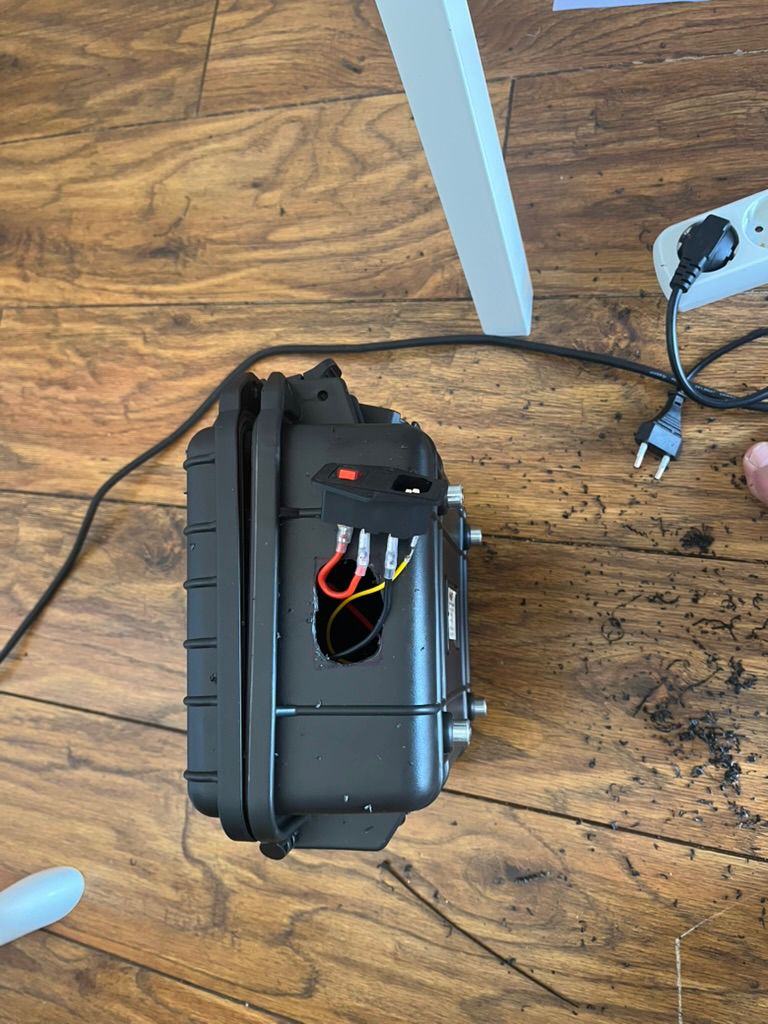
Power Entry
An IEC power connector was installed to simplify mains power integration and allow the use of standard computer power cables.
This decision improved:
- portability
- serviceability
- replacement availability
- testing convenience
Power Electronics Integration
The first integrated version combined:
- solid state relay
- controller board
- mains distribution
- low voltage supply
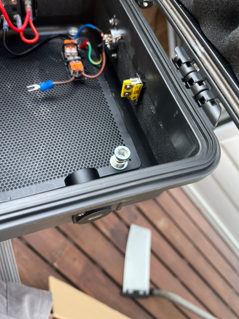
The SSR became responsible for switching the heating element while maintaining electrical isolation from the controller.
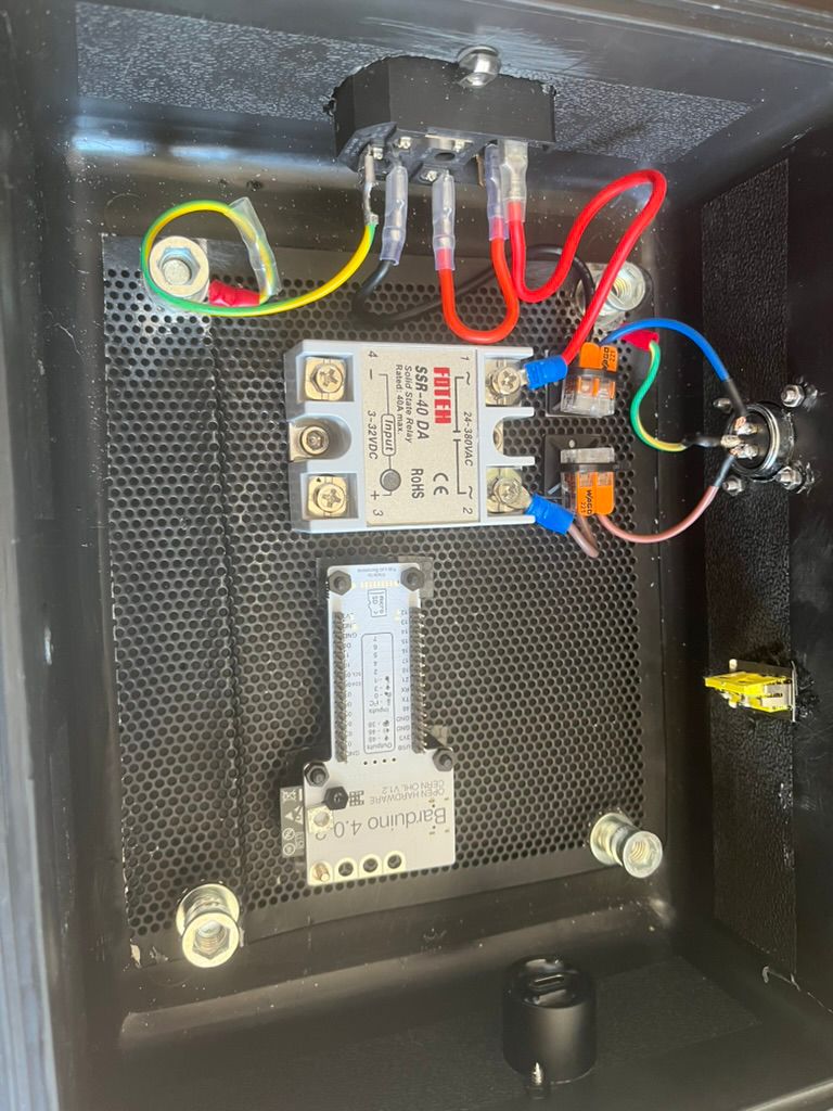
Controller Integration
As development progressed the Barduino controller, thermocouple interface and low voltage power supply were integrated into the enclosure.
This produced the first fully functional thermal control system capable of:
- reading temperature
- receiving operator input
- calculating control actions
- switching heater power
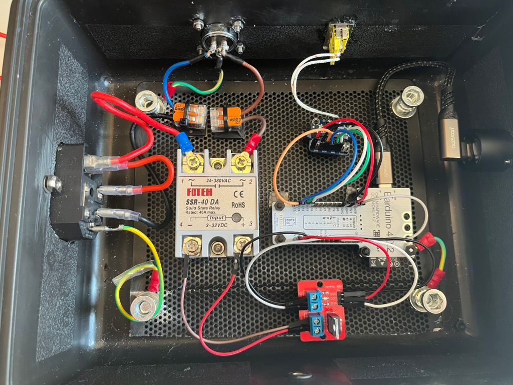
First Integrated Prototype
The completed console became the central hub connecting all ASFALT subsystems:
- M5Dial user interface
- Barduino controller
- thermocouple feedback
- SSR switching
- external heating module
This represented the first moment where the complete control loop existed as a physical system rather than a collection of independent prototypes.
ASFALT Translation
This week transformed ASFALT from individual subsystems into a complete thermal control architecture.
The console established:
- a modular electronics platform
- safe mains switching
- external heater compatibility
- interchangeable sensor support
- portable deployment for future testing
Although temporary and intentionally overbuilt, the console provides a stable platform for thermal experiments and future iterations of the project.
Learnings
This process was very iterative and physical. Most decisions came from directly handling the objects, combining parts and observing unexpected relationships between geometry, structure and heat management.