Week 09 — Input Devices
Global Class
This week focuses on how physical phenomena are captured and translated into digital signals that a microcontroller can process. It builds directly on the previous week, where a working PCB was fabricated, and introduces the sensing layer required for interaction and control.
Types of Inputs
Microcontrollers receive input through different mechanisms:
-
Digital inputs
-
binary signals (HIGH / LOW)
-
buttons, switches
-
Analog inputs
-
continuous voltage signals
-
read using ADC (Analog-to-Digital Converter)
-
Comparators: detect threshold conditions
-
Digital communication (I2C): smart sensors providing processed data
Analog-to-Digital Conversion (ADC)
The ADC converts voltage into numerical values.
Important parameters:
- resolution (bit depth)
- sampling rate
- noise and filtering
Understanding ADC behavior is essential for reliable sensing.
Sensor Categories
Several types of sensors were introduced:
-
Resistive sensors
-
potentiometers (user input)
-
thermistors (temperature)
-
Magnetic sensors
-
measure field strength
-
detect position or presence
-
Encoders
-
measure rotation or position
-
enable closed-loop control
-
Capacitive sensors: touch and force detection
Signal Conditioning
Sensors often require additional circuitry:
- voltage dividers
- pull-up resistors
- filtering capacitors
These ensure stable and interpretable signals.
Communication Protocols
-
I2C
-
two-wire communication (SDA, SCL)
- requires pull-up resistors
- supports multiple devices on the same bus
Datasheets and Abstraction
Libraries simplify sensor integration, but understanding the datasheet is essential to fully control and configure the hardware.
The hardware often provides more capabilities than exposed by default libraries.
Key Insight
Sensing is about understanding how a physical phenomenon becomes a signal and how that signal represents system behavior.
Local Class
Input Devices Introduction
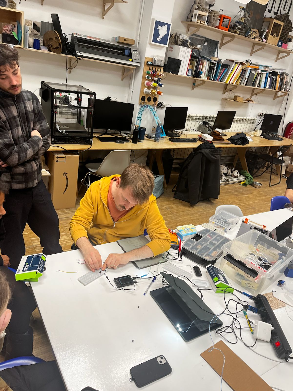
The session began with a hands-on introduction to input devices, focusing on how physical interaction is translated into electrical signals.
Dani demonstrated basic components on a breadboard, with particular attention to the potentiometer as a variable input device.
Key concepts:
- variable resistance as input signal
- voltage division for analog reading
- mapping physical interaction to voltage change
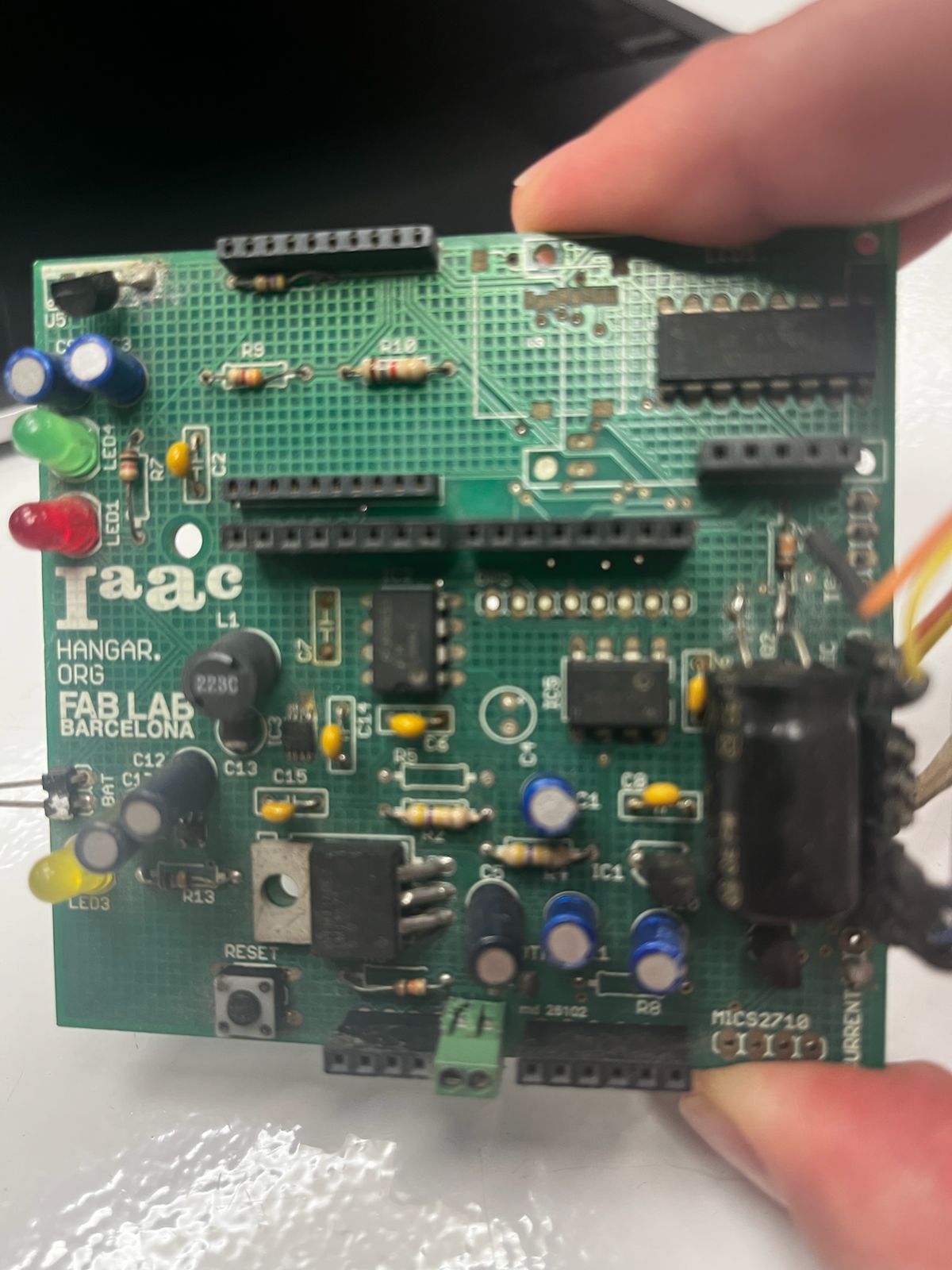
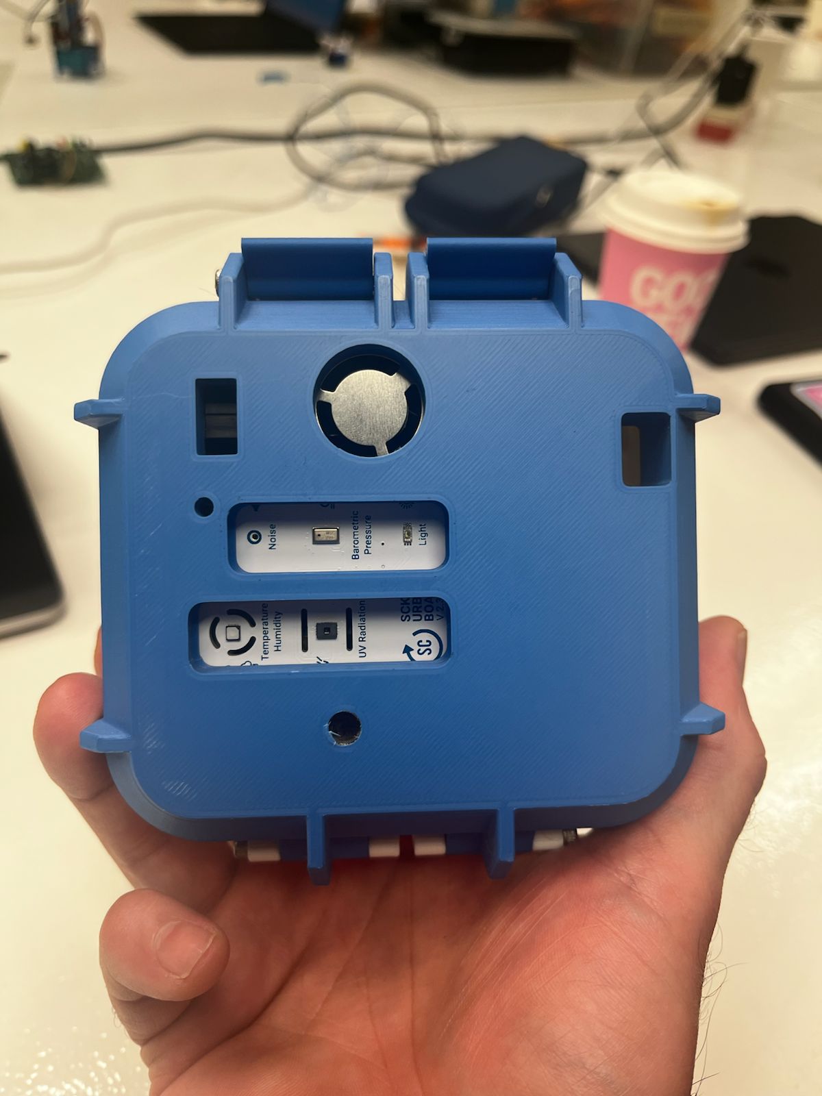
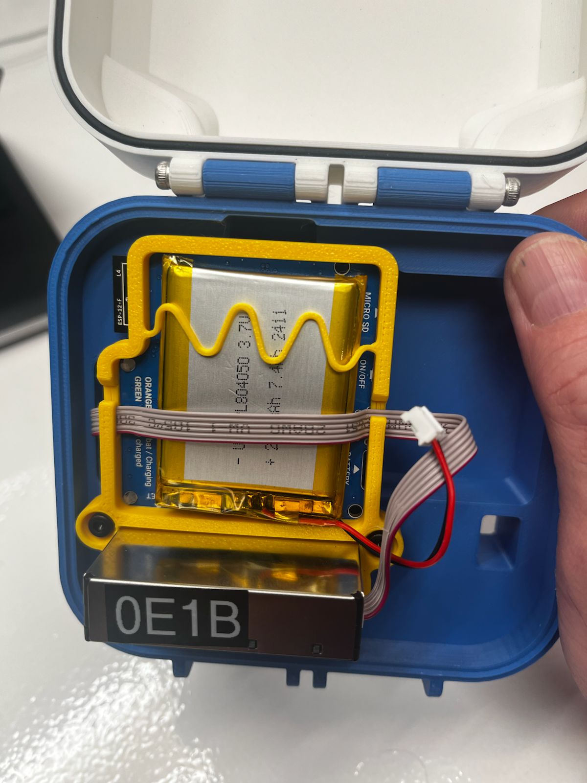
Smart Citizen Project (IAAC)
Adai presented the Smart Citizen project developed at IAAC.
This system integrates multiple environmental sensors into a compact device capable of measuring:
- temperature
- humidity
- air quality
- light
- sound
The project demonstrates how multiple input devices are combined into a coherent sensing system with embedded processing and physical enclosure.
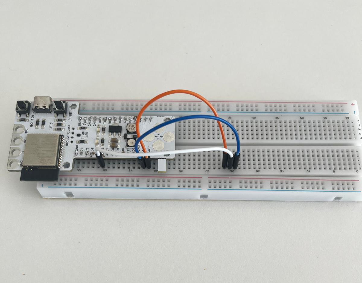
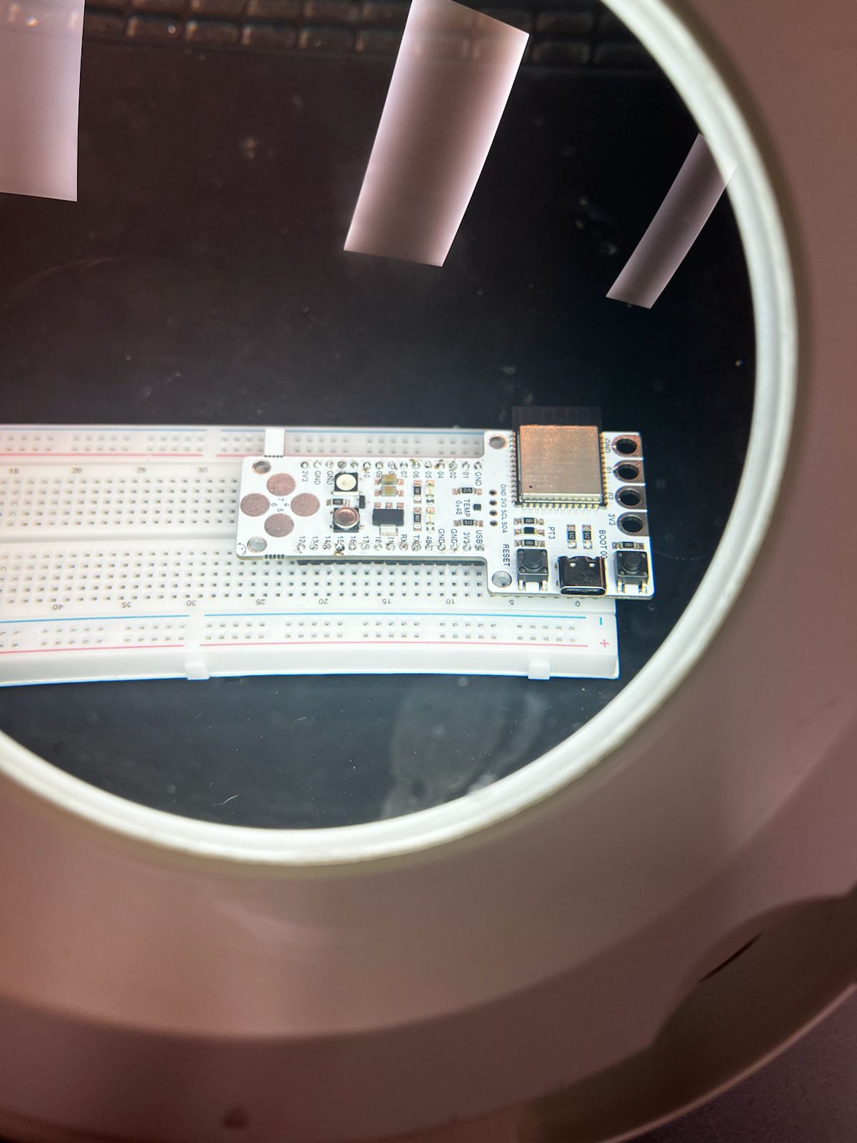
Hands-on — Potentiometer Integration
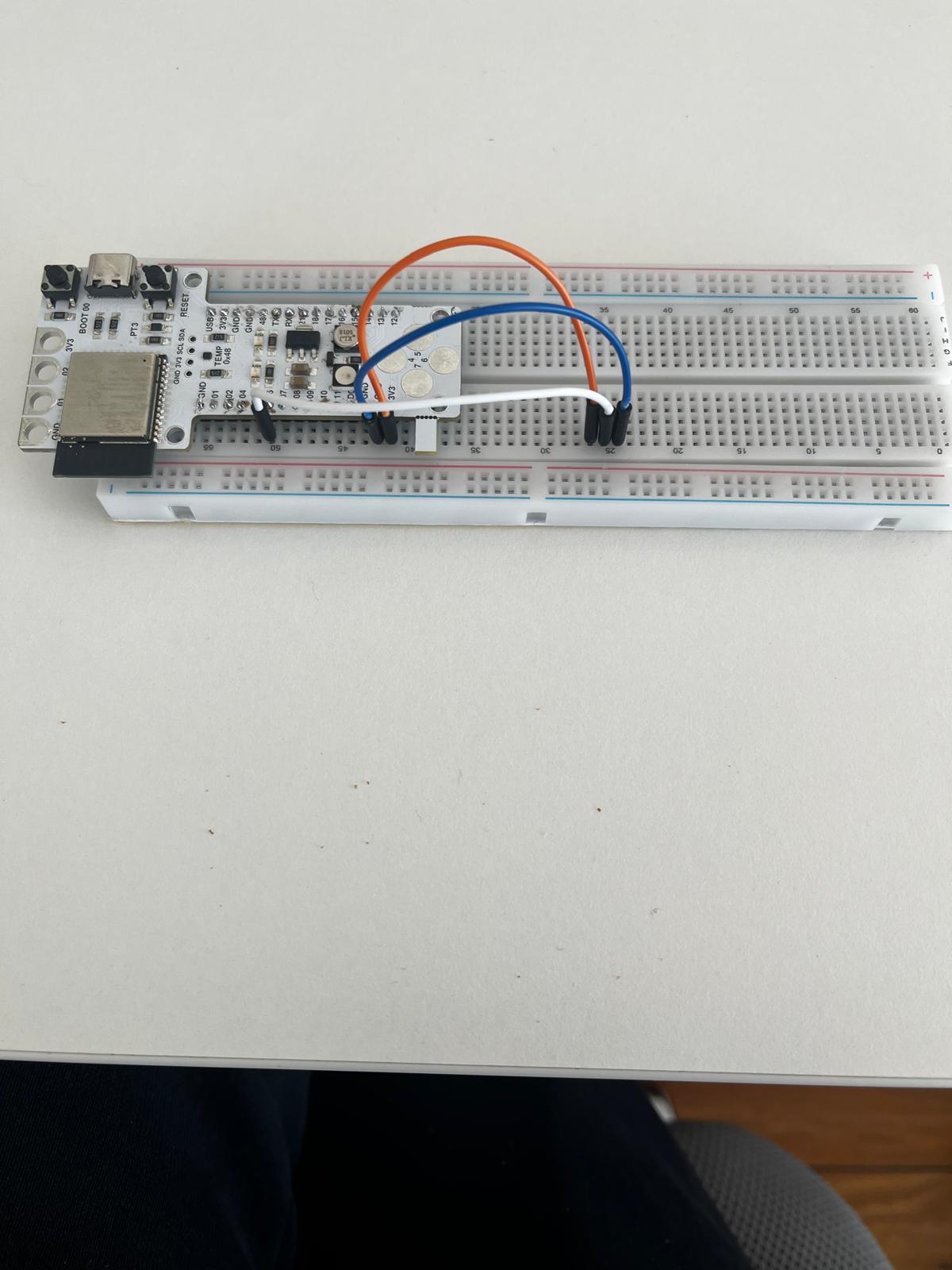
The assembled Barduino board was then placed on a breadboard and connected to a potentiometer to test analog input.
Connections:
- 3.3V → one outer pin of the potentiometer
- GND → opposite outer pin
- wiper (middle pin) → analog input pin on the board
This creates a voltage divider, allowing the output voltage to vary continuously as the potentiometer is turned.
Measurement with Multimeter
A multimeter was used to measure the voltage at the potentiometer output.
Observed behavior:
- approximately 0V at one extreme
- approximately 3.3V at the opposite extreme
- continuous voltage variation between those two values
This confirmed that the potentiometer was functioning correctly as an analog input device.
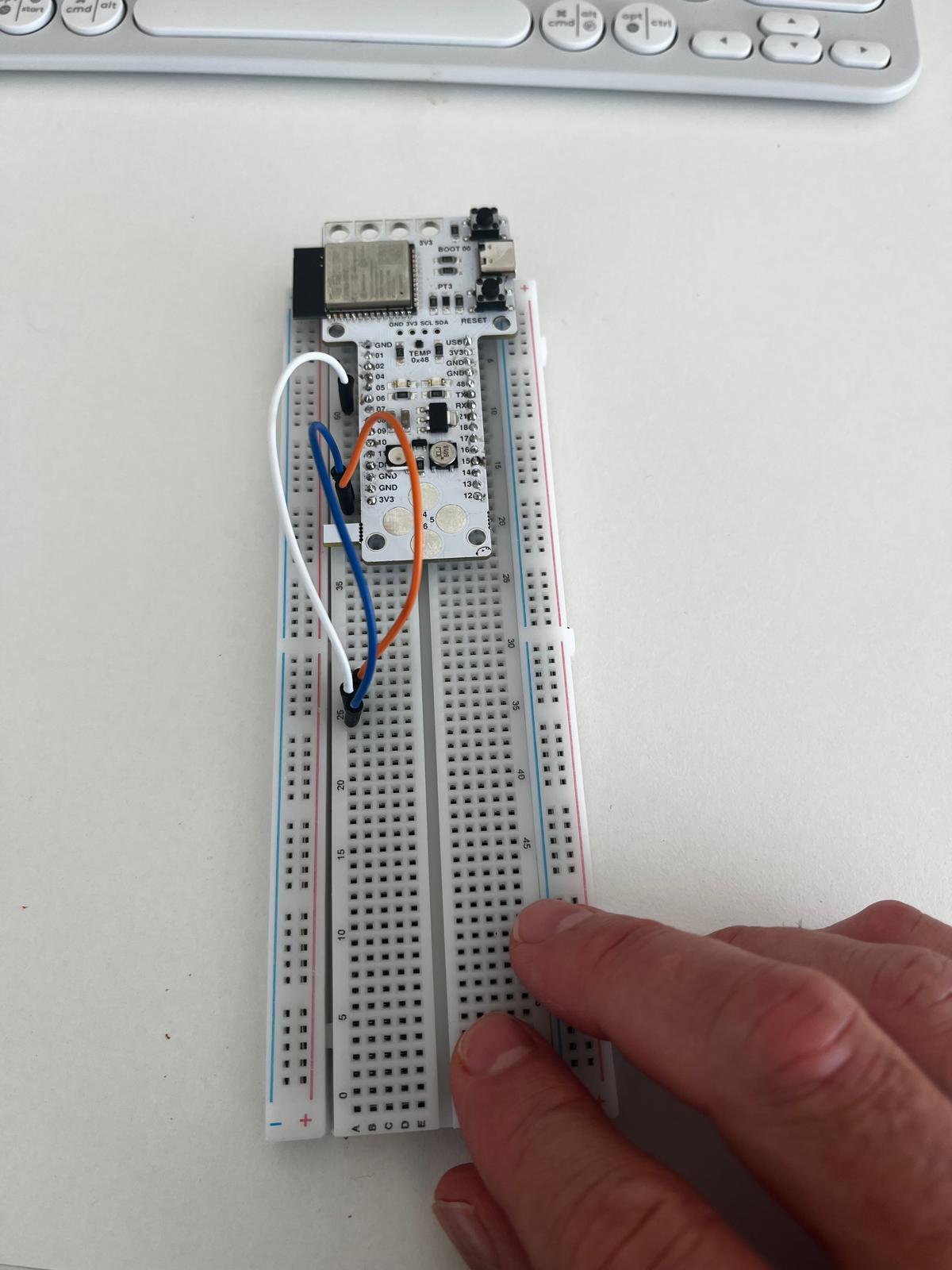
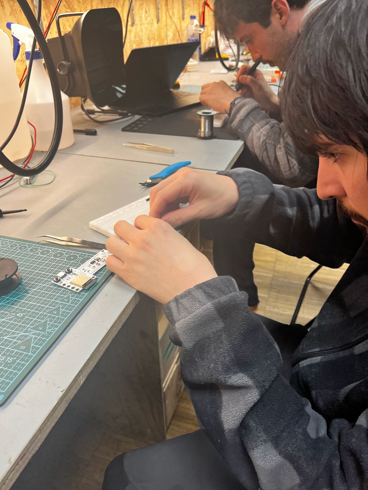
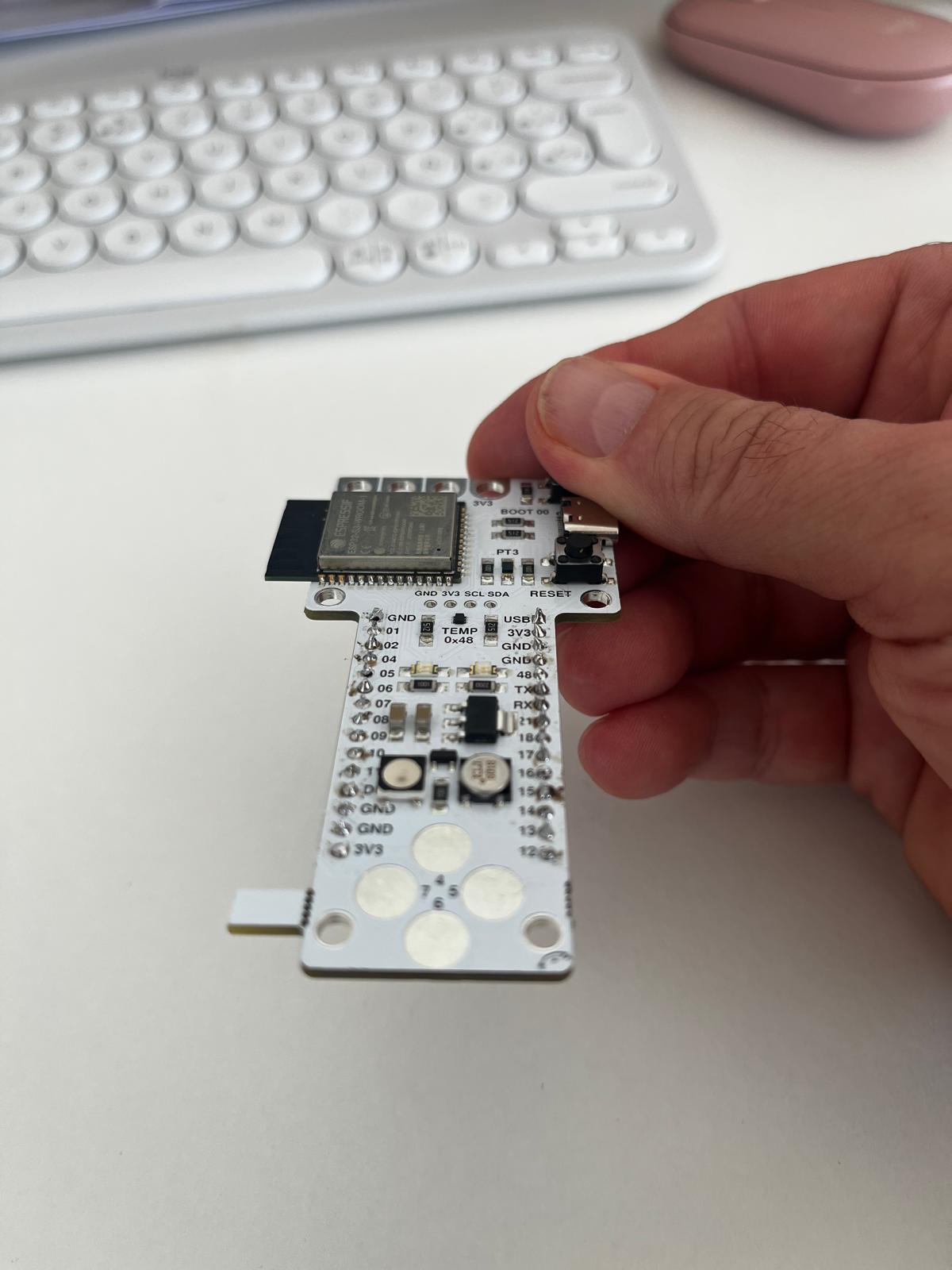
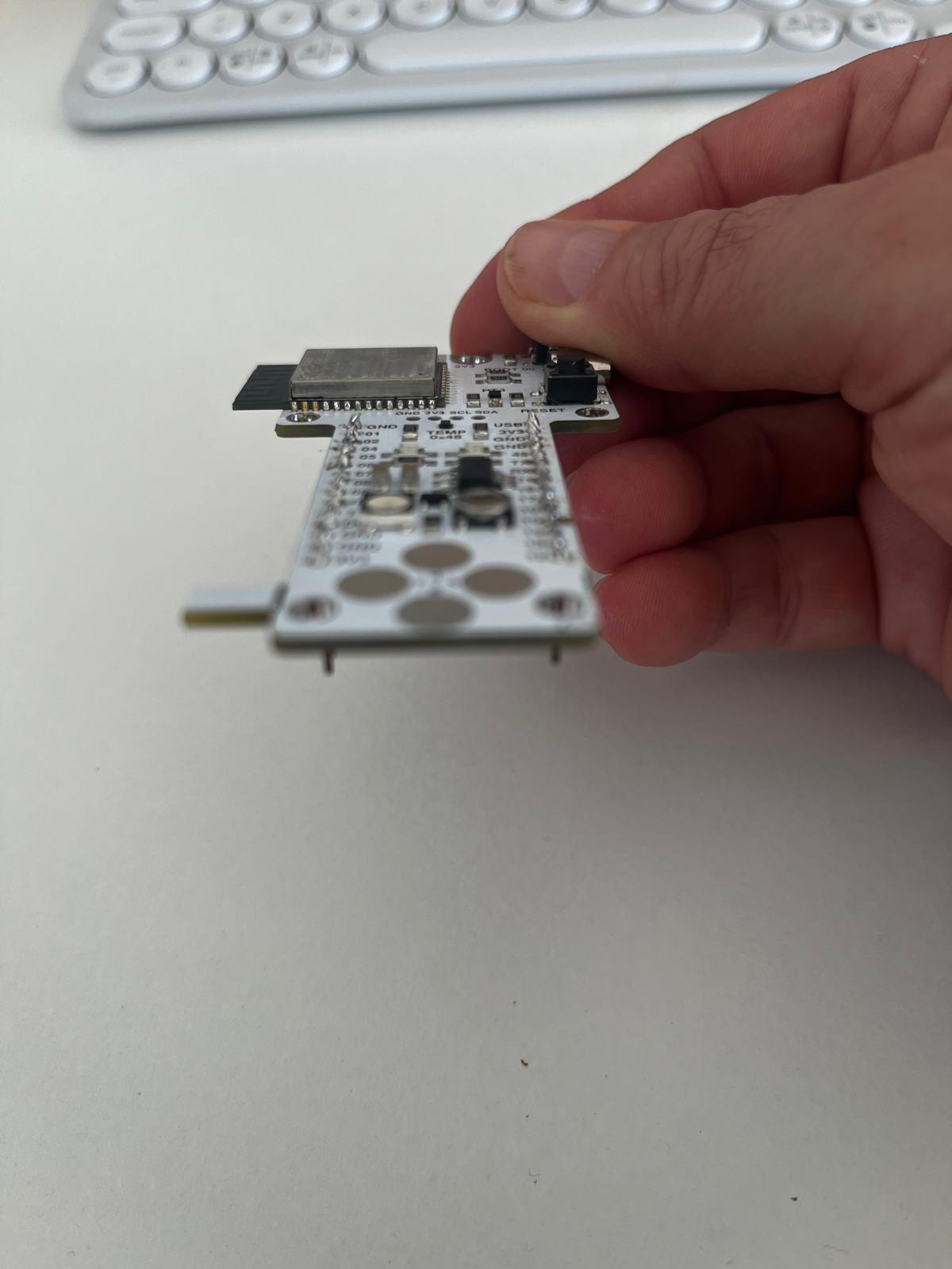
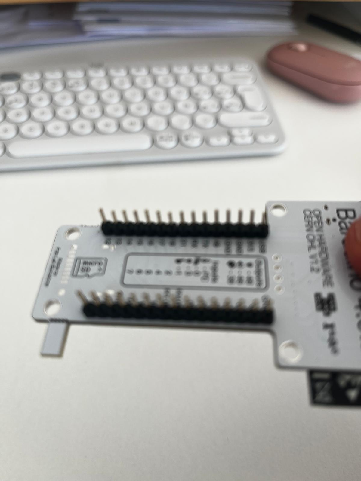
Board Preparation — Barduino Assembly
Before testing input devices, the Barduino development board was prepared by soldering header pins so it could be mounted securely on a breadboard and connected to external components.
Process:
- align pin headers with board holes
- solder each pin carefully
- inspect joints for continuity and avoid solder bridges
This step was important to ensure both mechanical stability and reliable electrical contact during testing.
Observations
- stable voltage variation across the potentiometer range
- direct relationship between rotation and measured voltage
- correct wiring of VCC, GND, and signal is essential
- good soldering quality improves reliability during testing
Key Insight
Input devices convert physical interaction into measurable electrical signals.
In this case, the potentiometer demonstrates clearly how a continuous manual action is translated into a continuous analog voltage that the microcontroller can read and process.
ASFALT Connection
This session directly informs the ASFALT input strategy:
- potentiometer → user control and interface testing
- thermistor → real temperature sensing and thermal feedback
Using the potentiometer as a controllable analog input makes it possible to validate sensing logic before integrating the final temperature sensor.
Group Assignment
Here is the work we did for the group assignment:
Learnings & Reflections
- Input devices convert physical phenomena into electrical signals that can be measured and processed by a microcontroller.
- Analog and digital signals behave differently and require different methods of measurement and interpretation.
- Using tools like multimeters and oscilloscopes helps visualize and validate signal behavior.
- Voltage dividers are fundamental for reading resistive sensors such as potentiometers and thermistors.
- Correct wiring and stable connections are essential to avoid noise and inconsistent readings.
- Reinforced the importance of understanding the full signal path from physical input to digital value.
Weekly Assignment
Thermistor Sensor Test with Custom ASFALT SAMD21 PCB
Assignment Goal
The goal of this assignment was to test and validate the first sensor input workflow on the custom ASFALT SAMD21 PCB.
This exercise focused on:
-
analog sensor acquisition
-
ADC reading on the SAMD21
-
serial communication debugging
-
temporary sensor wiring
-
firmware upload and testing through Arduino IDE
The thermistor module was used as a preliminary environmental input before integrating the final K-type thermocouple system for ASFALT.
Components Used
| Component | Function |
|---|---|
| ASFALT SAMD21 PCB | Main custom microcontroller board |
| ATSAMD21E17A | Main MCU |
| KY-028 Thermistor Module | Temperature sensing module |
| USB cable | Power + programming |
| Male-to-male jumper wires | Temporary wiring |
| Arduino IDE | Firmware upload and debugging |
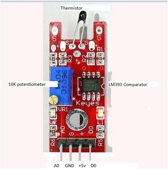
Thermistor Module Analysis
The KY-028 module integrates several useful electronic elements for learning sensor systems.
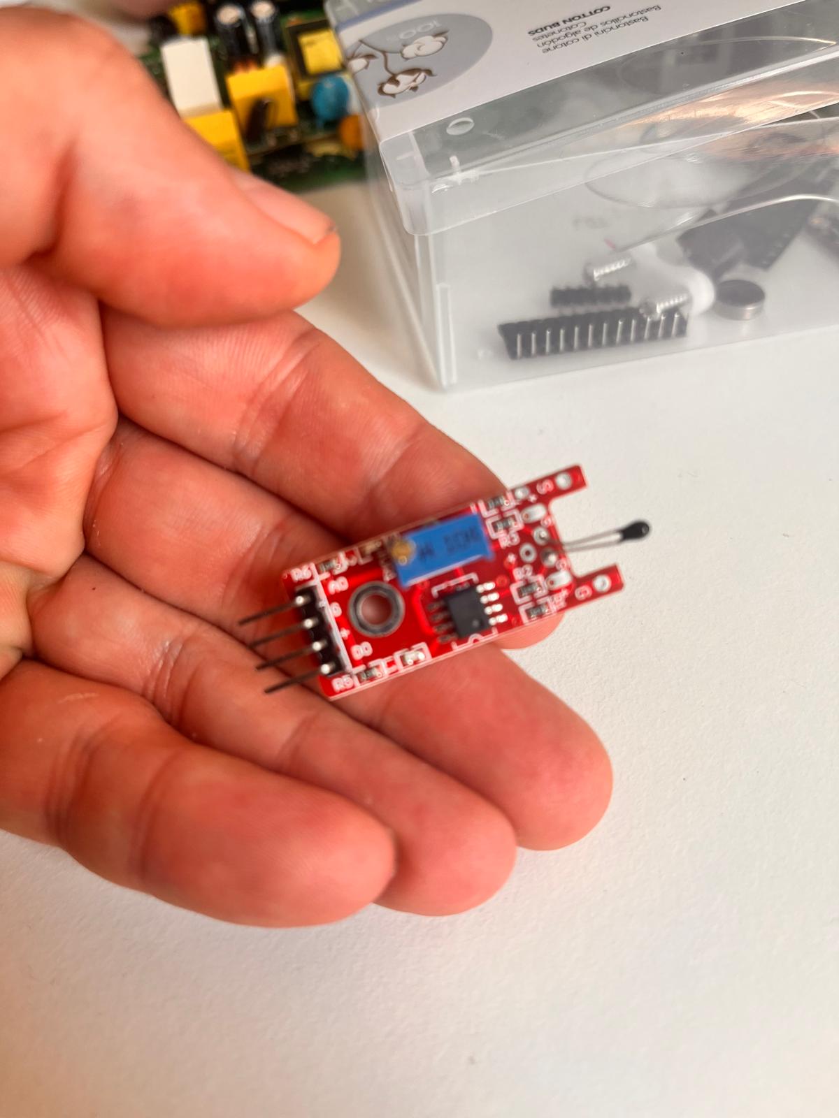
| Part | Function |
|---|---|
| Thermistor bead (black tip) | Temperature-sensitive resistor |
| LM393 Comparator IC | Converts analog signal into digital threshold signal |
| Blue potentiometer | Adjusts digital trigger threshold |
| AO pin | Analog temperature output |
| DO pin | Digital HIGH/LOW threshold output |
| G pin | Ground |
| + pin | Power input |
For ASFALT, only the analog output was used because the final system requires continuous temperature measurement rather than simple threshold switching.
Wiring Setup
The thermistor module was connected directly to the custom ASFALT PCB without using a breadboard.
The connections were:
| Thermistor Module | ASFALT PCB |
|---|---|
| + | VDDIN |
| G | GND |
| AO | ADC_IN_3 |
The DO output was intentionally ignored.
The sensor was powered directly from the SAMD21 board through USB power.
Physical Setup
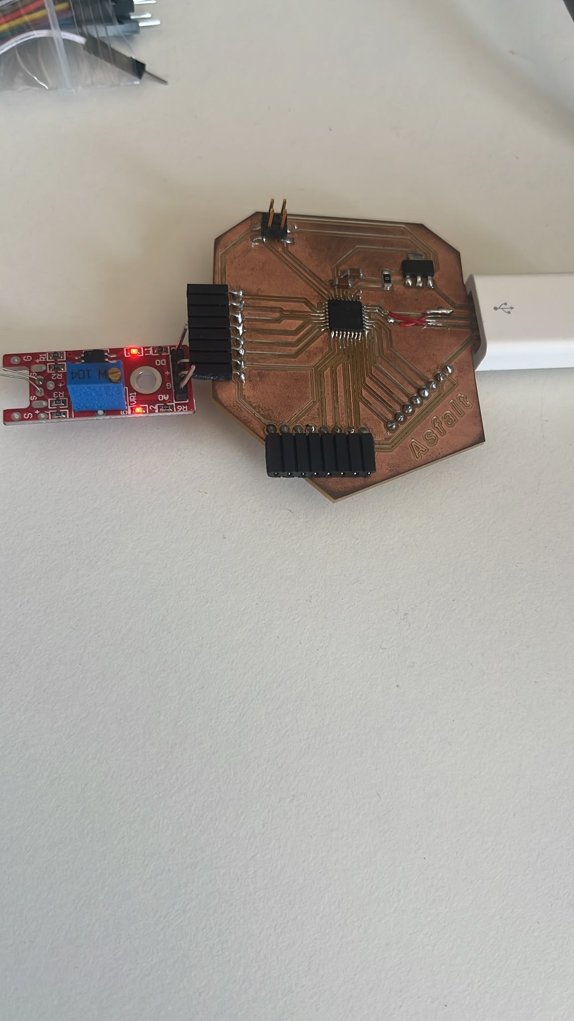
The temporary setup used direct jumper wire contact between the sensor module and the exposed PCB headers.
This allowed rapid testing before final enclosure and wiring integration.
Arduino IDE Setup
The custom SAMD21 PCB was recognized successfully in Arduino IDE using:
-
Board: Generic x21E
-
Baud rate: 115200
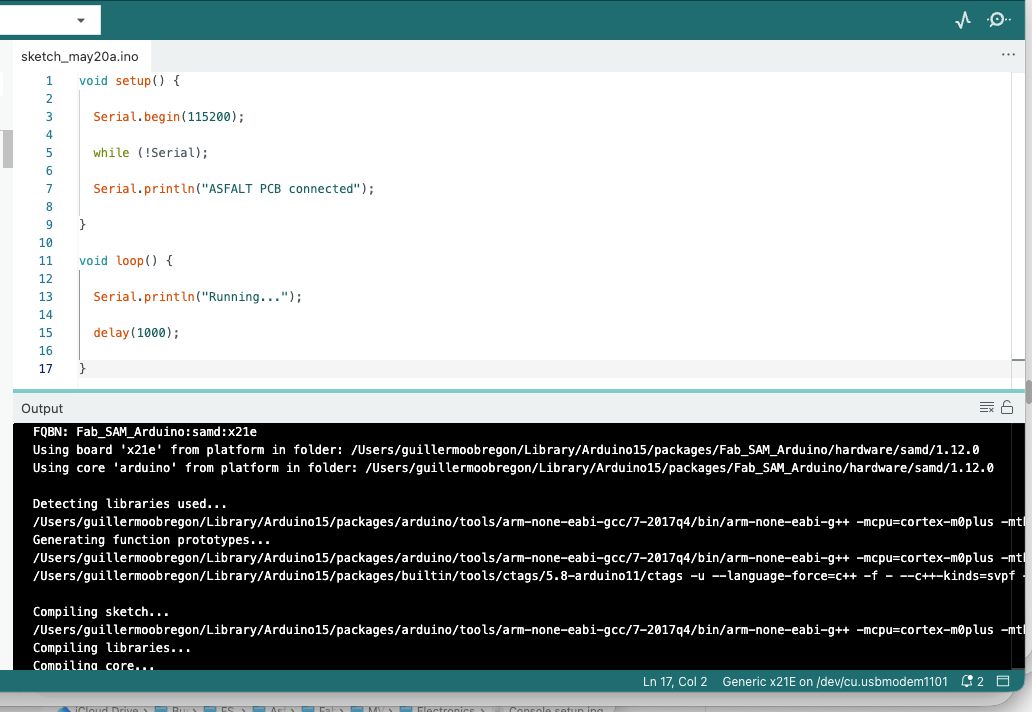
The first uploaded sketch was a simple serial communication test. I used Chatgpt to make sure I had the right command lines.
void setup() {

  Serial.begin(115200);

  while (!Serial);

  Serial.println("ASFALT PCB connected");

}

void loop() {

  Serial.println("Running...");

  delay(1000);

}
Serial Communication Test
After uploading the sketch, the Serial Monitor continuously printed messages.
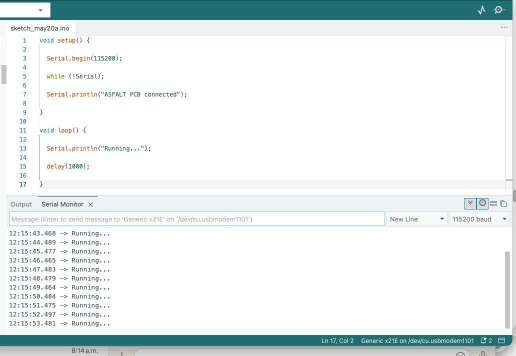
This confirmed that:
-
USB communication worked
-
the SAMD21 bootloader worked
-
the PCB was programmable
-
serial debugging was operational
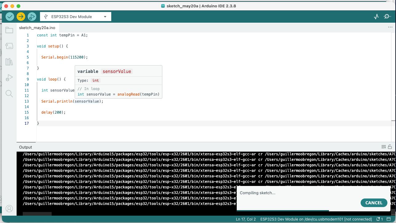
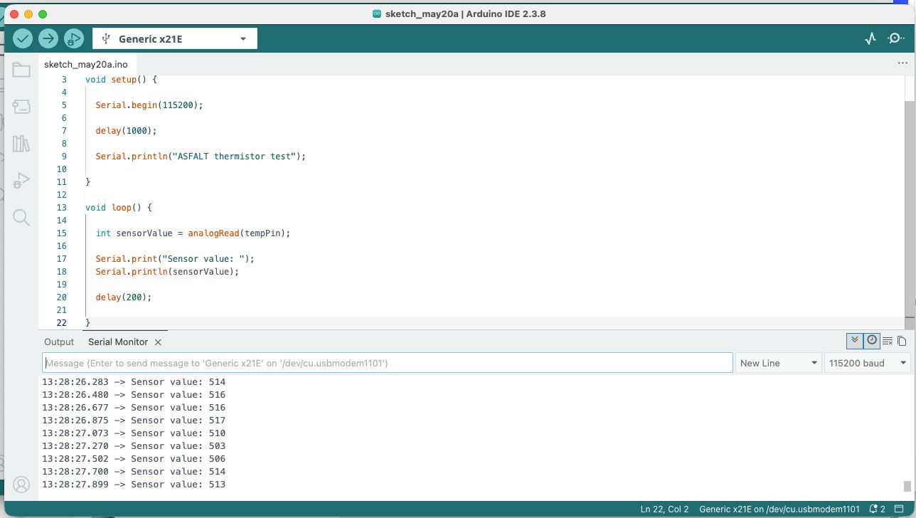
Thermistor Input Code
After confirming the board functionality, I uploaded a second sketch also assisted by Chatpgt to read the thermistor sensor values. I adjusted the pin number with the correct one on the pcb and ran it.
const int tempPin = A3;

void setup() {

  Serial.begin(115200);

  delay(1000);

  Serial.println("ASFALT thermistor test");

}

void loop() {

  int sensorValue = analogRead(tempPin);

  Serial.print("Sensor value: ");

  Serial.println(sensorValue);

  delay(200);

}
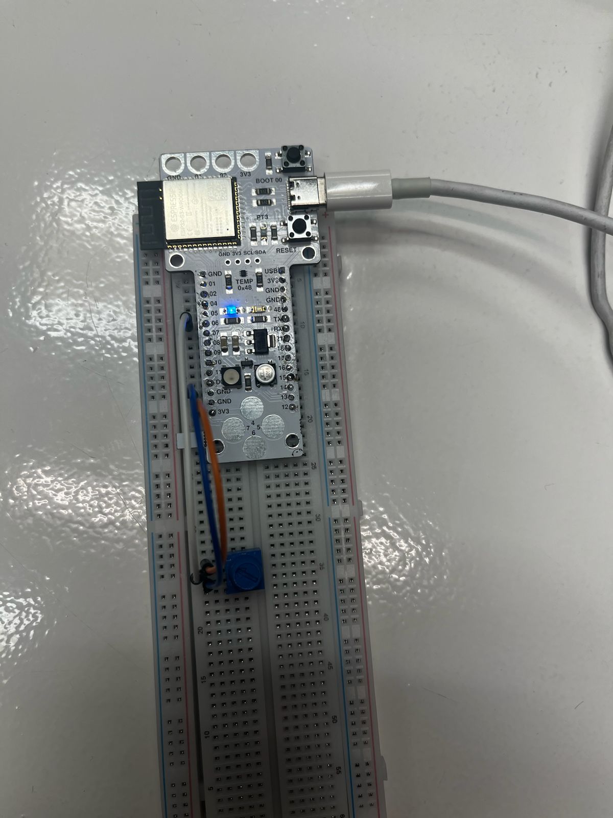
Sensor Readings
The Serial Monitor displayed continuous analog readings from the thermistor.
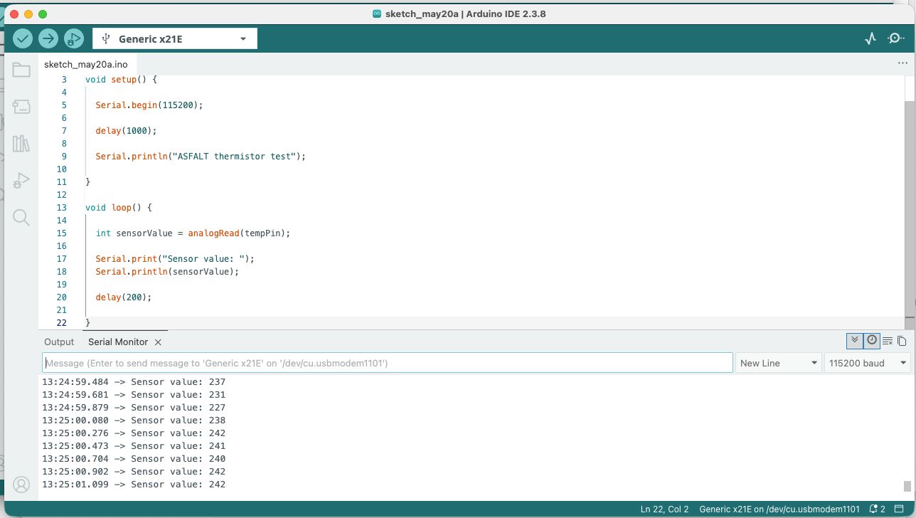
At room temperature, the readings stabilized around:
- 230–240 ADC counts
This confirmed:
-
successful analog acquisition
-
stable ADC behavior
-
correct sensor wiring
-
functioning serial output
Sensor Response Test
To verify that the thermistor reacted to temperature changes, I carefully heated the sensor bead using a lighter at a safe distance.
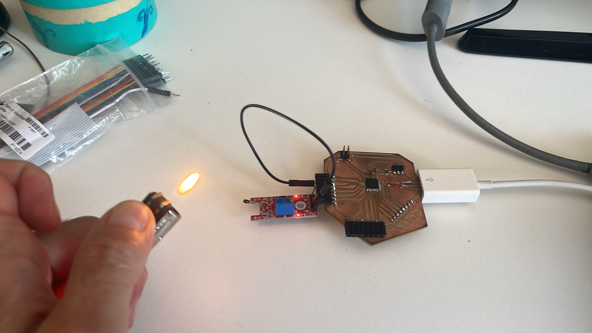
The analog values changed significantly after heating.
The readings increased to approximately:
- 500 ADC counts
This confirmed that the sensor was responding correctly to thermal changes.
Learning Outcomes
This exercise validated the first complete sensor acquisition workflow on the ASFALT platform and verified:
-
custom PCB functionality
-
analog sensor reading
-
ADC operation on SAMD21
-
firmware upload workflow
-
serial debugging workflow
-
environmental sensing capability
It also clarified the future ASFALT architecture:
Sensor
↓
Signal acquisition
↓
MCU processing
↓
Serial debugging
↓
Future heater control
Relevance to ASFALT
Although the final ASFALT system will use:
-
K-type thermocouples
-
MAX31856 thermocouple amplifiers
The overall software and embedded architecture remains very similar:
-
temperature monitoring
-
closed-loop heating control
-
SSR switching logic
-
PID implementation
This marked the transition from PCB fabrication into fully functional embedded system development.
Reflection
This assignment was an important milestone because it demonstrated that the custom ASFALT PCB is fully programmable and capable of reading real-world environmental data.
The exercise also highlighted the importance of rapid temporary prototyping before integrating the final industrial components.
Using a simple thermistor module allowed me to validate the entire embedded workflow safely before working with high-temperature heaters and mains power systems.
References
Documentation
-
Arduino IDE documentation
https://docs.arduino.cc/software/ide-v2 -
Microchip ATSAMD21 Datasheet
https://ww1.microchip.com/downloads/en/DeviceDoc/SAM_D21_DA1_Family_DataSheet_DS40001882F.pdf -
KY-028 Thermistor Module documentation
https://arduinomodules.info/ky-028-digital-temperature-sensor-module/
AI Assistance
Again, the custom GPT was used during this assignment for:
- debugging the SAMD21 PCB setup
- understanding analog sensor workflows
- explaining thermistor module functionality
- generating Arduino code structure
- reviewing wiring logic
- organizing technical documentation
- improving markdown formatting for Zed and Fab Academy documentation
AI was used as a collaborative engineering assistant rather than as a replacement for physical experimentation or testing.
Example Prompts Used
- “How to connect KY-028 thermistor module to SAMD21 custom PCB”
- “Explain analog input workflow for thermistor sensor”
- “Write Arduino code to read thermistor values from ADC pin”
- “How to debug SAMD21 USB connection in Arduino IDE”
- “Document Input Devices week for Fab Academy in markdown format”
- “Explain thermistor module components and pinout”
- “How to structure embedded system architecture for ASFALT”