Week 10 — Output Devices
Global Class
This week focuses on how microcontrollers interact with the physical world by driving external devices. Outputs convert digital signals into physical actions such as light, motion, sound, or heat.
Types of Output Devices
Common output categories include:
- LEDs and displays
- speakers and audio systems
- motors and actuators
Power and Energy Considerations
Unlike input devices, outputs often require significant power.
Key concepts:
- voltage
- current
- power consumption
Incorrect design can lead to:
- overheating
- component damage
- unstable system behavior
Electrical Safety
Working with output devices introduces higher power levels.
Important thresholds:
- ~1 mA → generally safe
- ~10 mA → muscle contraction
- ~100 mA → dangerous (fibrillation risk)
Additional risks:
- stored energy in capacitors
- inductive voltage spikes (flyback)
Safe practices:
- clear wiring
- controlled testing environment
- avoid working alone
- verify circuits before powering
Power Supply Strategies
Different approaches to powering systems:
- bench power supplies (controlled testing)
- USB power delivery (flexible and accessible)
- battery systems (LiPo)
- DC-DC converters
Modern USB-C systems allow dynamic voltage and current negotiation.
Power Measurement
Understanding consumption is essential:
- measure voltage and current
- calculate power usage
- ensure components operate within limits
Tools:
- multimeter
- inline current measurement
Output Control
Microcontrollers typically cannot drive high-power devices directly.
Instead, they use:
- transistors
- drivers
- relays or solid-state relays (SSR)
This creates a safe interface between low-voltage control and high-power systems.
Local Class
Output Devices Introduction
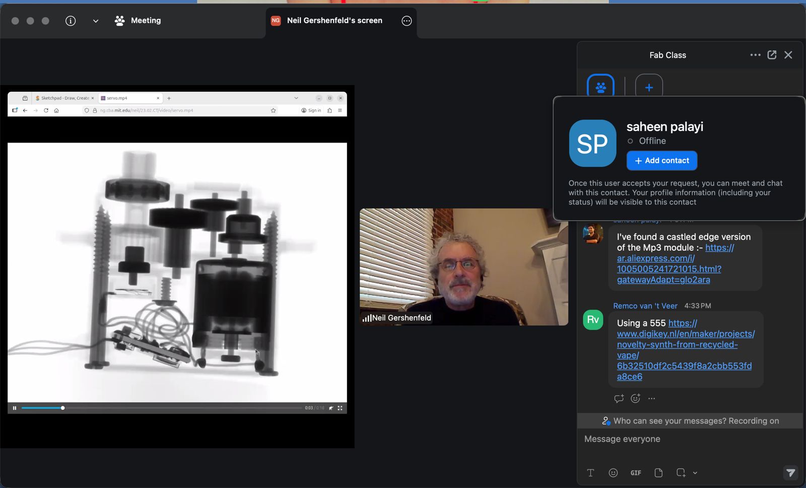
This session focused on how microcontrollers drive physical systems through output devices. The main idea is that outputs translate digital signals into real-world effects such as light, motion, and heat.
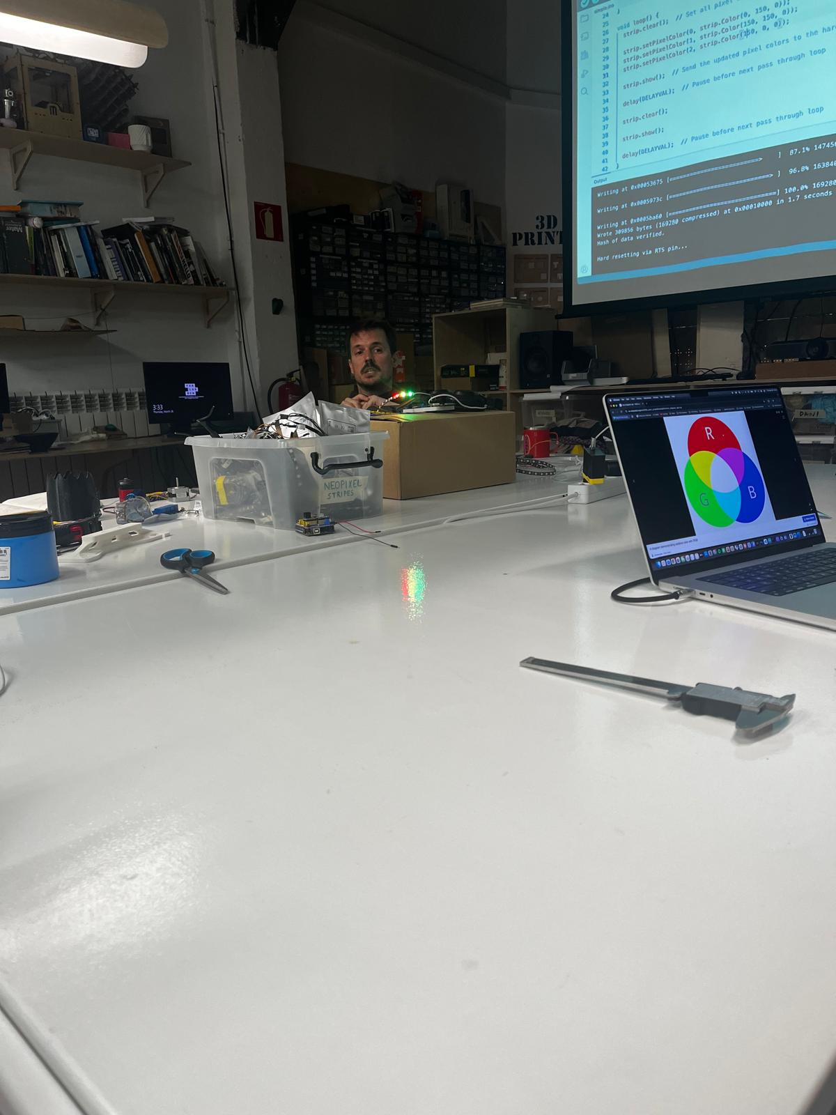
Dani demonstrated LED control using programmable lighting, showing how digital signals can generate dynamic visual behavior.
Light — Addressable LEDs
We explored NeoPixel (addressable LED) systems.
Key concepts:
- each LED has an individual address
- controlled through a single data line
- requires specific timing and libraries (Adafruit / Arduino IDE)
This introduces the idea of complex outputs controlled through simple interfaces.
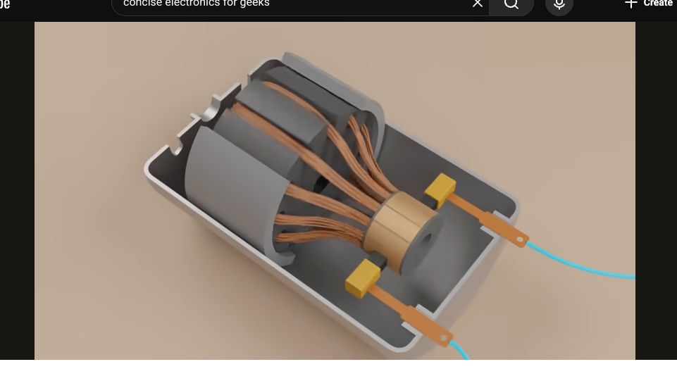
Motors and Motion
Different motor types were introduced, focusing on their behavior and control:
- DC motors → simple, continuous rotation
- stepper motors → precise position control, lower torque
- BLDC motors → efficient, high-performance systems
- servo motors → controlled angular position using PWM signal (typically limited range)
Key parameters:
- torque
- speed
- control method
A visual explanation of motor structure helped understand internal operation.
Switching High Power
To control real-world devices, microcontrollers require switching components:
- MOSFET → fast electronic switch (transistor-based)
- relay / SSR → electrically isolated switching
Microcontrollers do not drive power directly — they control switching devices.
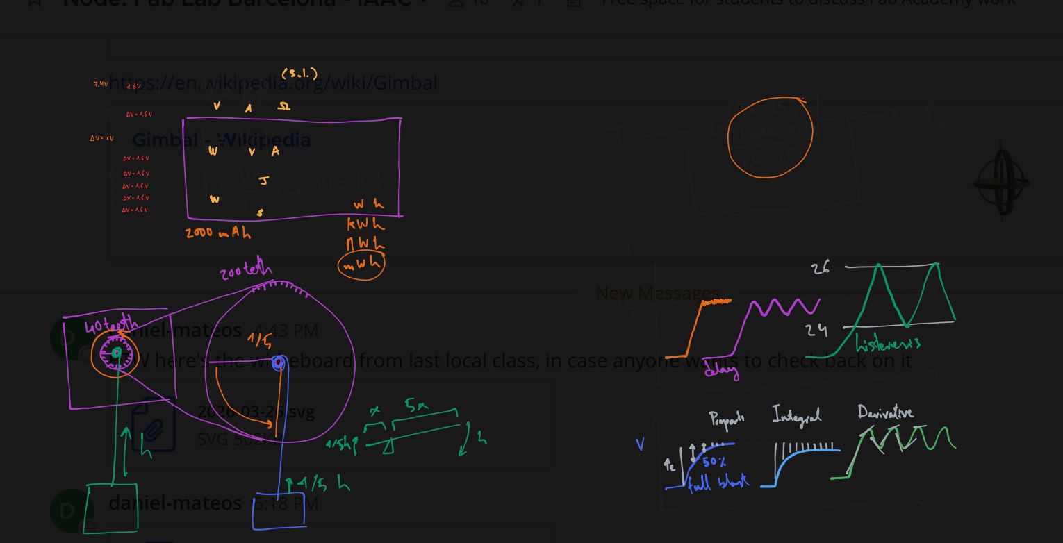
Control Logic — PID
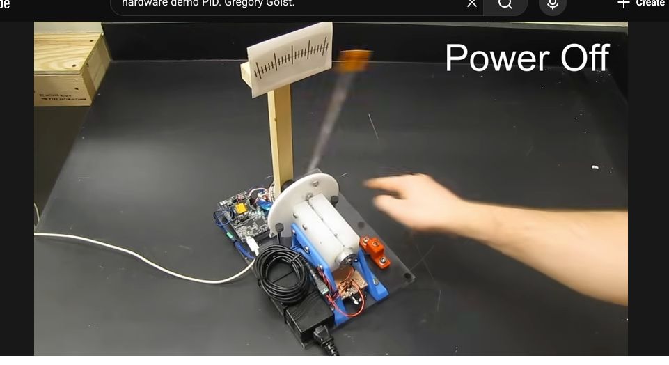
A hardware demonstration of a PID controller showed how systems can regulate behavior dynamically.
Concepts introduced:
- proportional → reacts to current error
- integral → accumulates past error
- derivative → predicts future behavior
This allows systems to stabilize outputs such as:
- motor position
- temperature
- speed
Relevance to ASFALT
This session directly defines the ASFALT actuation system:
- SSR / MOSFET → control heating element
- LEDs → system feedback and status
- PID → future temperature regulation
Together, these elements define how ASFALT:
- delivers heat
- controls energy
- responds to sensor input
Group Assignment
Here is the work we did for the group assignment:
Learnings & Reflections
- Output devices translate digital signals into physical actions such as light, motion, or heat.
- Microcontrollers cannot directly drive high-power devices and require switching components such as MOSFETs or relays.
- Power, voltage, and current must be considered carefully to avoid damaging components or creating unsafe conditions.
- PWM is an effective method for controlling output intensity and simulating variable power delivery.
- Understanding switching architecture is key to bridging low-power control and real-world actuation.
- Reinforced the importance of safe testing practices when working with higher power systems.
Individual Assignment
Relay and SSR Output Control with Custom ASFALT SAMD21 PCB
Assignment Goal
The goal of this assignment was to validate digital output control using the custom ASFALT SAMD21 PCB, that represents the ASFALT heating system, without using high-voltage components.
This exercise focused on:
- digital output configuration
- GPIO control
- relay switching
- SSR triggering
- actuator interfacing
- embedded control architecture
The assignment represents the first complete actuator control workflow for ASFALT.
Components Used
| Component | Function |
|---|---|
| ASFALT SAMD21 PCB | Main custom microcontroller board |
| ATSAMD21E17A | Main MCU |
| Single-channel relay module | Mechanical switching output |
| Two-channel SSR module | Solid state switching output |
| USB cable | Power + programming |
| Male-to-male jumper wires | Temporary wiring |
| Arduino IDE | Firmware upload and debugging |
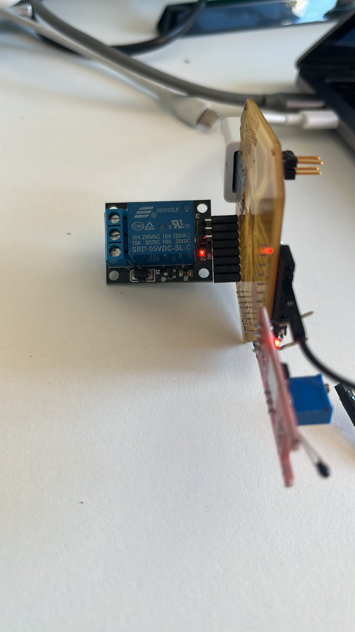
Mechanical Relay Module Analysis
The first test used a standard 5V mechanical relay module.
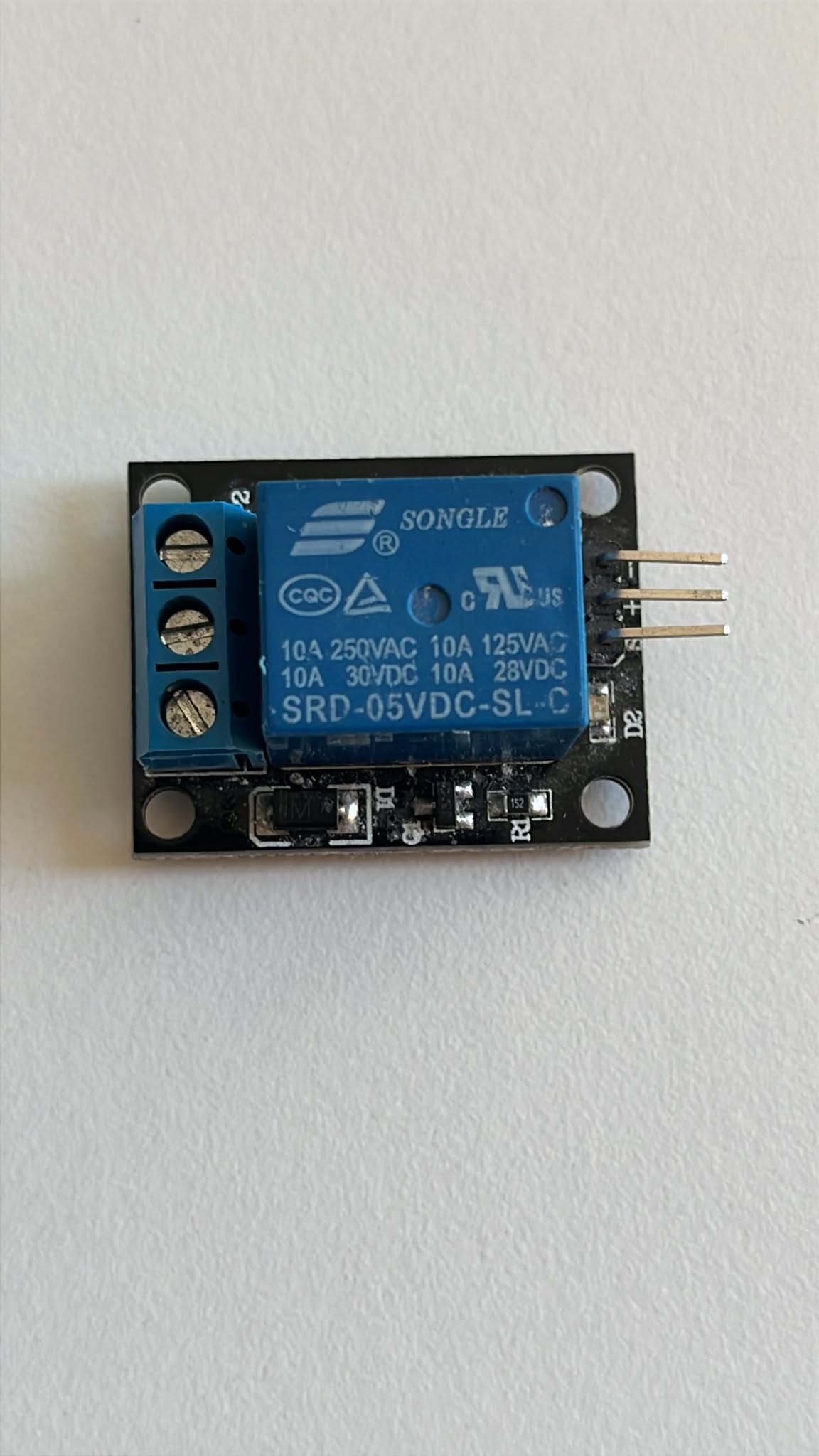
The relay uses an electromagnetic coil to mechanically switch contacts.
| Part | Function |
|---|---|
| Relay coil | Activates internal switching mechanism |
| COM terminal | Common output terminal |
| NO terminal | Normally open contact |
| NC terminal | Normally closed contact |
| IN pin | Digital trigger input |
| VCC pin | Power input |
| GND pin | Ground |
Mechanical relays produce an audible clicking sound during switching.
This makes them useful for debugging and understanding digital outputs.
Relay Wiring Setup
The relay module was connected directly to the custom ASFALT PCB through the J5 header.
The relay input signal was connected to:
- MCU digital pin PA19
This allowed direct relay control without external breadboards.
Relay Physical Setup
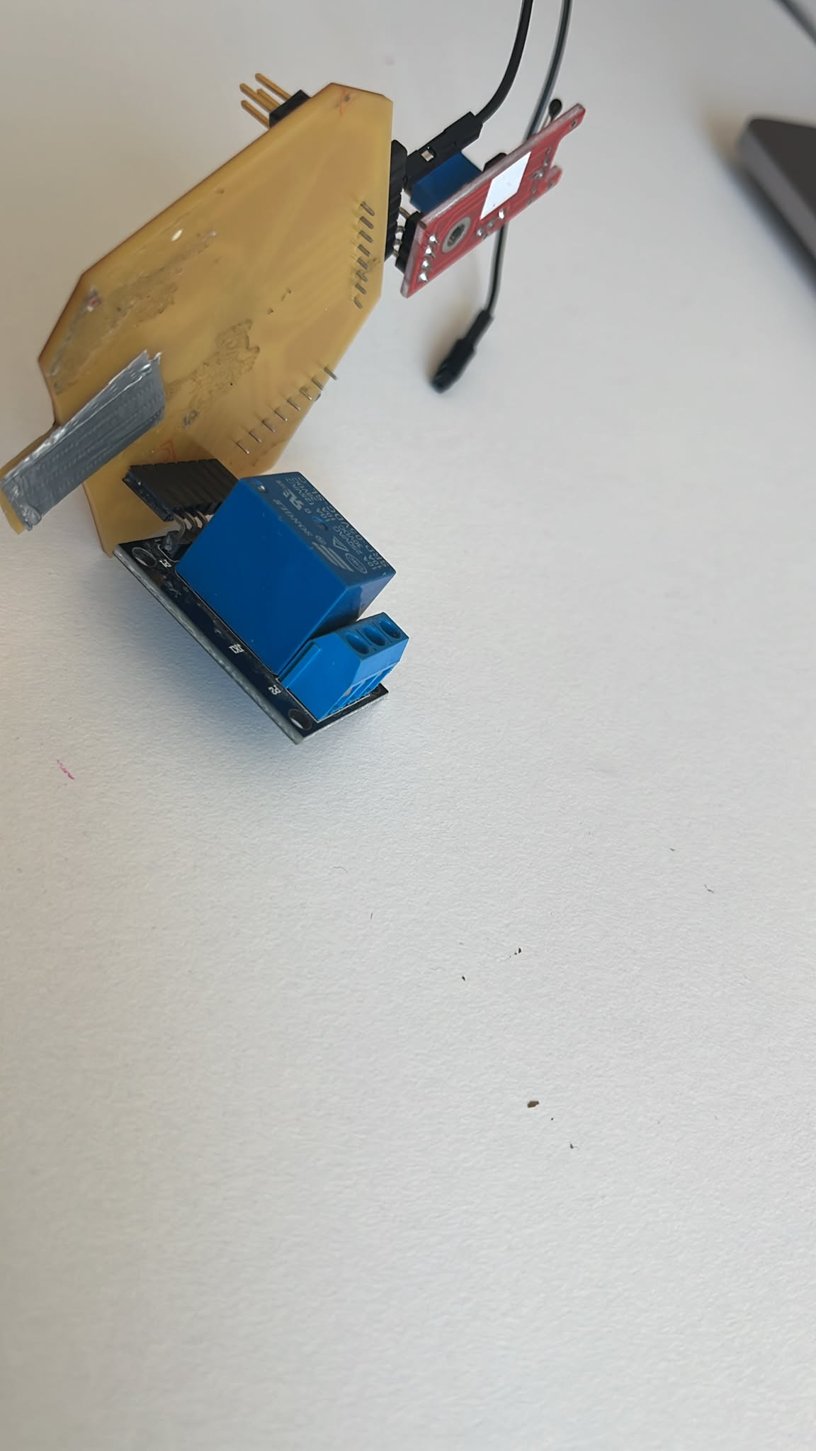
The relay module was mounted directly onto the PCB header pins to simplify the temporary setup.
This rapid prototyping approach reduced wiring complexity during testing.
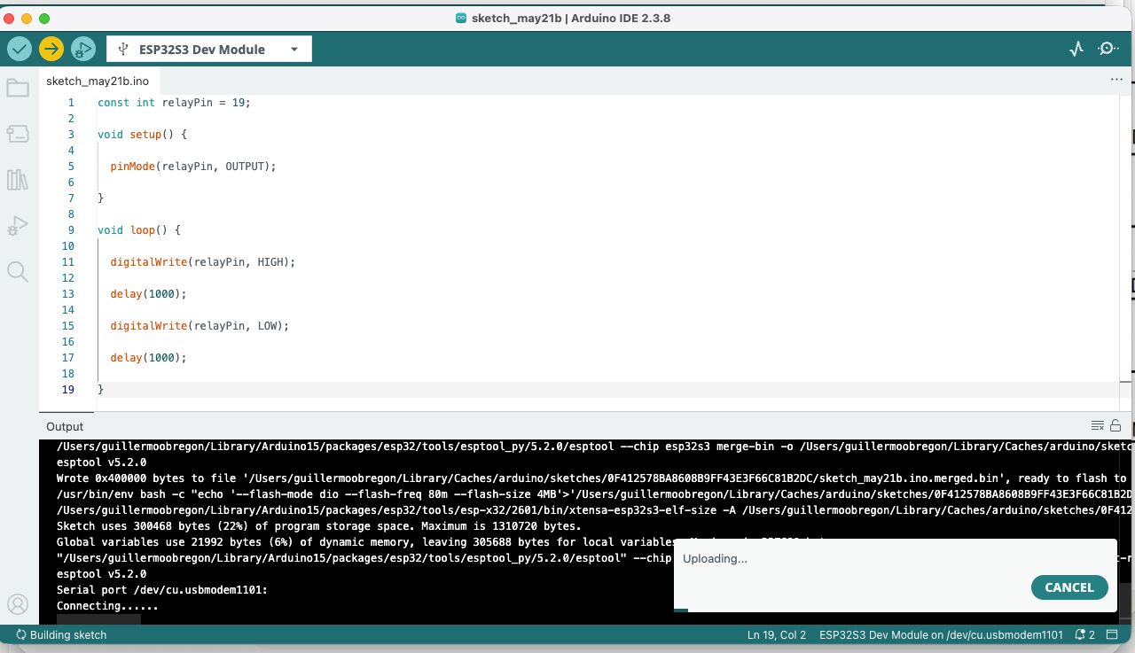
Relay Firmware
The following Arduino sketch was used to toggle the relay ON and OFF every second. I used Chatpgt to wrie the basic code and then I changed the pin number to correct ones verifying it with physical pcb pins.
const int relayPin = 19;

void setup() {

  pinMode(relayPin, OUTPUT);

}

void loop() {

  digitalWrite(relayPin, HIGH);

  delay(1000);

  digitalWrite(relayPin, LOW);

  delay(1000);

}
Relay Test Results
After uploading the sketch:
- the relay clicked every second
- the onboard LED blinked
- the relay toggled correctly
This confirmed:
- successful GPIO output control
- stable digital switching
- correct PCB routing
- successful actuator interfacing
Relay Operation
The relay switching behavior was validated physically during operation.
The test confirmed that the custom ASFALT PCB could safely control external output hardware.
Solid State Relay (SSR) Analysis
After validating the mechanical relay, a two-channel SSR module was tested.
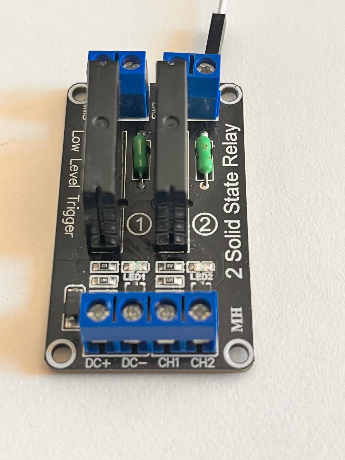
Unlike mechanical relays, SSRs contain no moving parts.
Advantages of SSRs:
- silent operation
- faster switching
- longer lifespan
- better for rapid heater cycling
- ideal for PID thermal control
This makes SSRs more appropriate for the final ASFALT thermal system.
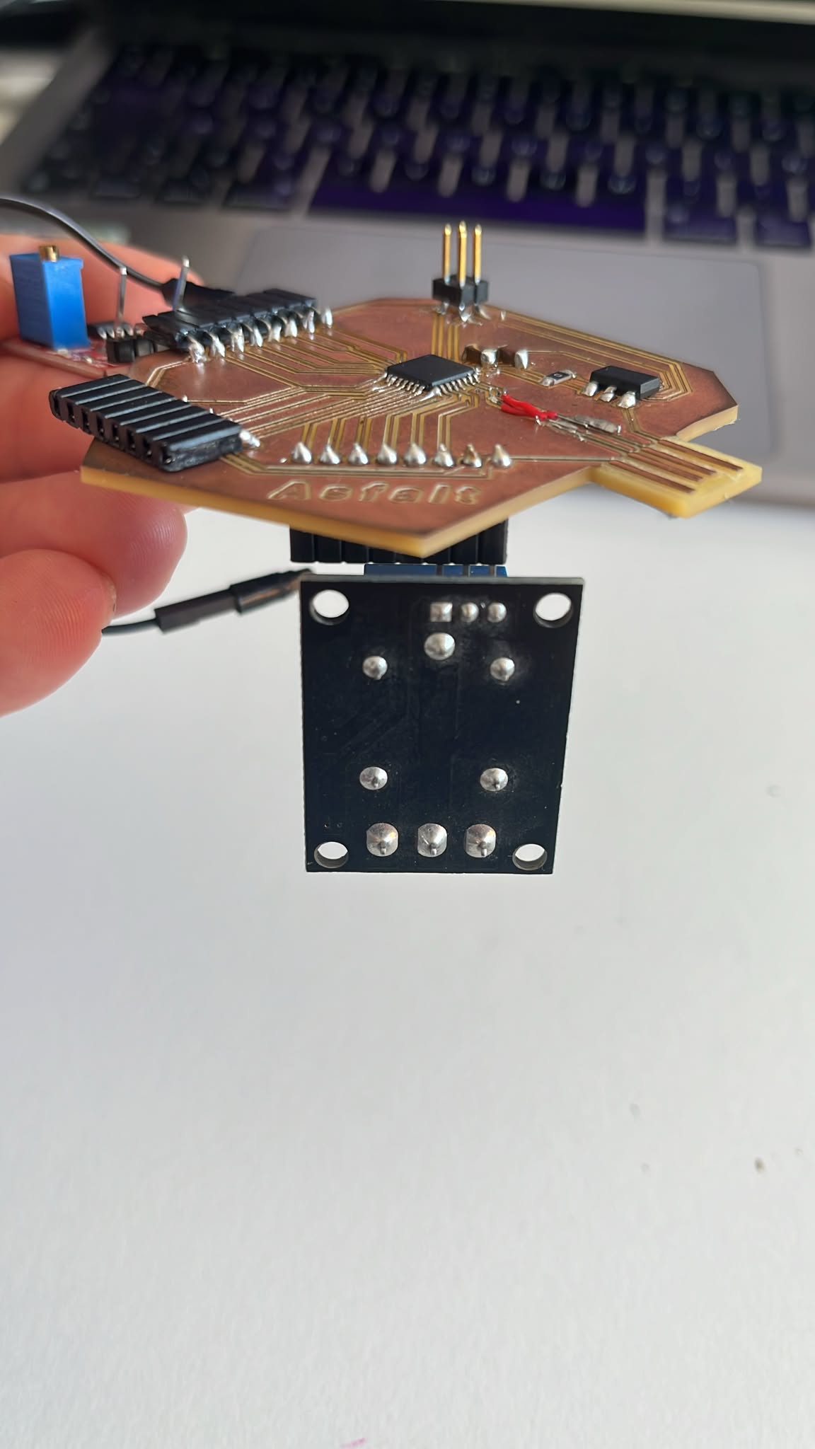
SSR Wiring
The SSR module was connected using jumper wires.
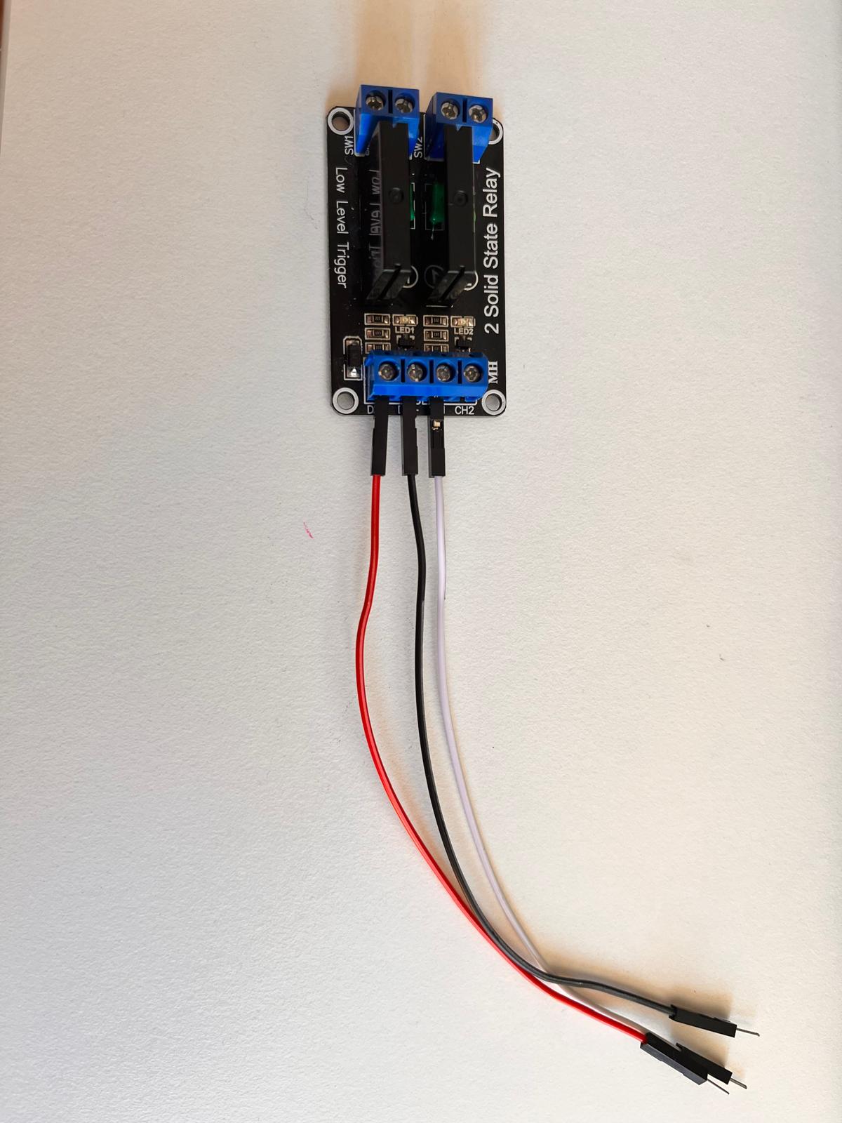
Connections used:
| SSR Module | ASFALT PCB |
|---|---|
| DC+ | VDDIN |
| DC- | GND |
| CH1 | PA19 digital output |
The SSR module used a low-level trigger configuration.
SSR Connection to ASFALT PCB
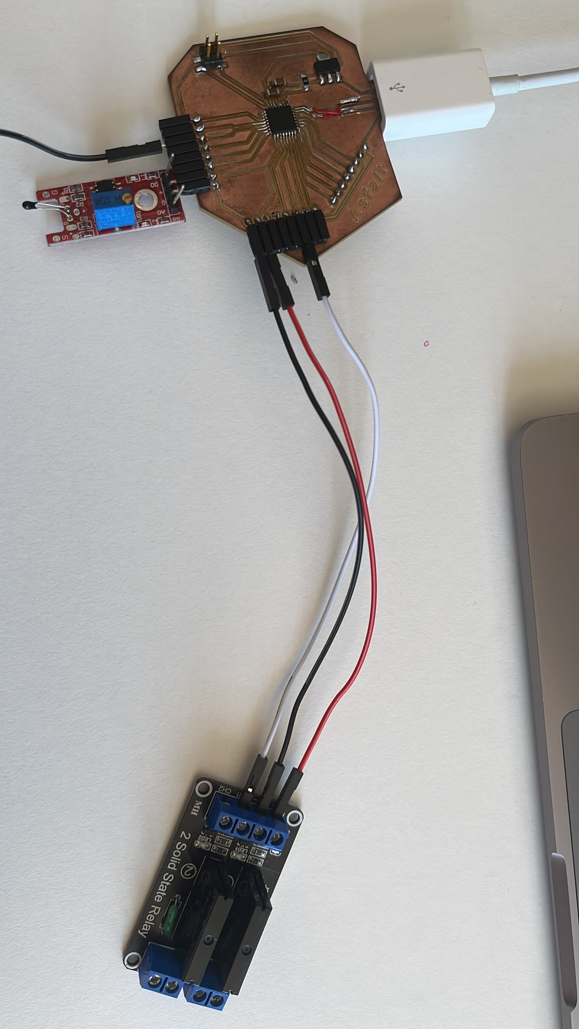
The SSR module was powered directly from the custom PCB.
The output control line was connected to the same digital output pin used previously for the relay test.
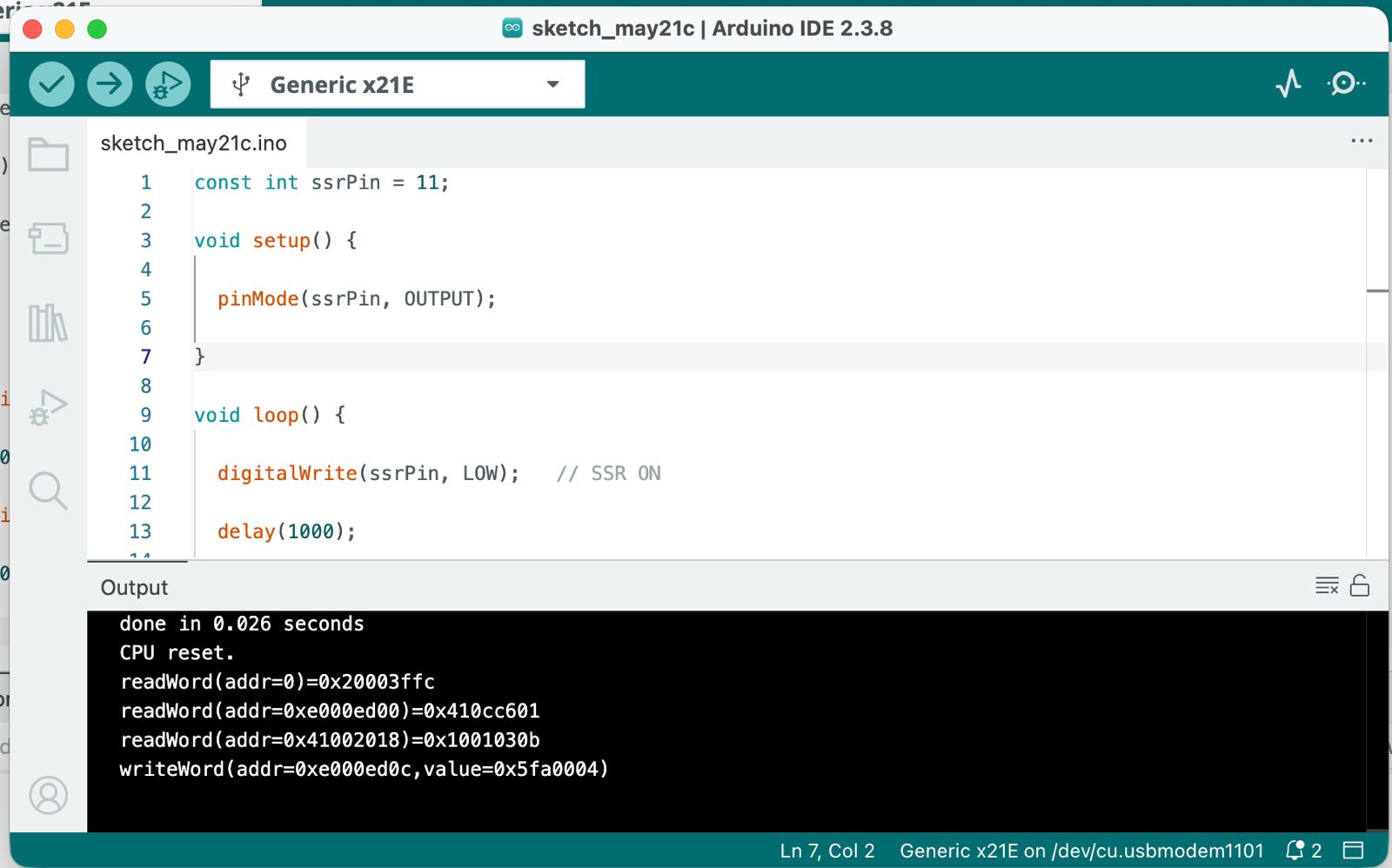
SSR Firmware
The SSR required inverted logic because the module uses low-level triggering. Chatgpt assited on confirming code and I changed pin numbers and connections according to easiest access on physical pcb.
const int ssrPin = 11;

void setup() {

  pinMode(ssrPin, OUTPUT);

}

void loop() {

  digitalWrite(ssrPin, LOW);   // SSR ON

  delay(1000);

  digitalWrite(ssrPin, HIGH);  // SSR OFF

  delay(1000);

}
SSR Test Results
During testing:
- the onboard SSR LED blinked
- the module switched correctly
- the ASFALT PCB controlled the SSR successfully
The SSR operated silently because no mechanical contacts are present.
This validated the first solid-state switching architecture for ASFALT.
ASFALT Integration
This assignment represents a major milestone for the ASFALT project.
The custom PCB can now:
- read analog sensor inputs
- process embedded logic
- control external switching hardware
- drive thermal control systems
Reflection
This assignment significantly improved understanding of:
- digital outputs
- GPIO behavior
- actuator interfacing
- relay switching systems
- SSR operation
- embedded control workflows
The relay module was useful for learning and debugging because the switching could be heard physically.
The SSR module was more relevant for ASFALT because thermal systems require frequent and reliable switching without mechanical wear.
This week established the first complete control loop architecture for ASFALT.
References
- Arduino IDE documentation
- ATSAMD21 datasheet
- Single relay module documentation
- SSR module documentation
AI Assistance
AI tools were used to support:
- debugging Arduino firmware
- interpreting sensor behavior
- documenting workflow
- structuring weekly assignments
- improving technical writing clarity
Example prompts used:
- “Help debug SAMD21 analogRead behavior”
- “Generate Arduino relay blinking test code”
- “Explain low-level trigger SSR behavior”
- “Help structure Fab Academy documentation”
AI support accelerated debugging and documentation while all fabrication, wiring, testing and validation were performed manually.