Week 12 —
Machine Week — Extruder Add-On Shaping Module
Project Overview
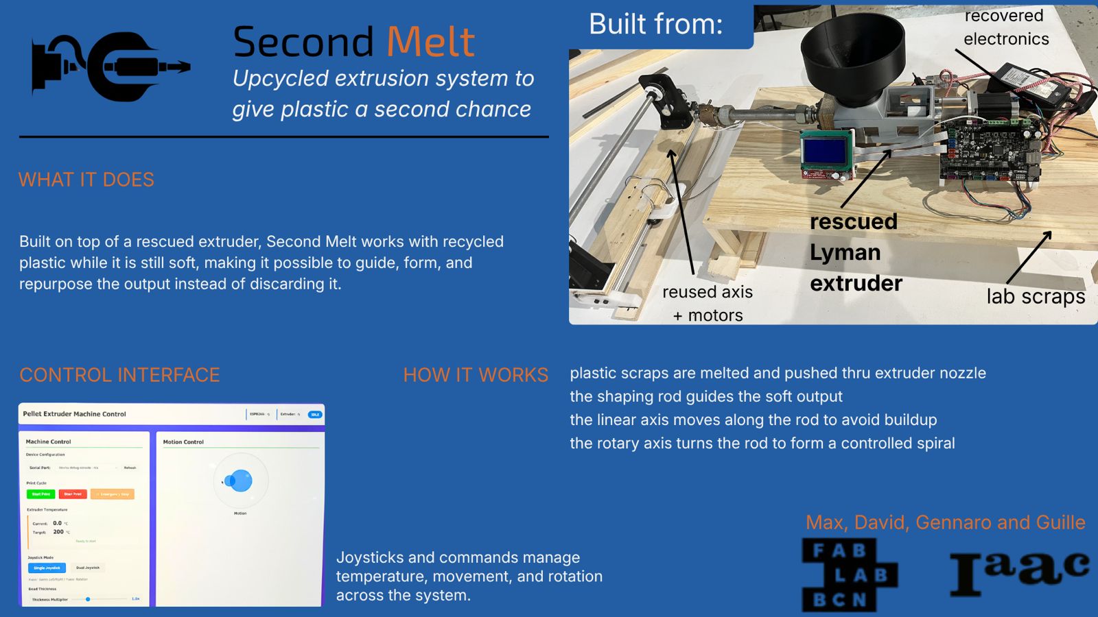
This group project builds on top of an existing plastic extruder already present in the lab.
Our goal was not to redesign the entire extruder, but to develop a complementary machine that could extend its functionality with a manageable scope for machine week.
The direction we selected was a post-extrusion shaping module placed after the nozzle. The intention was to interact with the plastic while it is still soft, before it fully hardens, and add a new functional step to the extrusion process.
What We Started From
Our first team discussion focused on defining the kind of machine we wanted to build.
We agreed on these non-negotiable criteria:
- keep it simple
- make it genuinely useful
- keep it feasible within the available time and effort
Based on those criteria, we decided to work on top of an existing plastic extruder proposed by Max.
The extruder is based on the Lyman extruder, an open-source filament extruder. The machine had originally been built years earlier by previous Fab Lab members and was later recovered by Max, who reorganized the system and rebuilt it as a working bench-top setup.
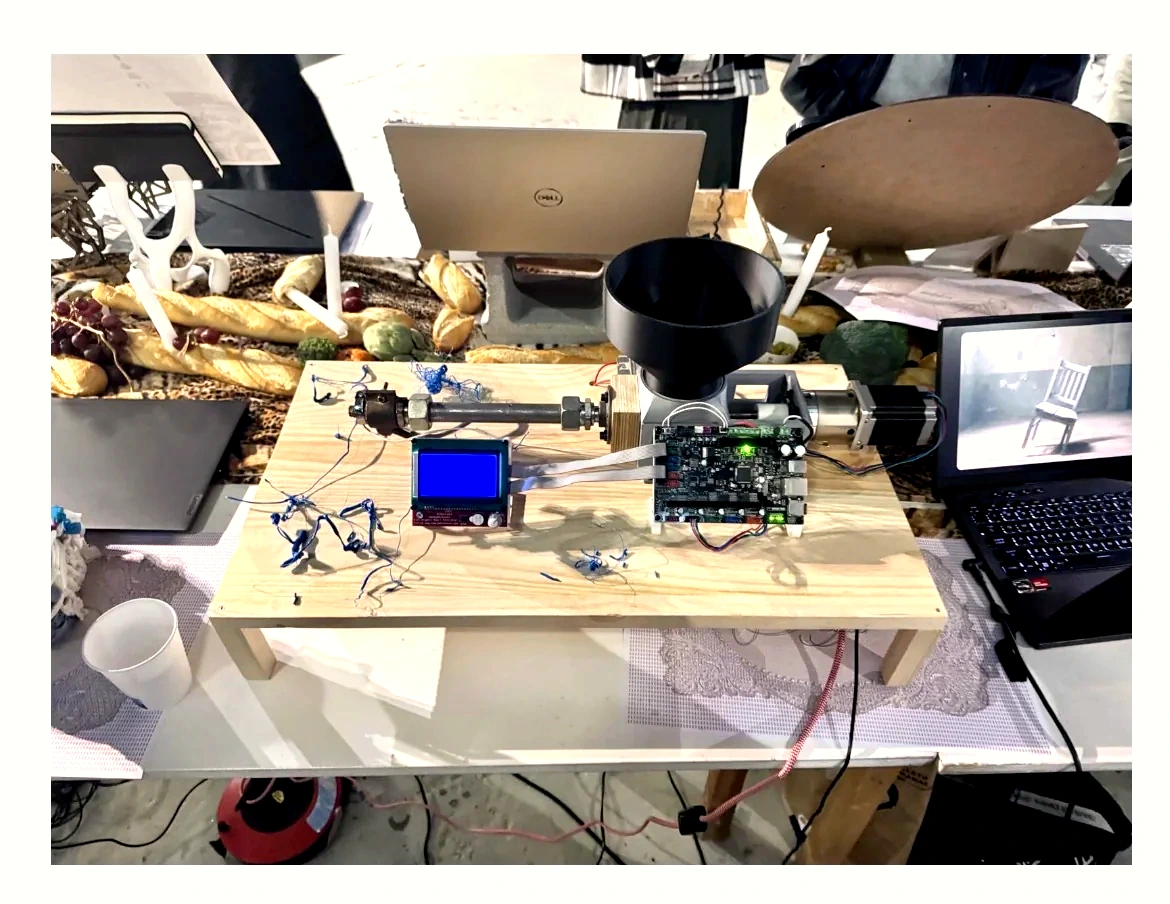
Recovered Lyman-based plastic extruder mounted on a wooden bench base. This existing machine became the starting platform for the group project.
What We Decided
Once the starting conditions were clear, we froze the project direction:
- build on top of the existing extruder
- avoid redesigning the full extrusion system
- create a mechanism that adds a new step after extrusion
- keep the system compatible with manual testing first and automation after
The concept selected by the team was a rotary shaping mechanism positioned after the nozzle.
This mechanism was intended to:
- receive the extruded material after it leaves the nozzle
- interact with it while still soft
- shape or guide the material before it fully hardens
What We Built — Mechanical Development
Linear Axis Structure
The first mechanical subsystem developed was the linear axis.
This assembly included:
- aluminum profile structure
- moving carriage
- belt transmission
- endstop switches
- stepper-driven motion base
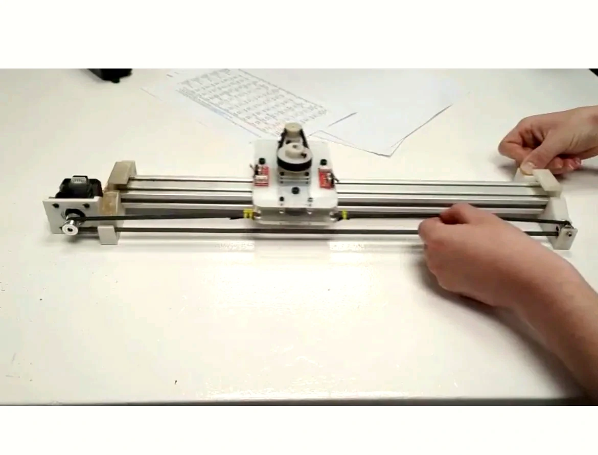
Top view of the first linear axis assembly, including carriage plate, guide rails, belt path, and limit switches.
Manual Motion Test
Before adding full actuation, we manually moved the mechanism to verify the basic behavior of the axis.
This test was used to check:
- smoothness of motion
- alignment of the carriage
- friction and play
- general mechanical feasibility
Manual motion test of the linear mechanism. This test was used to verify travel, smoothness, alignment, and the basic behavior of the axis before motorized control.
Motor Mount Design
To integrate the motor properly into the structure, a dedicated motor mount was designed.
The part was intended to provide:
- rigid support for the stepper motor
- alignment with the transmission system
- fastening points for assembly
- compatibility with the rest of the structure
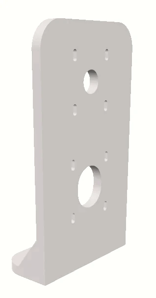
Perspective view of the motor mount CAD model.
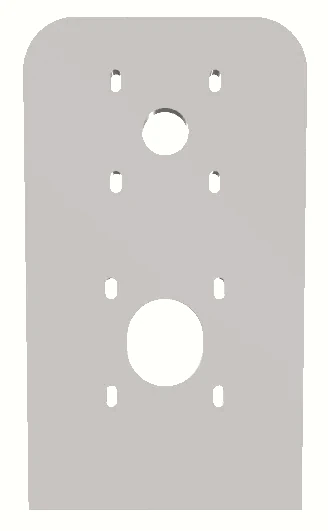
Front view showing the main openings and slotted fastening holes.
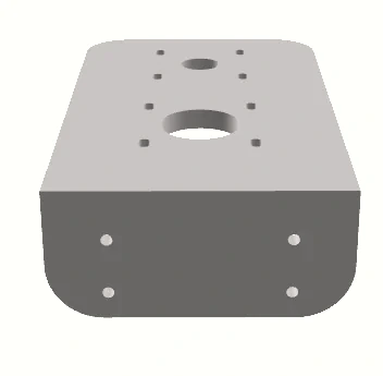
Bottom view showing the folded base geometry and mounting holes.
Fabricated Motor Mount
After the CAD design was defined, the motor mount was fabricated and checked physically against the structure.
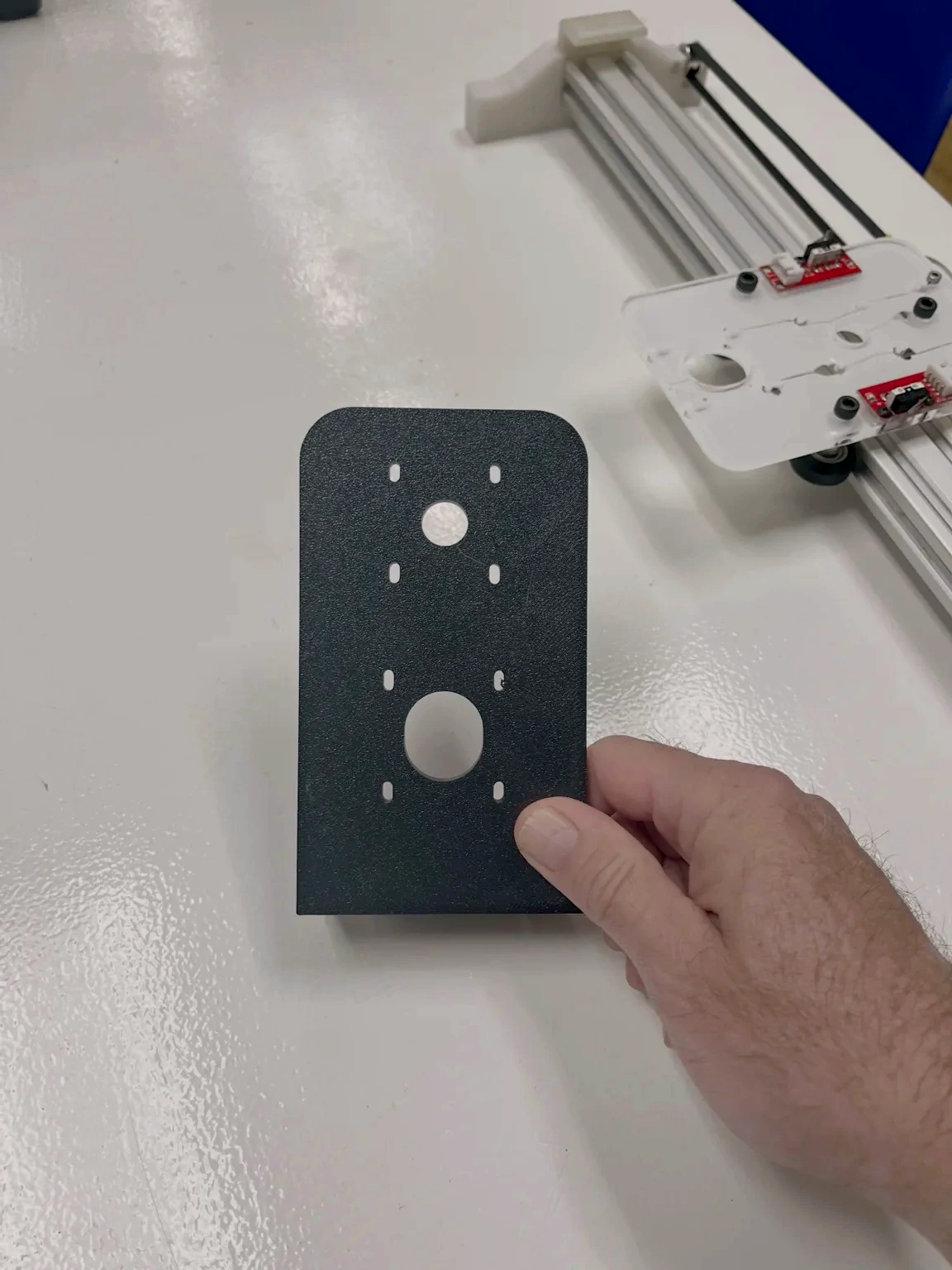
Fabricated motor mount plate produced from the CAD design and prepared for integration with the linear axis.
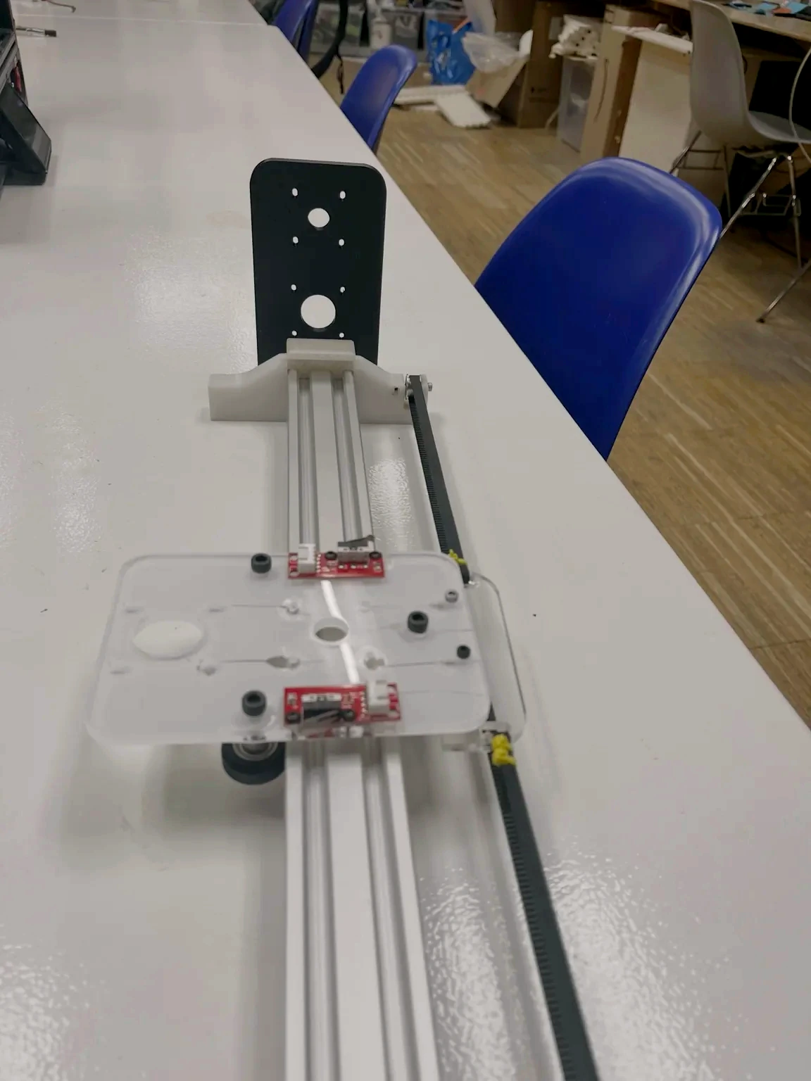
Motor mount installed on the axis structure to verify fit, alignment, and integration with the moving system.
Rotary Shaping Module
In parallel with the axis development, the shaping mechanism itself was developed as a rotary subsystem.
This module included:
- stepper motor
- pulley system
- belt transmission
- rotating output wheel
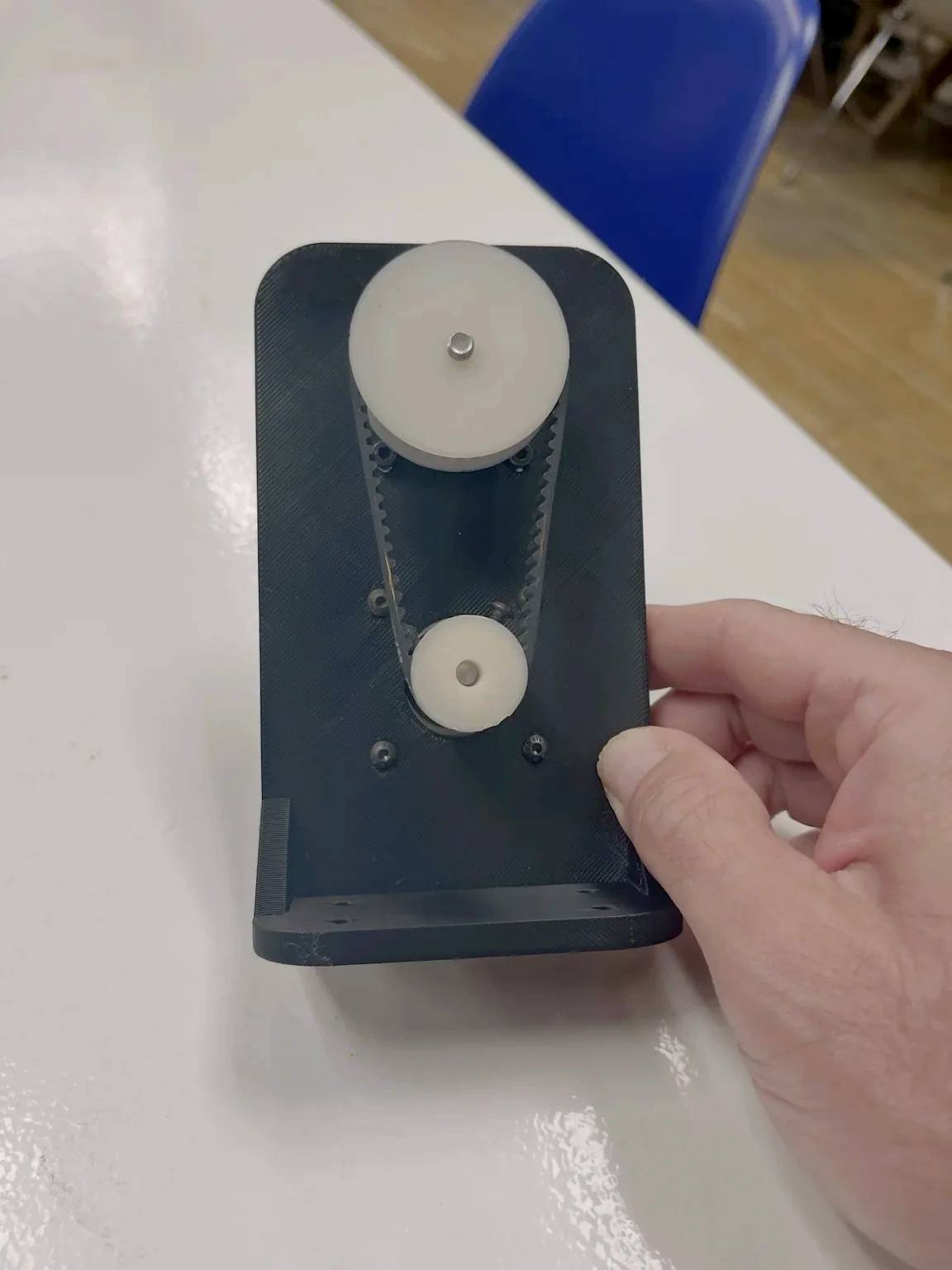
Front view of the rotary shaping module, including stepper motor, pulley system, and belt transmission.
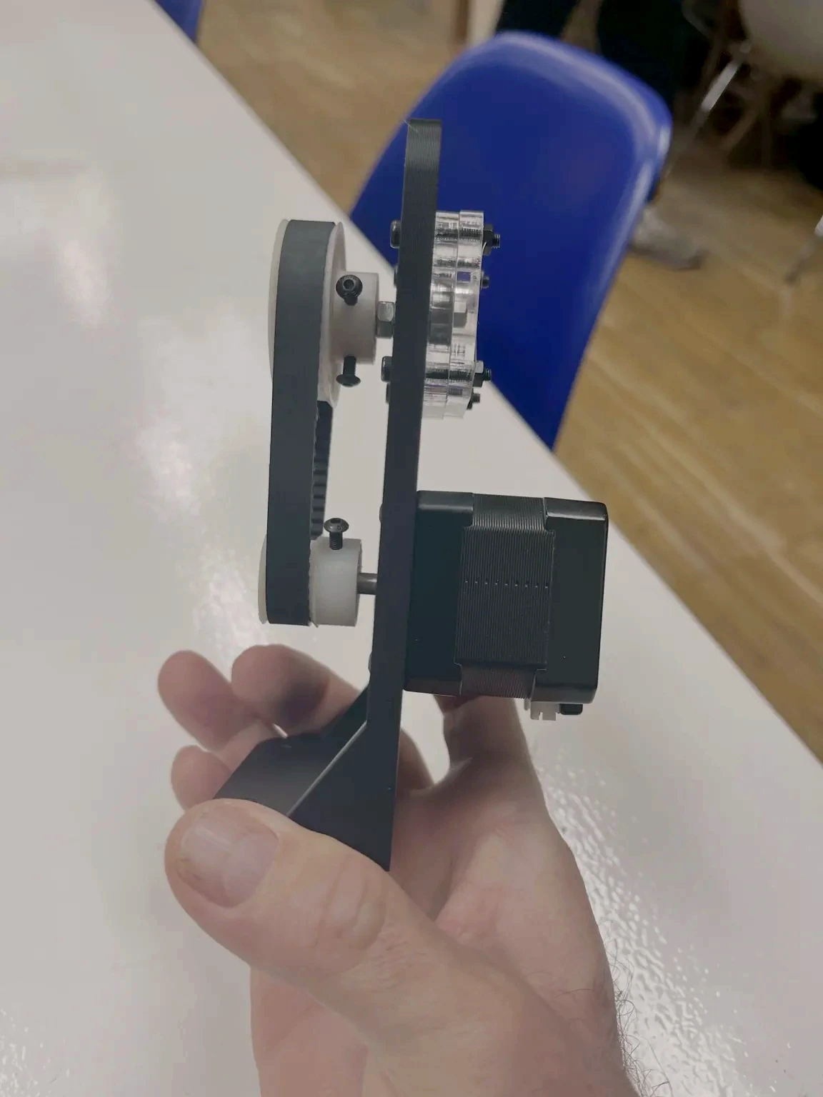
Side view of the rotary shaping module showing the relationship between motor, transmission, and output wheel.
How We Controlled It — Electronics and Control
To actuate the machine, we assembled a small control system around a microcontroller, driver modules, and power regulation.
The electronics work focused on:
- driving the stepper motor
- reading the endstop switches
- powering the control system safely
- preparing the machine for automated motion
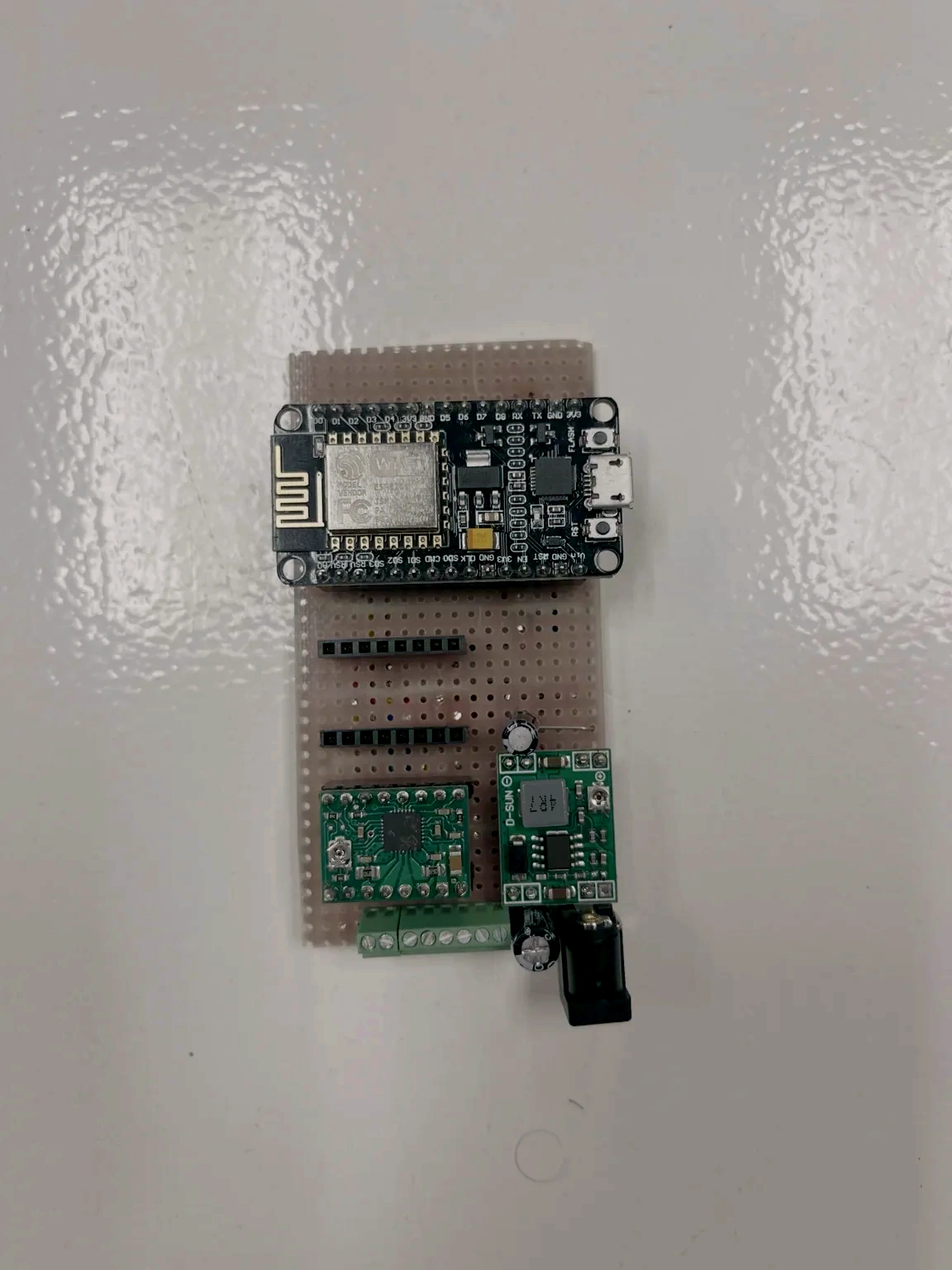
Initial control board assembly used to interface the microcontroller, driver, and power electronics for the motion system.
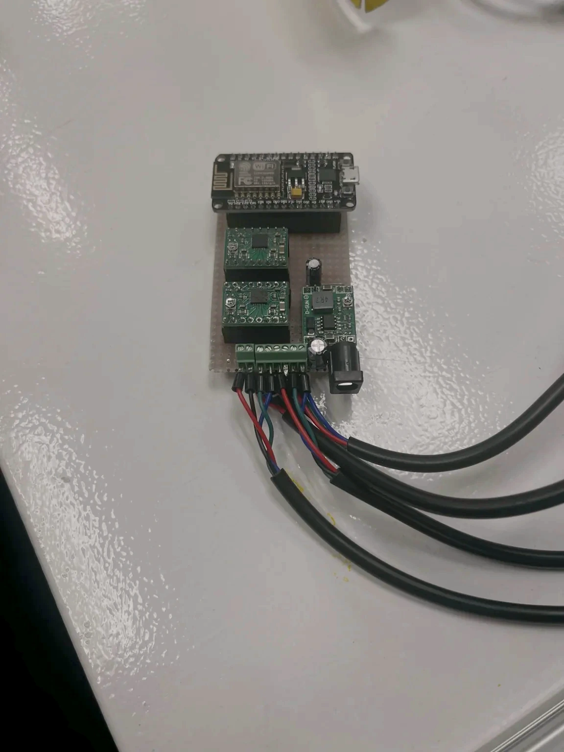
Close-up of the control board with microcontroller, motor driver modules, power regulation, and terminal connections.
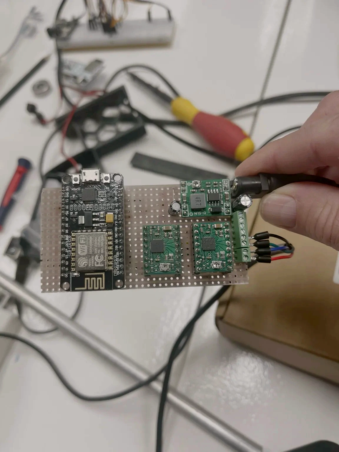
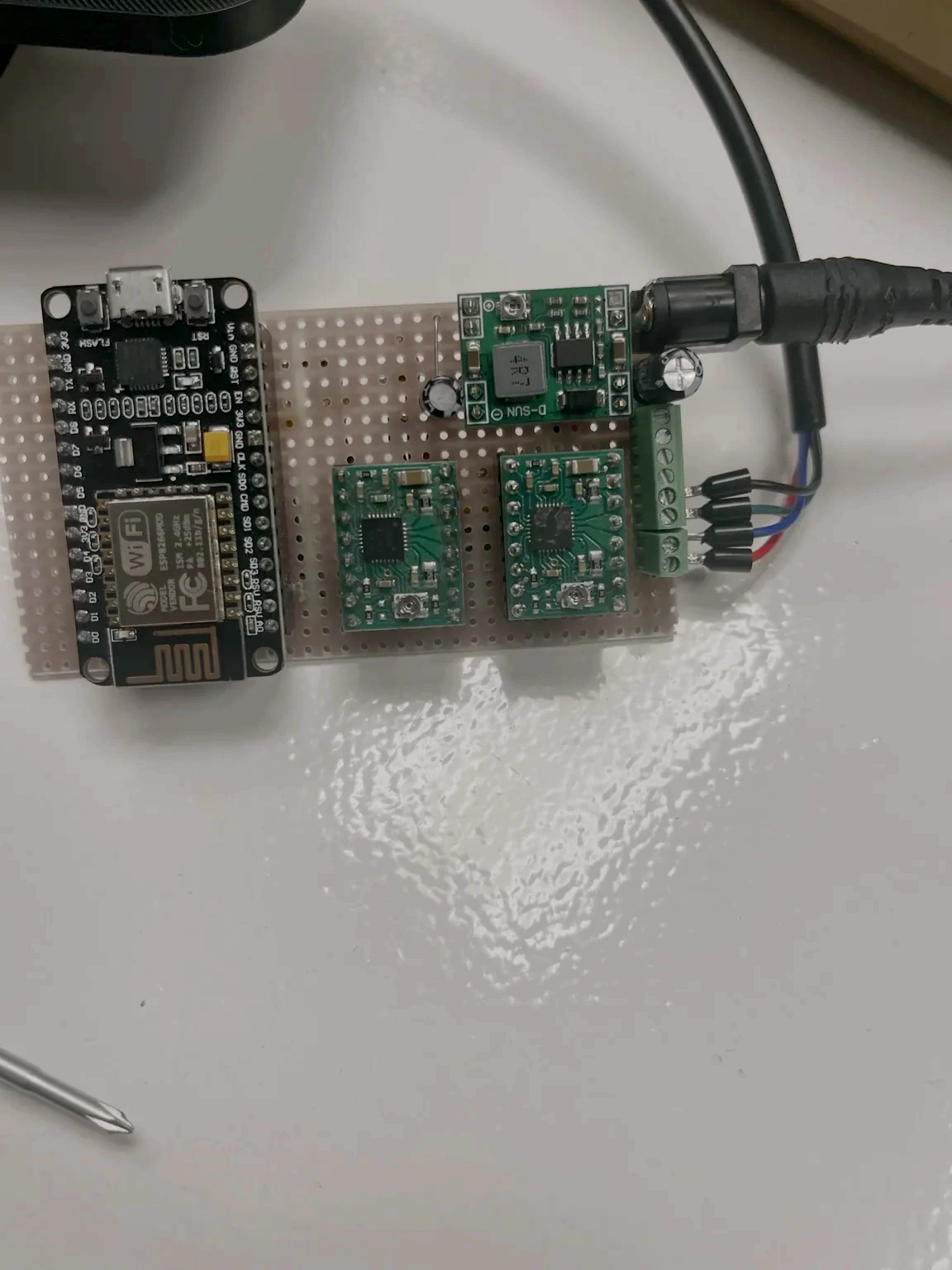
Handheld view of the assembled control board during testing and wiring checks.
Control board connected and wired for operation, ready to drive the motion system and read the sensors.
Putting everything together
As the project moved forward, the different parts of the machine were laid out together on the worktable to review progress, check compatibility, and prepare for integration.
This layout included:
- the linear motion axis
- electronics and control components
- structural profiles
- rotary and transmission-related parts
- mounting hardware and small mechanical components
- tools and materials still being used during assembly
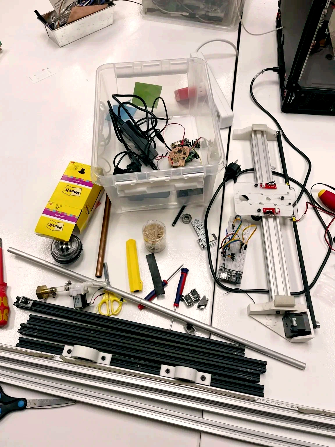
Workbench view of the project during development, showing the machine as a collection of evolving subassemblies and components before final integration.
How We Tested It
First Motor Activation Test
Once the electronics were connected, we tested the basic on/off behavior of the motor.
This helped verify:
- the controller was powering correctly
- the driver could actuate the motor
- the signal path between board and motor was working
- the machine could move under powered control
Initial motor activation test used to confirm the electronics, driver, and actuation system could power the mechanism reliably.
At this stage, the system included the structural axis, carriage, transmission, and endstop switches needed for positional reference.
Homing Sequence Test
After confirming powered motion, we tested the homing sequence.
This was an important milestone because it showed that the machine could:
- move automatically toward a known reference
- detect the endstop correctly
- stop at a repeatable point
- establish a zero position for automated operation
Automated homing sequence of the machine. The carriage moves toward the limit switch, detects a known reference position, and establishes a repeatable zero point for operation.
Post-Extrusion Material Test
To define the shaping mechanism, we observed the material directly at the extruder output.
This early test focused on the moment when the plastic leaves the nozzle and is still soft and deformable.
The goal was to understand:
- how the extruded material behaves immediately after exiting the nozzle
- how much working time is available before it hardens
- how the material can be guided or shaped during that transition phase
- what type of post-extrusion mechanism can interact with it effectively
This test became an important turning point in the project because it linked the existing extruder to the new machine concept through direct observation of the material itself.
It gave us a way better understanding of what the shaping add-on mechanism looked like as after the extrusion output.
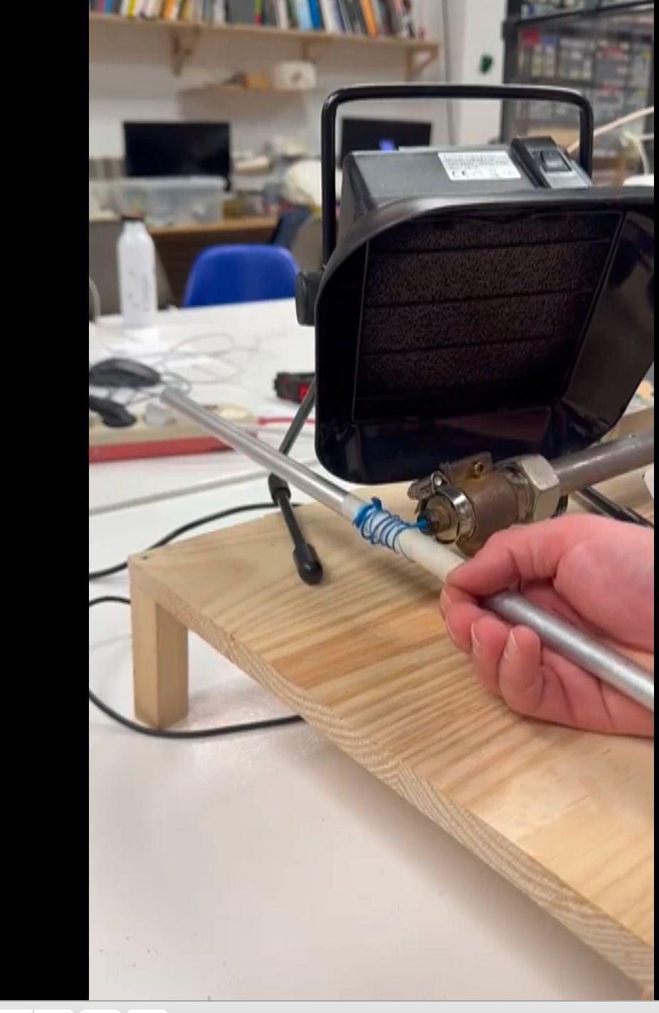
*Initial post-extrusion test showing the material as it leaves the nozzle and is manually guided while still soft.
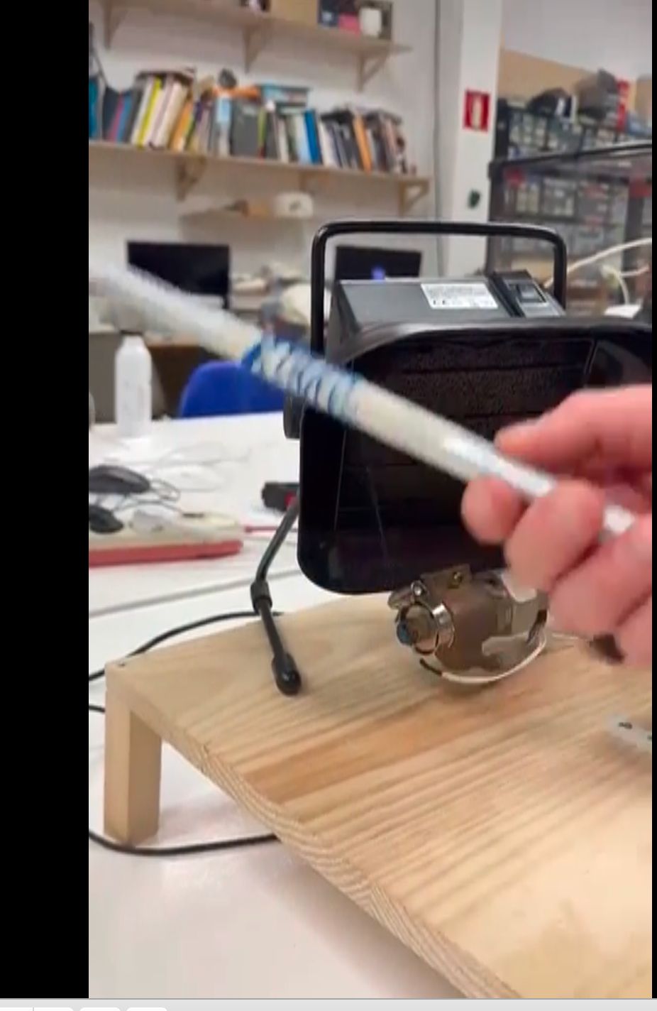
This observation helped define the need for a shaping mechanism positioned after the extruder output.*
Control Interface
To operate the prototype as one coordinated system, we developed a custom control interface that combines extrusion and motion settings in one place.
The interface includes:
- machine start and stop actions
- temperature control for the extruder
- joystick-based motion input
- control of linear movement and rotation
- a simple operator view for testing and adjustment
This made it possible to manage the system as a single machine rather than as separate subsystems.
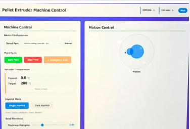
Custom interface used to manage temperature, movement, and rotation across the system.
Material Source
For the shaping tests, we used shredded blue plastic from failed Smart Citizen enclosure prints.
Instead of discarding these bad prints, the material was recovered, processed into feedstock, and reused in the extruder. This connected the circularity of the project not only to the machine itself, but also to the plastic being tested.
Early Shaped Output
The first shaping tests produced blue spiral samples from recycled plastic.
These outputs showed that the system could move the shaping rod along the axis while rotating it, preventing material buildup near the nozzle and forming the extrusion into a controlled coil. Although still experimental, these first samples validated the core idea behind the machine.
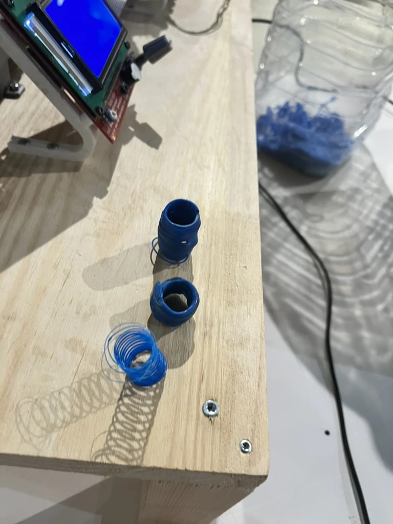
Early spiral samples produced from recycled Smart Citizen prints by guiding and rotating the soft extrusion after the nozzle.
Project Poster
This is the poster we shared at the Global Review
Project Video
A one-minute project video was produced to summarize the machine concept, circular build strategy, interface, and shaping results.
Problems and Adjustments
During development, several issues had to be resolved:
- alignment between the extruder output and the shaping rod
- material buildup near the nozzle during shaping tests
- integrating reused subsystems that were not originally designed to work together
Reflection
This project applied circularity at two levels: reused plastic as feedstock, and reused machine parts as the system that processes it.
Second Melt reused failed prints as material and recovered components as structure, motion, and control. The result is still an early prototype, but it demonstrated that soft plastic can be shaped after extrusion and that abandoned subsystems can be integrated into a new working machine.
Use of AI
AI tools were used throughout the project as support for planning, documentation, interface development, and visual communication.
These tools were used to:
- structure the project documentation and improve clarity
- refine captions, section flow, and technical explanations
- assist with the development of the control interface code
For the control interface specifically, Claude Code was used as a coding assistant during the development of the machine control interface. It supported the implementation and refinement of the interface logic, including the layout and behavior of the virtual joystick controls used to manage movement, rotation, and temperature across the system.
AI was used as a design and development support tool, but all final decisions, fabrication, integration, testing, and documentation editing were carried out by the team.