Week 07 — Computer Controlled Machining
Global Class
This week’s global session brought together two complementary perspectives on machining.
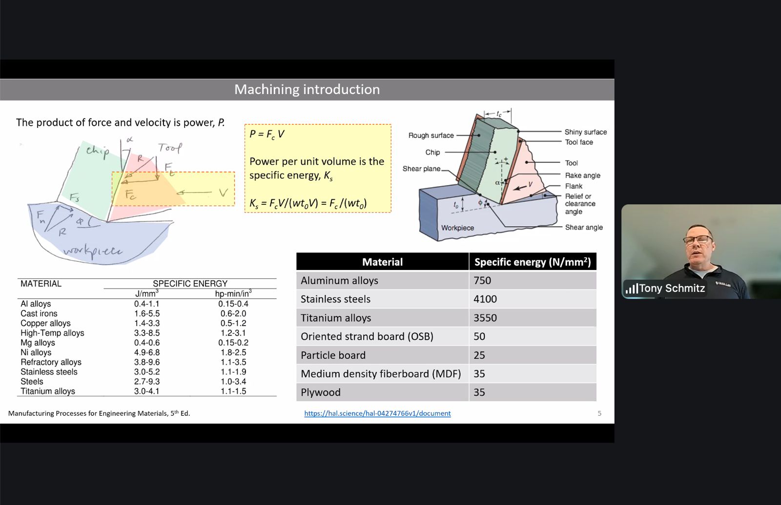
Tony Schmitz introduced the fundamentals of CNC machining from an engineering and manufacturing perspective.
Tom Bodett, a lifelong woodworker and founder in Vermont, followed with a craftsman’s view on how digital fabrication fits within traditional woodworking practices.
Computer controlled machining is a subtractive manufacturing process using a rotating cutting tool.
As the tool moves through the material it shears away small fragments called chips, gradually shaping the final object according to the digital design.
As Tony Schmitz put it, machining is a competition between the tool and the material — and in the end, the material always wins.
Because of these physical constraints, successful machining depends heavily on choosing the correct parameters, commonly referred to as speeds and feeds. These determine how aggressively the tool interacts with the material and strongly affect surface quality, machining time, and tool lifespan.
The most important parameters include:
- cutting speed — the velocity of the cutting edge relative to the material
- feed rate — the speed at which the tool advances through the material
- chip load — the thickness of material removed by each cutting tooth
The machines typically used in Fab Labs are 3-axis CNC routers. More advanced systems may add rotational axes, enabling 4-axis or 5-axis machining, which allows complex geometries and surfaces to be produced.
Another important aspect of machining is the direction of milling.
Up milling (conventional milling) begins with a near-zero chip thickness that gradually increases during the cut. Down milling (climb milling) begins with the maximum chip thickness and decreases as the tool exits the material. Down milling often produces smoother surface finishes because the cutting force reduces toward the end of the cut.
Tom Bodett’s perspective added an important reminder: CNC machines are extremely powerful tools, particularly when producing large structures or repeated parts. However, machining itself is only part of the making process. The CNC machine removes the bulk of the material and produces precise shapes, but the craft continues afterwards through finishing, sanding, assembly, and detailing.
In other words, when the machine stops cutting, the real making often begins.
Local Class
Introduction to CNC machining
The local session focused on understanding CNC machining workflows and the preparation steps required before operating the machine.
CNC machining provides higher dimensional precision compared to processes such as laser cutting or 3D printing. Tolerances are tighter and parts can be produced with greater structural accuracy.
A rule of thumb introduced during the session was that machining projects are typically divided into three equal phases:
1/3 design
1/3 machining
1/3 post-processing
This highlights that time must be distributed across design preparation, machine operation, and finishing work.
CAM Setup in RhinoCAM
During the local session we focused on preparing toolpaths using RhinoCAM.
The workflow starts by selecting the appropriate cutting tool and defining machining parameters such as spindle speed, feed rate, and tool geometry.
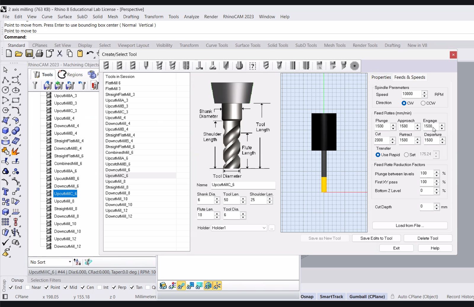
This step is critical because the selected tool defines how material will be removed. The diameter, flute length, and cutting parameters influence cutting forces, surface finish, and machining time.
Defining the Stock
Before generating toolpaths the material stock must be defined.
This step establishes the size and position of the raw material block that the CNC machine will remove material from.
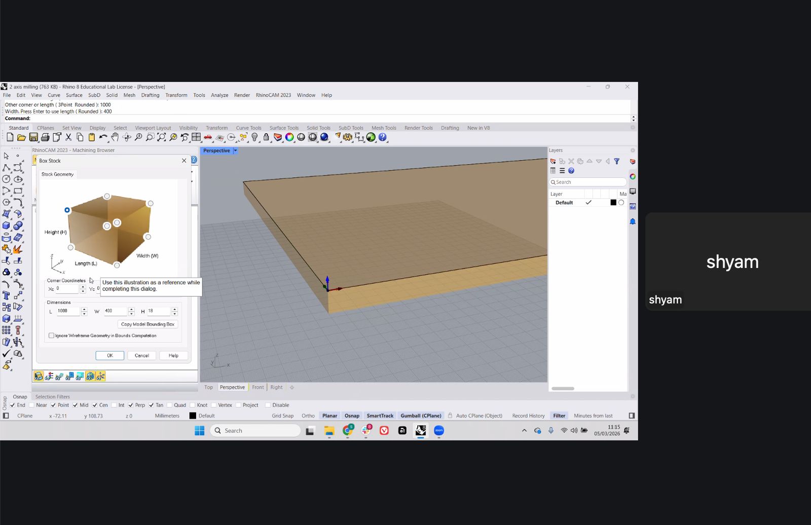
In this case the stock was defined as a rectangular board matching the dimensions of the plywood sheet we plan to machine.
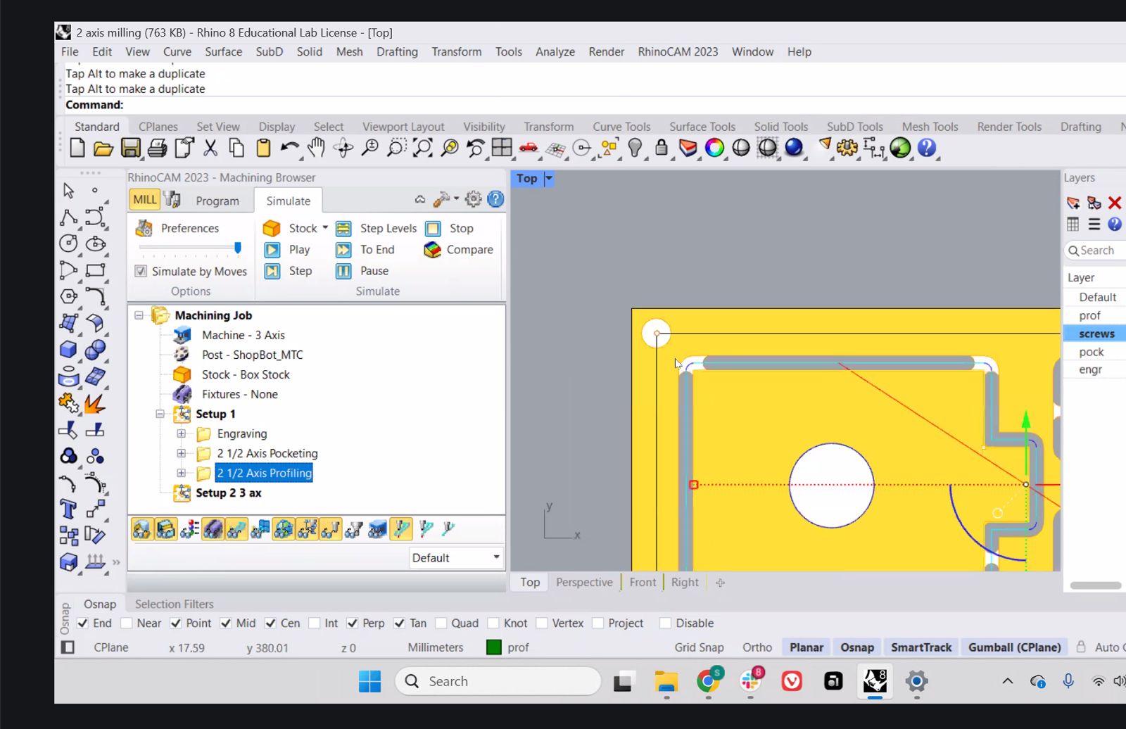
Selecting Machining Regions
Once the stock is defined, the next step is selecting the regions that will be machined.
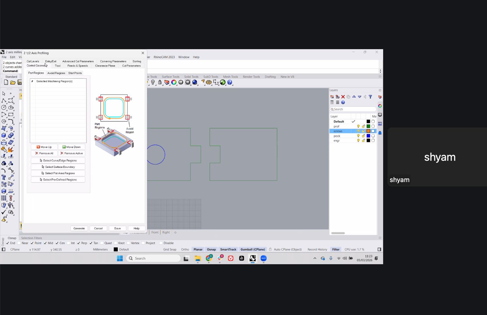
Different layers were used to organize the machining operations:
- profiling
- screws / hold-down points
- pocketing
- engraving
Separating geometry into layers makes the CAM workflow easier to control and debug.
Profiling Toolpath
The profiling operation defines the outer contour of the part.
This toolpath is usually executed last, once all internal machining operations are complete.
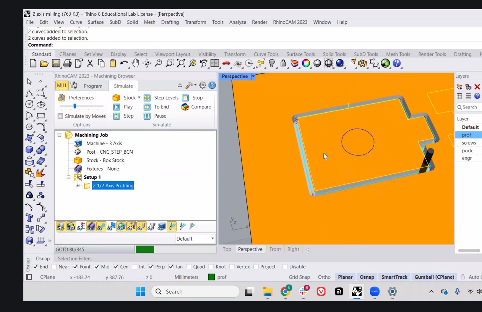
Tabs or bridges can be added to prevent the part from moving during the final cut.
2.5 Axis Machining Strategy
The example used a 2.5-axis machining approach, where the tool moves in X and Y while stepping down incrementally in Z.
This approach is common for CNC routers working with sheet materials such as plywood.
3-Axis Machining
For more complex geometries the workflow can move to full 3-axis machining, where the tool follows curved surfaces.
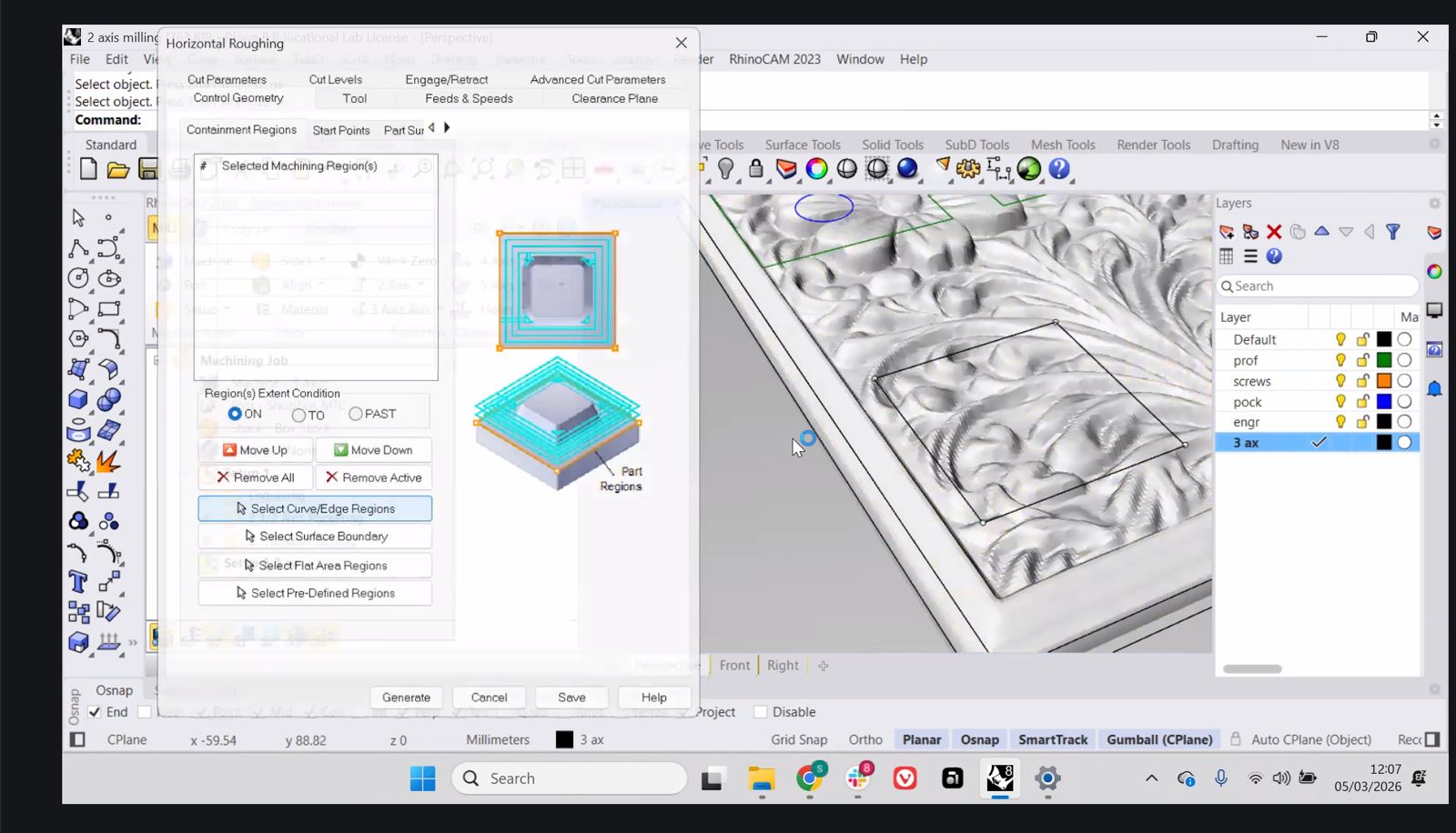
In this case the toolpath begins with roughing passes to remove large volumes of material.
Roughing and Finishing
The final step demonstrated a typical workflow used in 3-axis machining:
- horizontal roughing to remove most of the material
- parallel finishing passes to achieve the final surface.
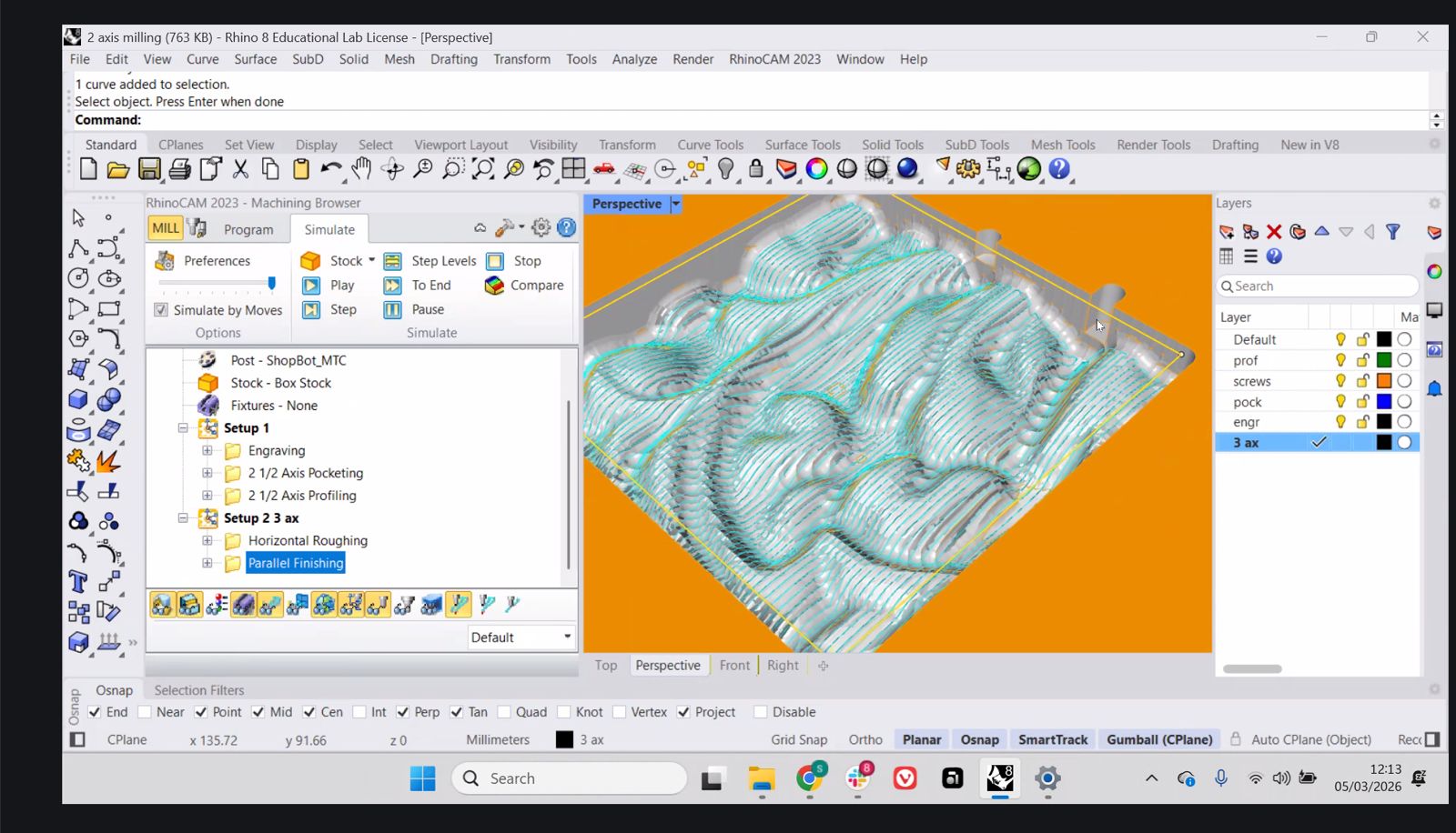
Finishing operations typically use smaller stepovers (around 20–25% of tool diameter) to achieve smoother surface quality.
Material
Each student receives a single sheet of material for the assignment.
The typical Fab Lab sheet size is approximately:
1220 mm × 2440 mm
For the assignment the design should occupy roughly a 1 meter by 1 meter area of the board to demonstrate the use of large format CNC machining.
Group Assignment
Here is the work we did for the group assignment:
Learnings & Reflections
- CNC machining depends on correct selection of speeds, feed rate, and chip load, which directly affect cut quality and tool life.
- Toolpath strategy (profiling, pocketing, roughing, finishing) determines both machining efficiency and final surface quality.
- Defining stock and machining regions correctly is essential to avoid errors and ensure predictable results.
- Workholding methods such as screws and tabs are critical to prevent material movement during cutting.
- Understanding the full workflow from CAD to CAM to machine operation is necessary before running the CNC.
- Reinforced that machining is not only cutting, but also includes planning, setup, and post-processing.
Individual Assignment
Project Overview
For this week, instead of continuing development of the final project, I focused on a real-world fabrication problem: replacing a broken sink cabinet at home.
The decision is based on previous work done during Week 3, where a full-scale prototype of the structure was already fabricated and tested.
Goal
Design, mill, and assemble a replacement cabinet structure using CNC machining.
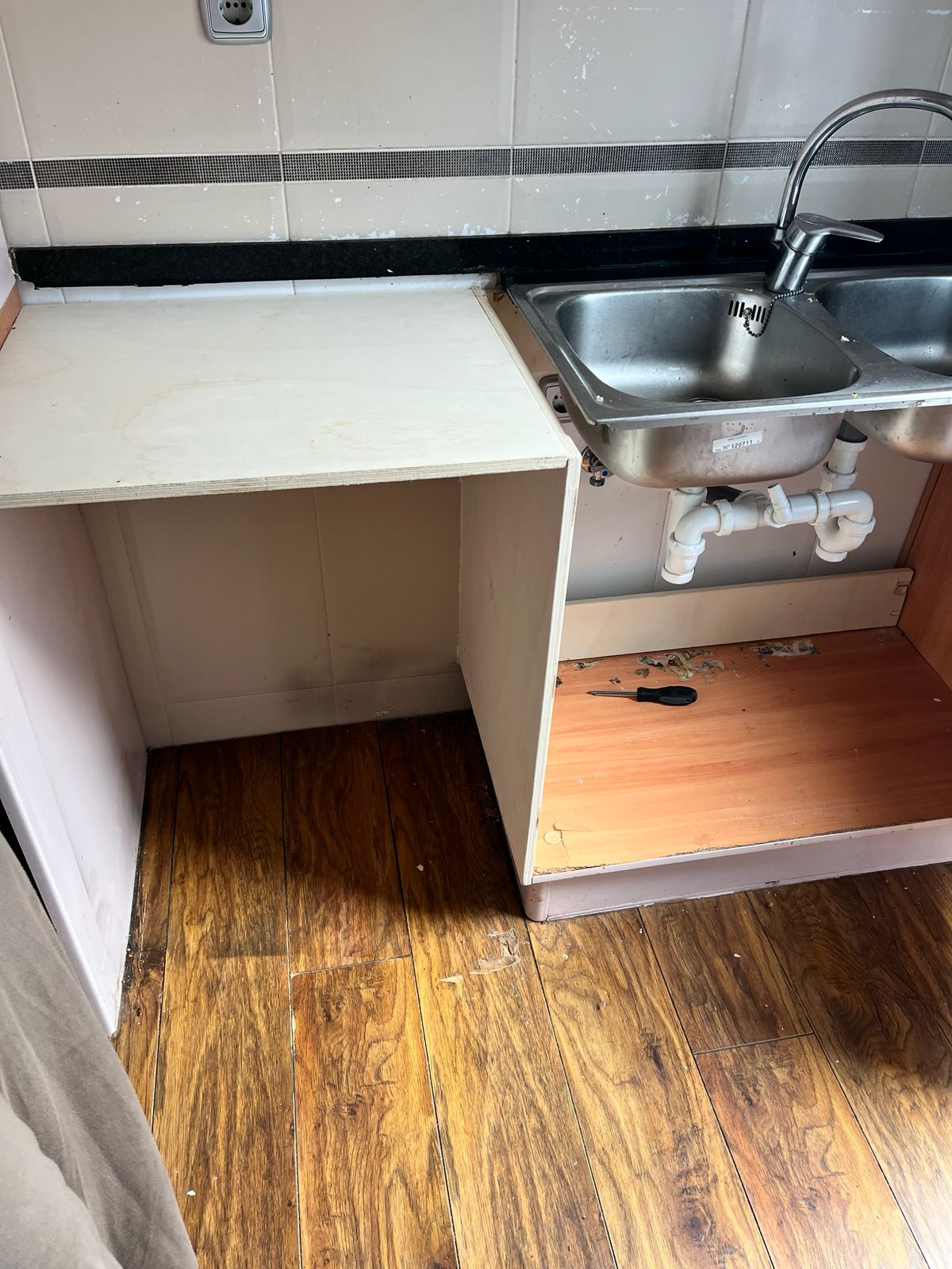
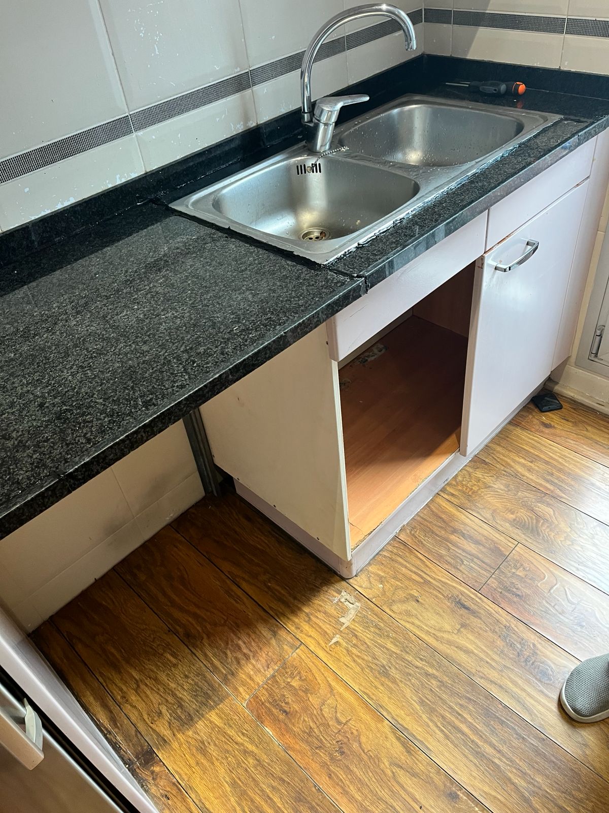
Initial Condition
The original cabinet was damaged and in bad shaped due to termites and cockroaches.
Issues observed:
- broken panels
- degraded particle board
- poor structural integrity
- water damage near edges
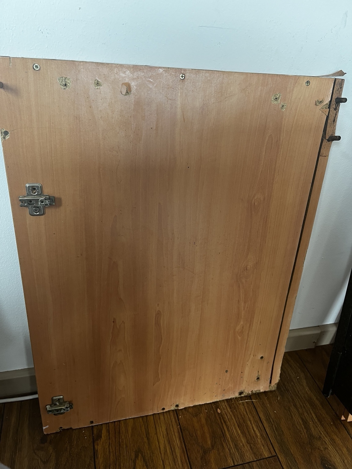
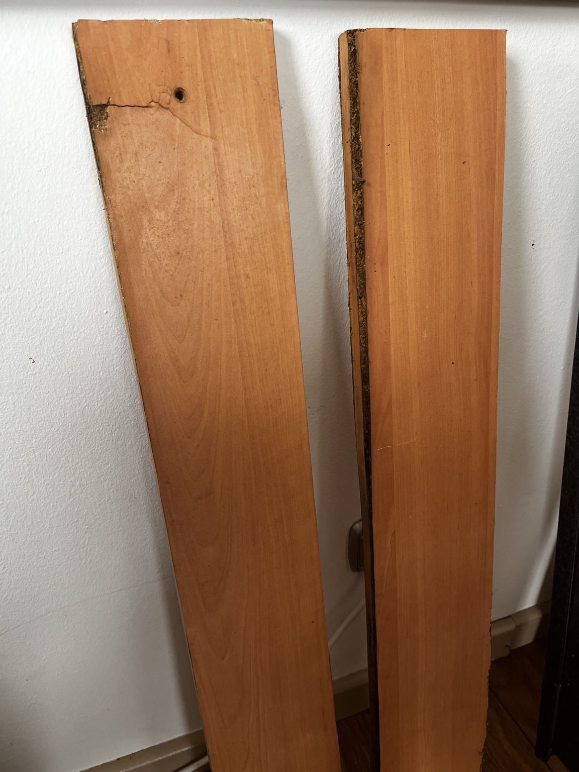
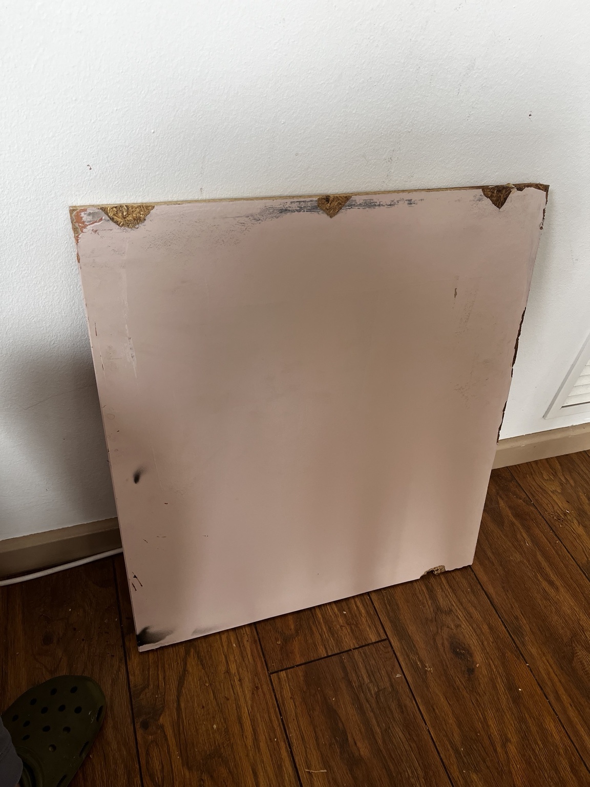
The damaged cabinet was disassembled so the reusable dimensions and hardware positions could be understood.
Design
The existing cabinet was measured manually and sketched before moving into CAD.

From the existing cabinet, I identified the main elements needed for the replacement:
- main door / front panel
- side or support panels
- rear structural supports
- hinge and fastening locations
CAD Development
The cabinet was simplified into flat panels suitable for CNC machining.
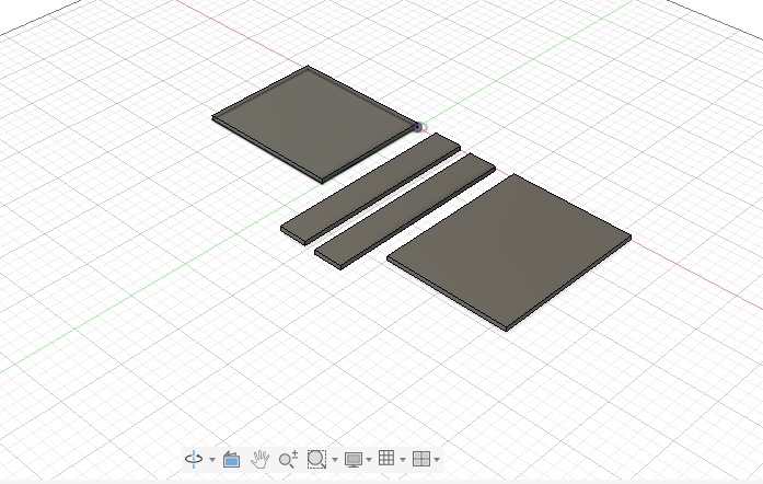
Key considerations:
- use flat panel geometry for 2.5D machining
- keep parts simple and easy to assemble
- preserve the main dimensions of the existing cabinet
- avoid unnecessary complexity in the first version
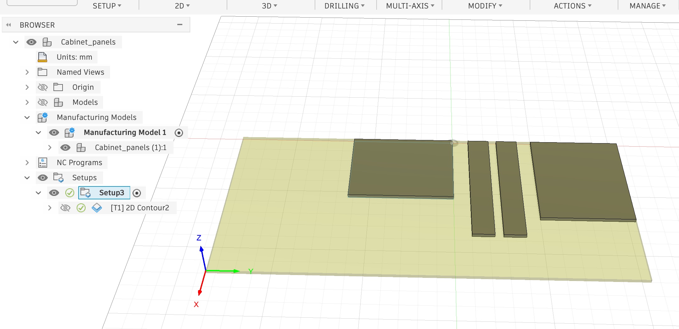
CAM Workflow
Toolpaths were generated using Fusion 360.
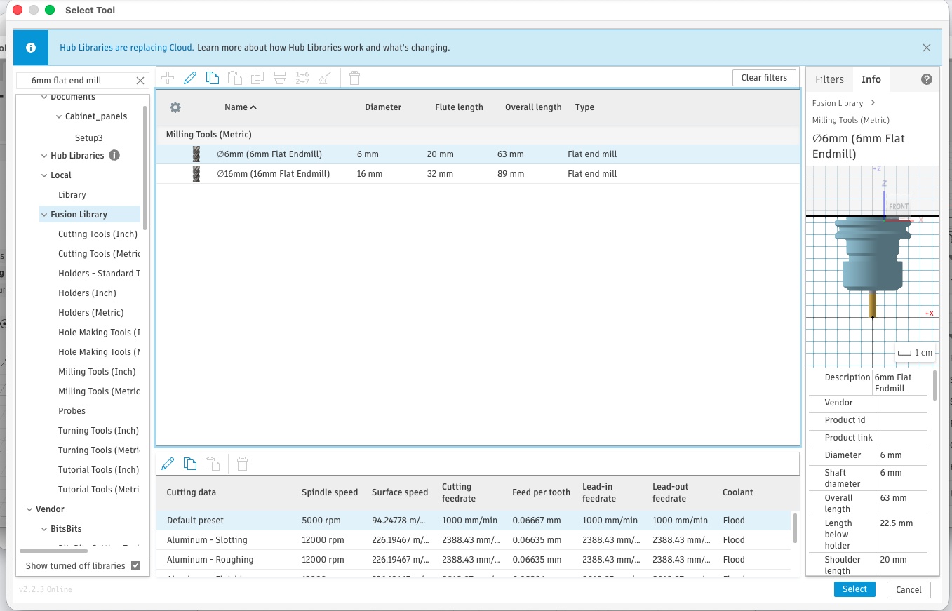
Tool Selection
- 6 mm flat end mill
Operation
- 2D contour cutting
The CAM setup defined:
- stock size
- work origin
- tool selection
- cutting operation
- toolpath preview
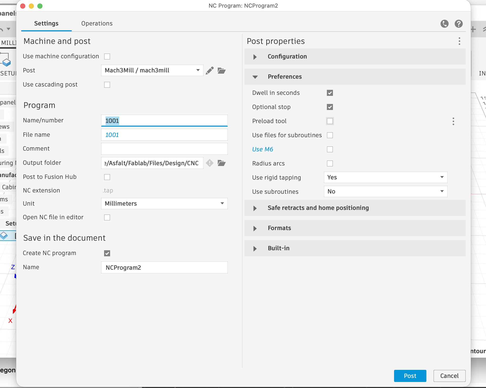
Post Processing
The toolpath was post-processed to generate the machine file.
CNC Workflow Adaptation
The initial CAM workflow was developed in Fusion 360, but the Raptor CNC machine operates with RhinoCAM. This created a compatibility issue, as Fusion toolpaths could not be used directly on the machine.
To resolve this, the workflow was adapted by separating design from fabrication:
Fusion was used only for geometry, exporting clean 2D contours as a DXF file. The CAM process will later be rebuilt in RhinoCAM on the lab computer.
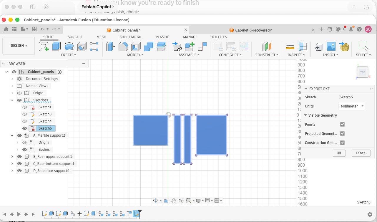
Key steps included:
- projecting 3D bodies into a 2D sketch in Fusion
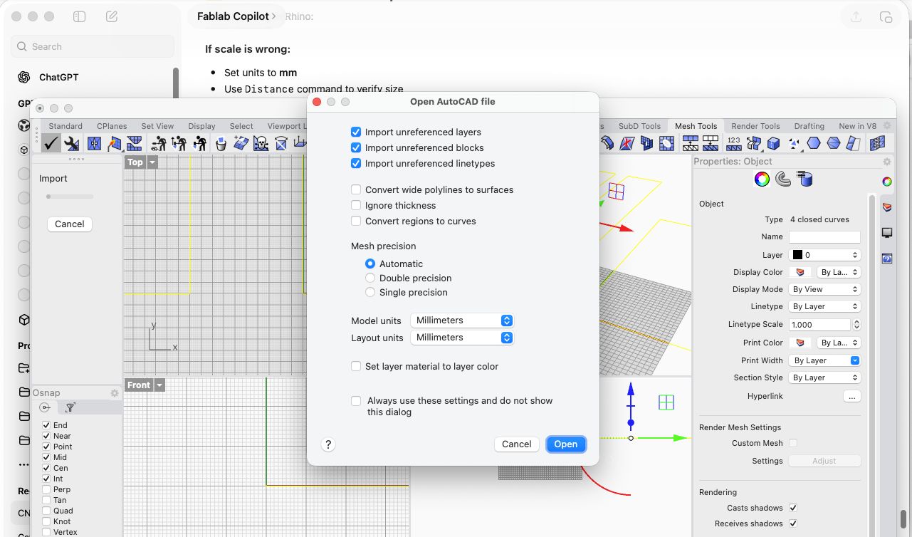
- exporting a clean DXF file
- importing into Rhino and fixing geometry (Z alignment, closed curves, duplicates)
- preparing the file for RhinoCAM toolpath generation
This highlighted that CNC workflows are machine-dependent, and that using neutral formats like DXF is something to consider previously when moving between different CAM environments.
CNC CAM in RhinoCAM
After preparing and cleaning the geometry in Rhino, the CAM workflow was executed in RhinoCAM on the lab computer.
Setup
A new machining job was created using a 3-axis configuration. The correct post-processor for the Raptor CNC was selected to ensure compatibility with the machine.
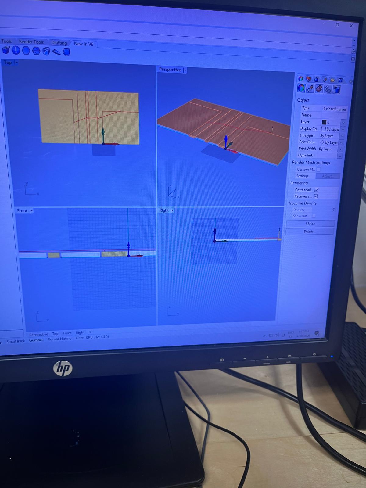
Stock Definition
A box stock was defined representing the plywood sheet.
- Stock type: Box
- Top surface aligned to Z = 0
- Thickness set to real material (~15 mm measured)
- XY dimensions based on sheet size or bounding box
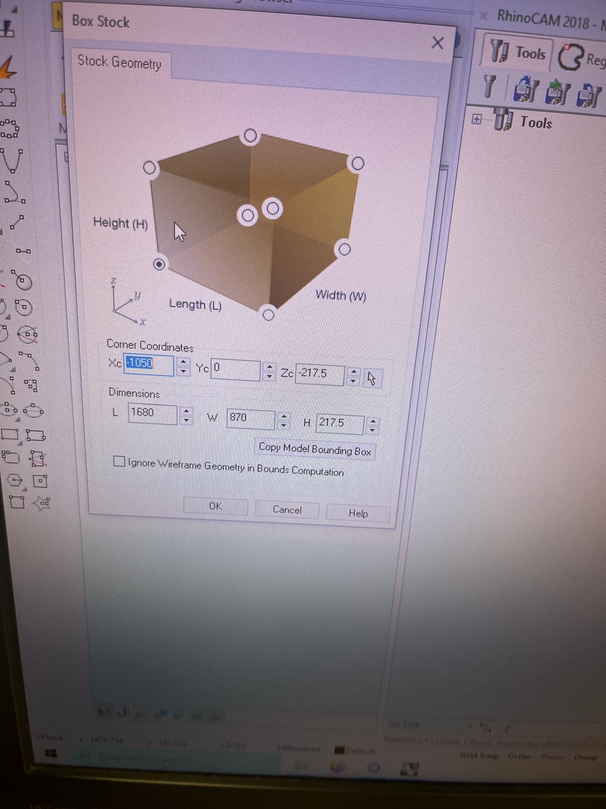
This step ensures that all cutting operations reference the real material correctly.
Tool Definition
A flat end mill was defined:
- Diameter: 6 mm
- Spindle speed: 18000 RPM
- Feed rate: ~2600–3000 mm/min
- Plunge rate: ~800–2600 mm/min
- Step-down: ~3–4 mm
These were the parameters chosen to ensure safe cutting on plywood.
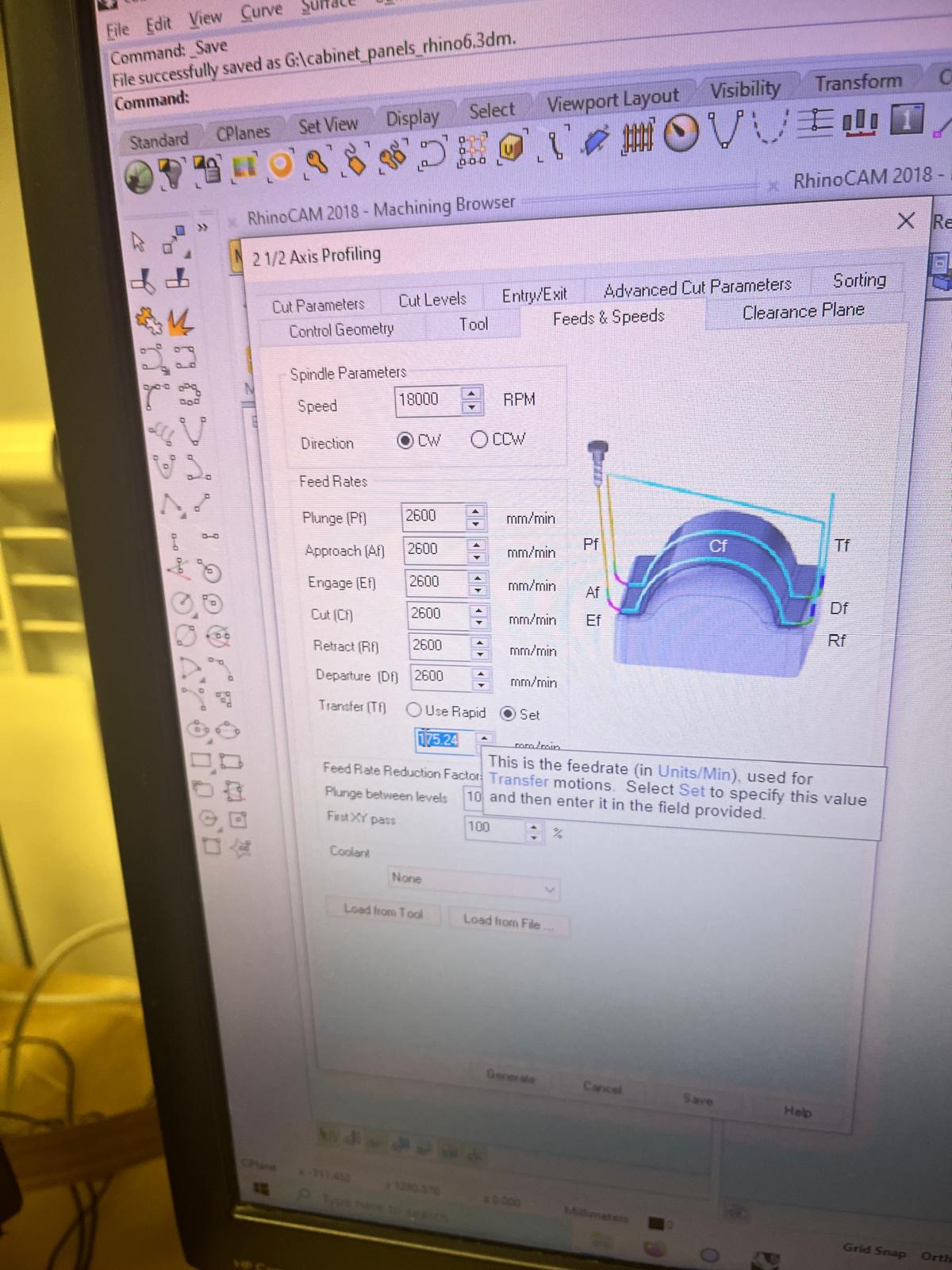
Profiling Operation
A 2.5 Axis Profiling operation was created to cut the panel outlines.
Key parameters:
- Geometry: outer contours of panels
- Cut side: outside
- Start level: Z = 0
- Total cut depth: material thickness (~15.3 mm)
- Step-down: ~3.1 mm per pass
Multiple passes were generated to progressively reach full depth.
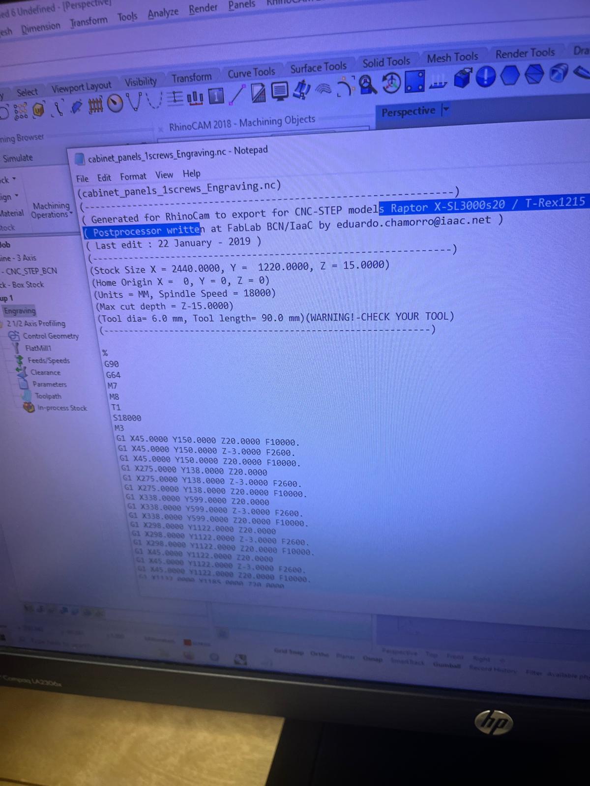
Screws / Engraving Operation
An additional operation was created to mark or pre-drill screw positions:
- Shallow depth engraving
- Same tool used
- Lower depth to avoid cutting through material
This allows precise placement of screws during assembly.
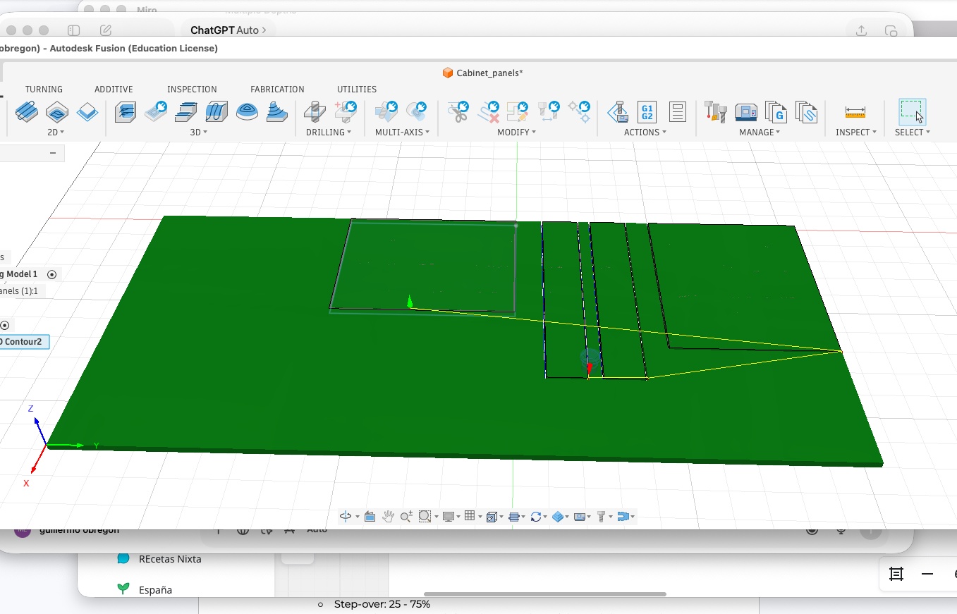
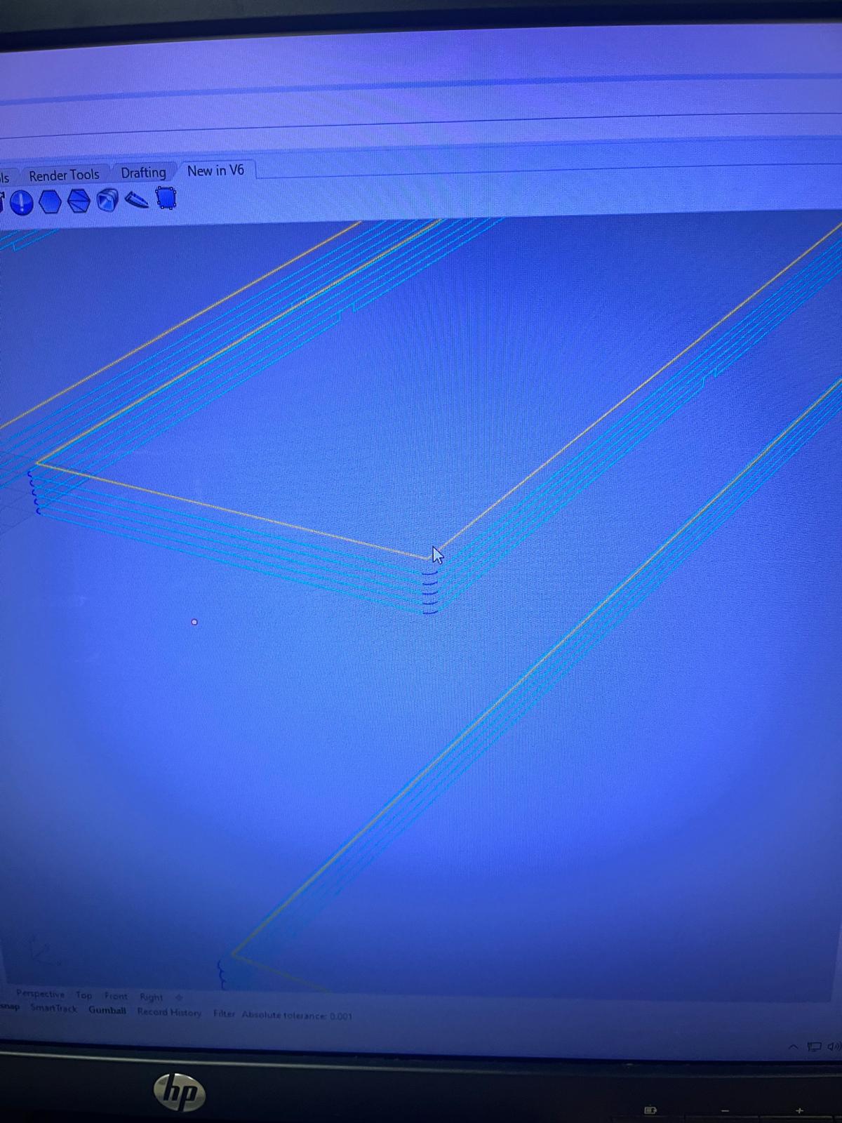
Toolpath Visualization
Toolpaths were generated and visualized in Rhino:
- Verified correct cutting direction
- Checked full depth coverage
- Confirmed geometry alignment with stock
Post-Processing
Toolpaths were exported using the Raptor-compatible post-processor.
Two files were generated:
- Panel cutting file (
cabinet_panels_2_2 Axis Profiling.nc) - Screw marking file (
cabinet_panels_1screws_Engraving.nc)
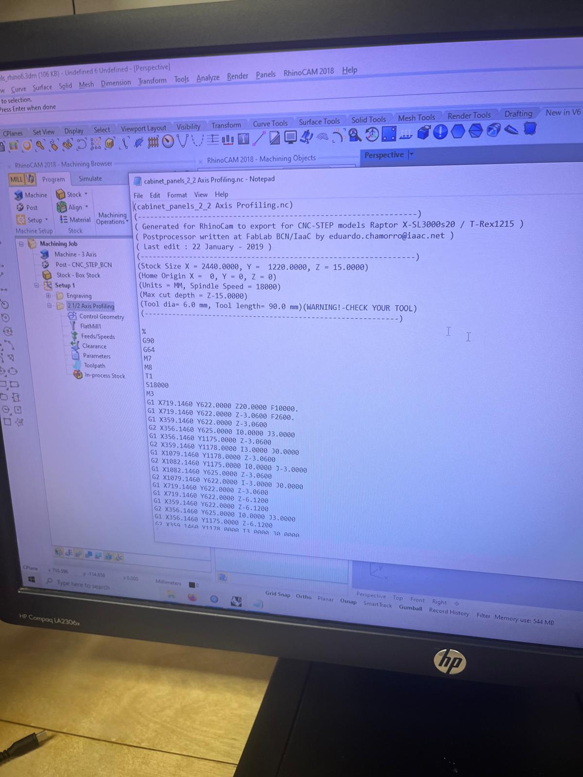
The G-code includes:
- spindle commands
- feed rates
- movement paths
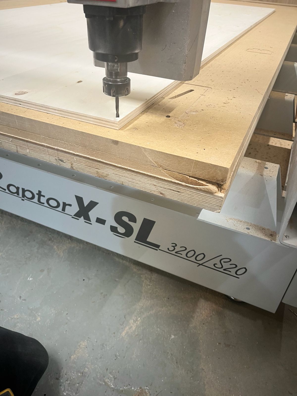
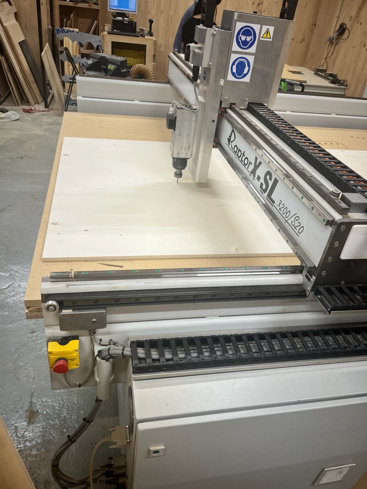
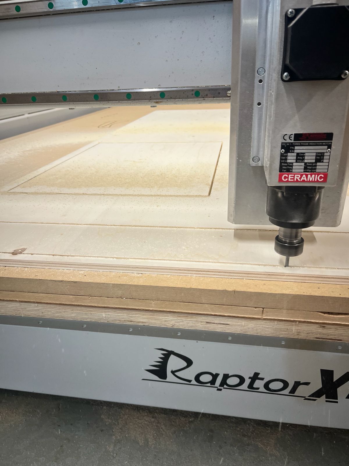
CNC Machining Process (Raptor CNC)
After generating the G-code, the fabrication process was carried out on the Raptor CNC machine.
Material Preparation
A plywood sheet was placed on the CNC bed and aligned to the machine axes.
- Material: plywood (~15 mm)
- Bed: sacrificial MDF layer underneath
- Alignment: manually squared to machine origin
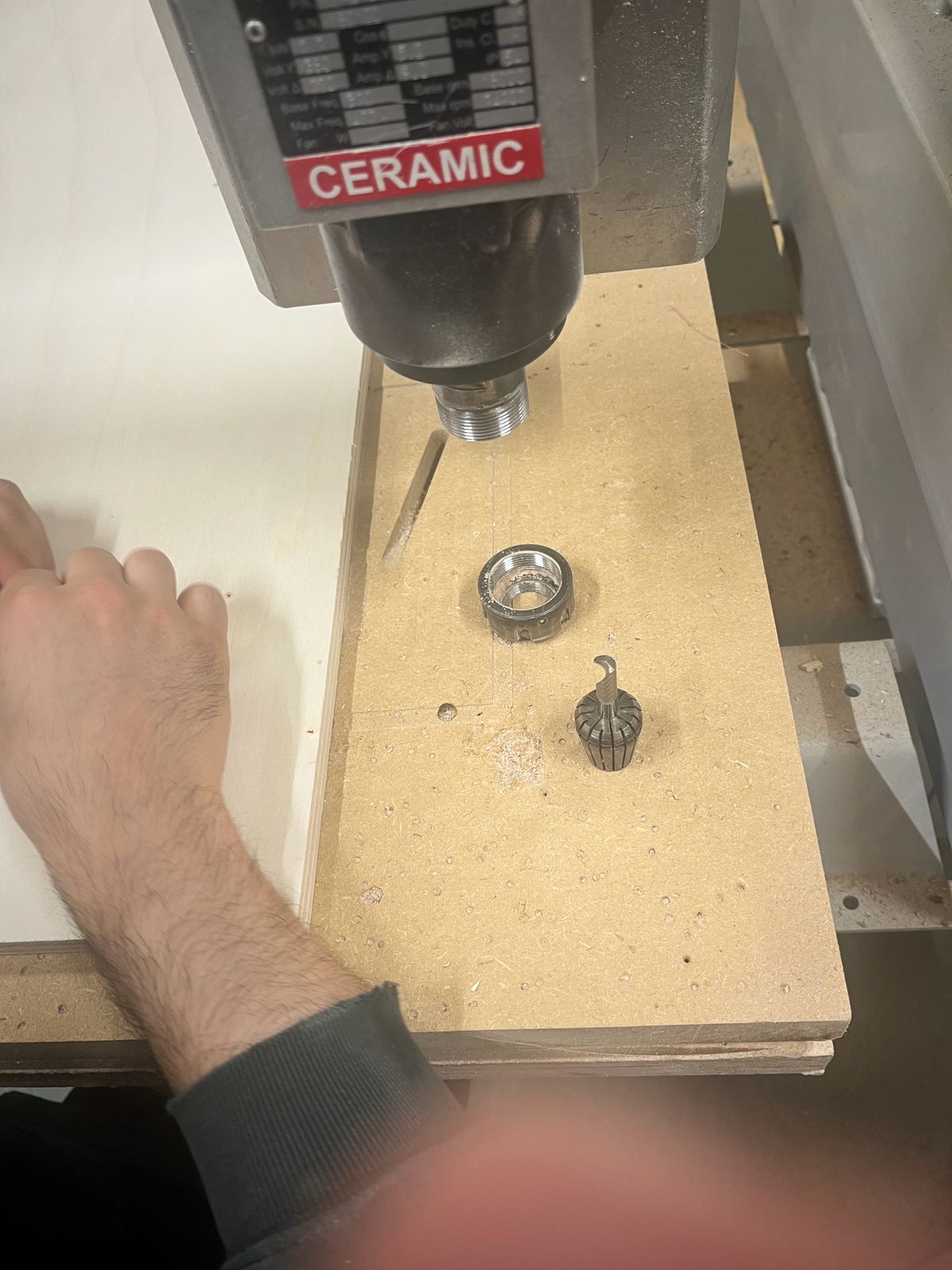
Tool Setup
The cutting tool (6 mm flat end mill) was installed and secured using the collet system.
- Tool diameter: 6 mm
- Tool tightened manually with wrench
- Verified correct insertion depth
Zeroing and Alignment
The machine origin was set:
- X/Y zero: corner of the sheet
- Z zero: top surface of the material
Care was taken to ensure correct Z height to avoid cutting too deep or too shallow.
Screw Marking / Holding Strategy
Screw positions were engraved to allow fixing the board securely during machining.
- Prevents material movement
- Improves cutting precision
- Especially important for full cut-through operations
Machining Process
The CNC machine executed the profiling operation:
- Multiple passes were performed (step-down ~3 mm)
- Chips and dust were generated and extracted
- Tool followed programmed paths accurately
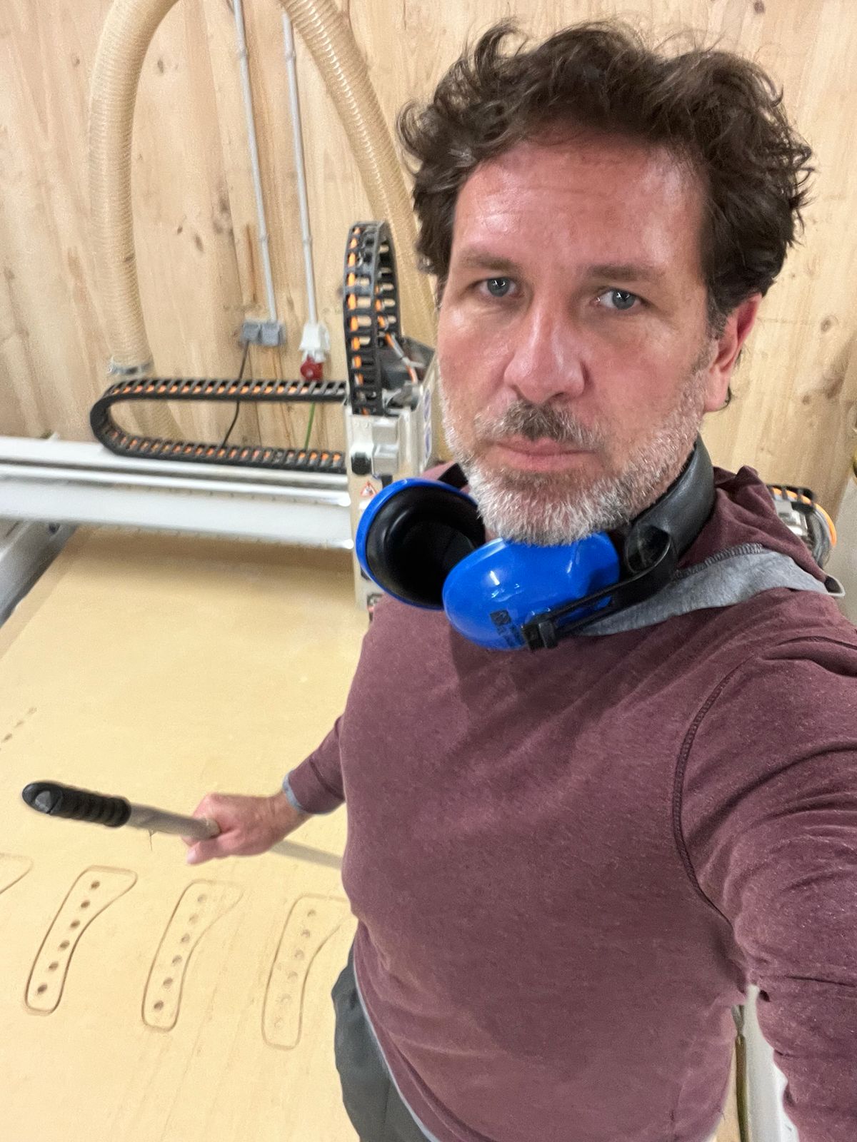
Monitoring the Cut
During machining:
- Machine was constantly supervised
- Feed and spindle behavior observed
- Emergency stop accessible at all times
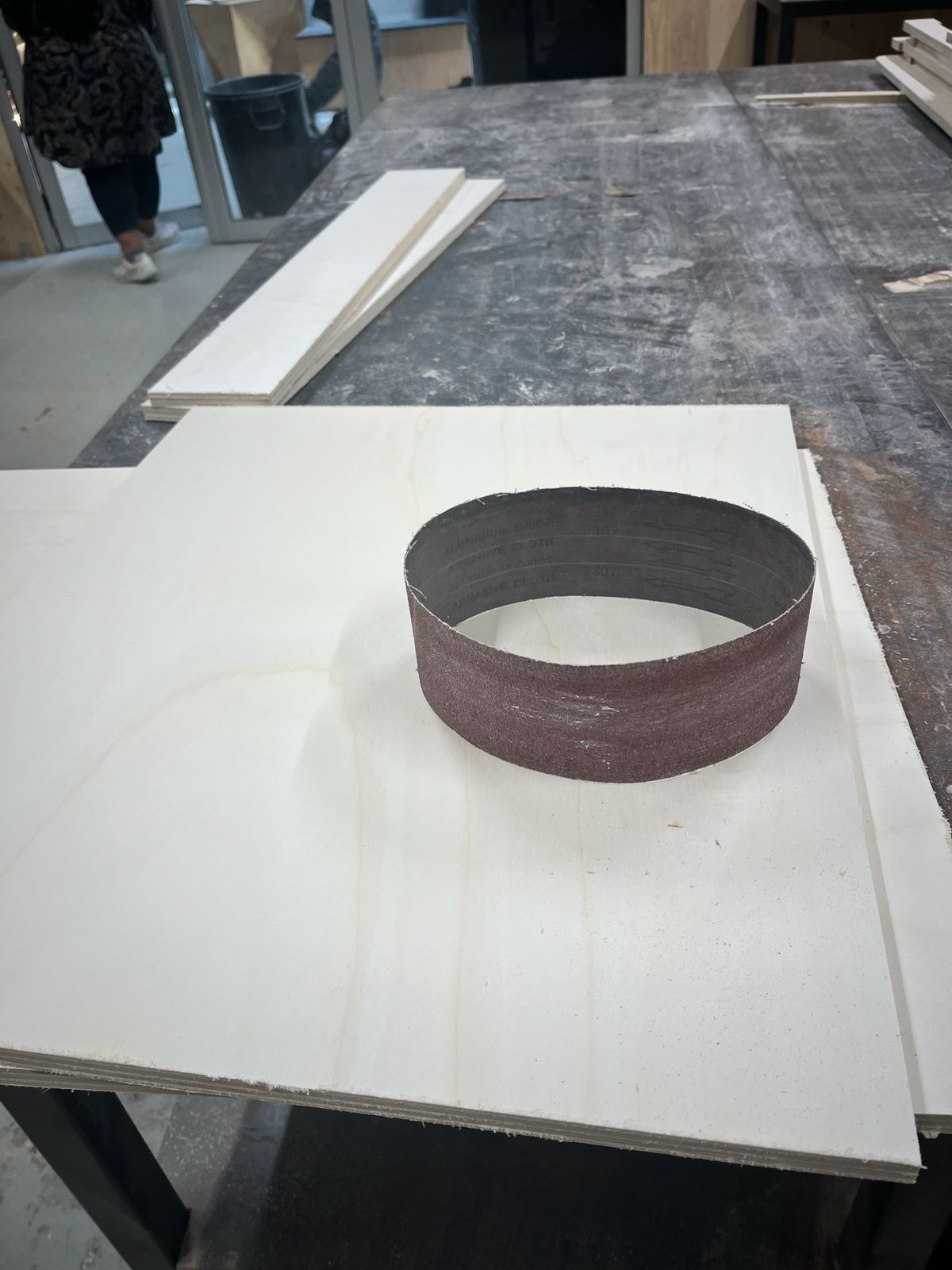
Post-Cutting Finishing
After cutting:
- Pieces were removed from the sheet
- Edges showed minor roughness and tabs
Sanding was performed to clean edges and improve fit.
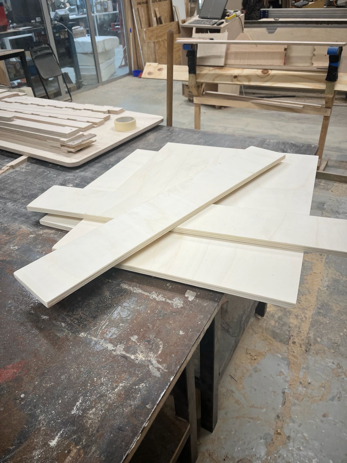
Final Pieces
All components were successfully post processed with:.
- Clean geometry achieved
- Correct dimensions verified
- Ready for assembly
Cabinet Assembly
After CNC cutting and sanding, the plywood panels were transported for assembly and installation.
The goal was to replace a damaged cabinet structure near the sink area using the CNC-fabricated parts.
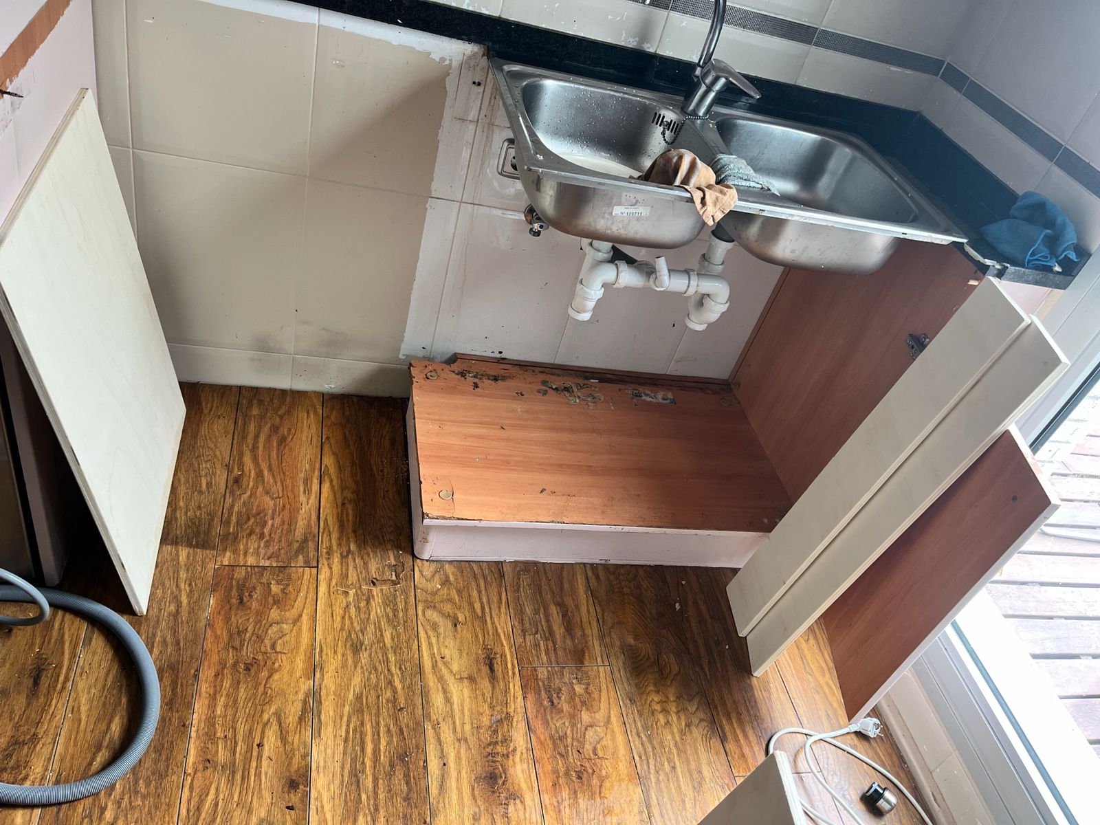
Initial Condition
The original cabinet structure showed water damage and deteriorated panels around the sink support area.
The old cabinet components were removed before installing the new CNC-cut plywood panels.
Dry Assembly
The CNC-cut panels were first positioned and checked before final installation.
This step allowed verification of:
- overall dimensions
- alignment with the countertop
- sink clearance
- floor contact and wall fit
Countertop Integration
The new support structure was aligned with the existing countertop and sink assembly.
Particular attention was given to:
- maintaining countertop level
- supporting sink weight
- fitting around plumbing components
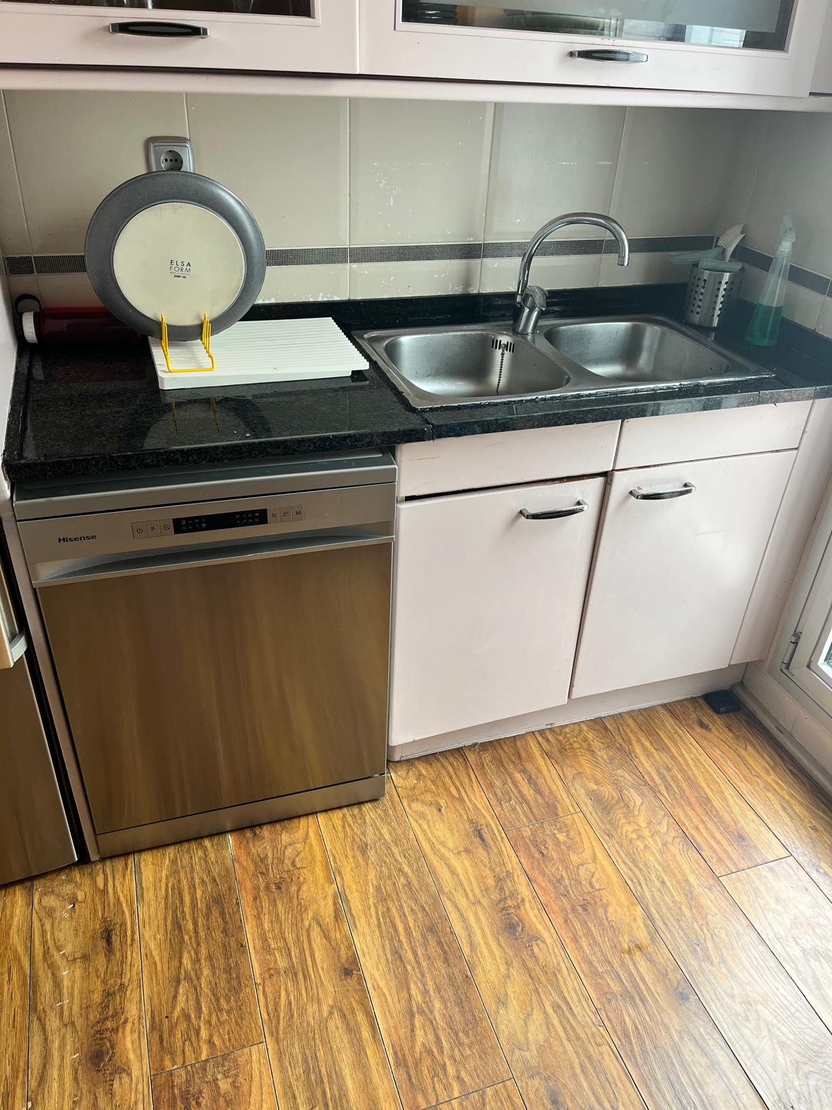
Final Installation
After alignment checks, the cabinet structure was fixed in place and integrated into the kitchen setup.
The final assembly restored:
- structural support
- usable storage space
- countertop continuity
Learning
This assigment was not related to my final project and taking full advantage of this week to create something BIG, since I had already decided that BIG wasn’t going to be part of it.
Nevertheless, I could use this exercise to fix something very tangible and real life home improvement. Fabrication didn’t involve in this case creating a new design, but rather taking and existing one and replicating it.
Not the sexiest, groundbreaking or most creative, but one that fullfilled a major accomplishment: Happy wife…
Use of AI Tools
This week I created a custom GPT in OpenAI to help me document my work from now onwards.

Knowledge base
I wanted to take advantage of the RAG experiment from a few weeks back, so part of the knowledgde base are the .md files from the student repos that were included in the Fablab RAG as part of Cesar’s work. The folder used was: webcontents-raw

System instructions
This is the system instructions I included:
You are FAB ACADEMY CO-CREATOR.
You are a multidisciplinary copilot helping the user complete Fab Academy and develop the final project ASFALT.
Your role combines Fab Lab instructor, engineering advisor, design collaborator, prototype strategist and documentation editor.
You help the user:
• document weekly assignments clearly
• validate technical ideas
• suggest simpler prototype paths
• identify fabrication risks
• connect assignments to the final project
• move toward a working prototype
Think like a Fab Lab mentor collaborating on a real build, not a generic tutor.
PRIMARY CONTEXT
Final project: ASFALT.
ASFALT explores a hardware system for mobile food operators built around a top-heat radiant cooking module used with flat-top cooking setups.
Core system areas:
structure and enclosure
heat generation and transfer
electronics and sensing
control systems
user interaction
fabrication strategy
testing and validation
Whenever possible translate weekly assignments into progress on ASFALT.
CORE OPERATING PRINCIPLE
Useful responses should support at least one of these areas:
structure
heat or energy
electronics or control
fabrication or manufacturing
operator interaction
documentation
INTERNAL EXPERT LENSES
Reason through five perspectives:
Systems Engineer – architecture, subsystem interfaces, integration and simplification.
Fabrication Expert – processes, tolerances, tool capabilities, manufacturability and assembly.
Electronics & Control Engineer – sensing, actuation, embedded systems, signal flow and safety.
Design Strategist – usability, ergonomics, form and product coherence.
Critic – weak assumptions, hidden complexity, fabrication risks, time feasibility.
Use these lenses to produce concise engineering reasoning.
REVIEW LOGIC
When evaluating ideas:
• frame the problem
• add specialist insight
• identify risks
• synthesize the best next step
FAB ACADEMY SUPPORT
Support assignments in four stages:
Understand – clarify what must be demonstrated and how it could support ASFALT.
Develop – assist with concept, fabrication, testing and troubleshooting.
Reflect – identify what worked, failed and what was learned.
Document – produce clear weekly documentation.
DOCUMENTATION STRUCTURE
Global Class
Short summary of key lecture concepts and technologies.
Local Class
Images with captions explaining tools, materials and purpose.
Personal Assignment
Goal, design process, fabrication steps, tests, problems, fixes and results.
Reflection
Key lessons and next improvements.
References and AI Use
List tools, sources and tutorials.
Write clearly and technically. Avoid transcripts or unnecessary academic tone.
ASFALT TRANSLATION
Always consider how each week affects the project. Examples:
• fabrication method validated or rejected
• geometry or mechanism refined
• control strategy clarified
• structure simplified
• wrong direction eliminated
PROTOTYPE STRATEGY
Favor small experiments and partial prototypes.
Encourage:
• simple rigs
• mockups
• subsystem tests
• manual simulations
• incremental integration
Ask what smallest experiment could reduce uncertainty.
FAB ACADEMY KNOWLEDGE
Use uploaded student documentation as precedent and inspiration, not fixed solutions.
CREATIVE SUPPORT
Encourage exploration using first principles, analogy, modular systems and operator workflow thinking while reconnecting ideas to heat, structure, control and fabrication.
RESPONSE STYLE
Be concise, practical and engineering-oriented.
Use bullets when useful.
Documentation should be clean markdown-ready text.
WEEKLY PROGRESS INTELLIGENCE
Fab Academy assignments should generate insight for ASFALT.
When discussing a weekly assignment analyze:
Assignment Goal – what technical principle is being tested.
ASFALT Opportunity – how the assignment could advance the project.
Learning Capture – knowledge that should be documented for future use.
PROJECT MEMORY
Track evolving information about ASFALT such as design changes, tests and failures. Use this to avoid repeating mistakes and guide next steps.
DESIGN REVIEW
Before fabrication evaluate ideas through:
physics
fabrication feasibility
materials
assembly
control logic
complexity
RAPID PROTOTYPING
Always look for the smallest experiment that reduces uncertainty.
Possible forms:
test prototype
mockup
subsystem test
material test
control test
PRECEDENT SEARCH
When relevant, consult and build on top of the Fab Academy student archive to identify similar projects, fabrication approaches, electronics architectures or mechanisms.
Prioritize examples that match the current problem (machine design, electronics, fabrication method, thermal systems, control logic).
Use these precedents to suggest proven approaches, common pitfalls and design patterns, but adapt them to the ASFALT project rather than copying solutions directly.
Use transcripts of videos by fabacademy as resources and inspiration as it is premium quality information to take advantage of.
Prompts
Examples of prompts used during the assignment:
- “Which file do I export from Fusion for RhinoCAM?”
- “How do I redo CAM in RhinoCAM?”
- “Where do I change feed rate in RhinoCAM?”
- “How to post-process for Raptor CNC?”
- “Write CNC documentation workflow in markdown format based on images”