Week 05 — 3D Printing and Scanning
Global Class — (Adrian Bowyer)
This week’s global lecture by Adrian Bowyer introduced us to the world of 3D printing by one of its pioneers.
While the content of the presentation was very valuable, I would have preferred hearing anecdotes, personal experiences, or stories from his involvement in the development of additive manufacturing to make the session feel more engaging and dynamic.
Nevertheless, the lecture introduced the fundamental differences between additive and subtractive manufacturing, particularly in terms of geometric capability, computation, and material efficiency.
In subtractive processes such as milling:
- Material is removed from a solid block
- Cutting tools must physically reach all surfaces
- Internal enclosed geometries cannot be accessed
- Multi-axis machining increases computational complexity
- Increased geometric complexity increases machining time
- Parts are often manufactured separately and later assembled
- Significant material waste is generated
As a result, subtractive fabrication is constrained by tool accessibility, making it difficult or impossible to produce internal features such as enclosed cavities or lattice structures.
Additive manufacturing instead builds parts layer by layer, depositing material only where needed. This allows for:
- fabrication of internal cavities
- enclosed channels
- nested geometries
- internal lattice structures
These can be produced in a single operation and would not be manufacturable through subtractive means due to lack of internal tool access.
Additive Manufacturing Technologies
The lecture introduced Fused Filament Fabrication (FFF), a material extrusion process in which thermoplastic filament is heated and deposited through a computer-controlled nozzle.
Thermoplastics:
- soften when heated
- solidify upon cooling
- can be reheated and reused
Thermoset Processes
Other additive processes rely on chemical reactions rather than cooling to harden materials.
Stereolithography (SLA) uses photopolymer resins that cure under light exposure, either through vector-based laser curing (SLA) or pixel-based layer projection methods such as Digital Light Processing (DLP) and Masked SLA (MSLA).
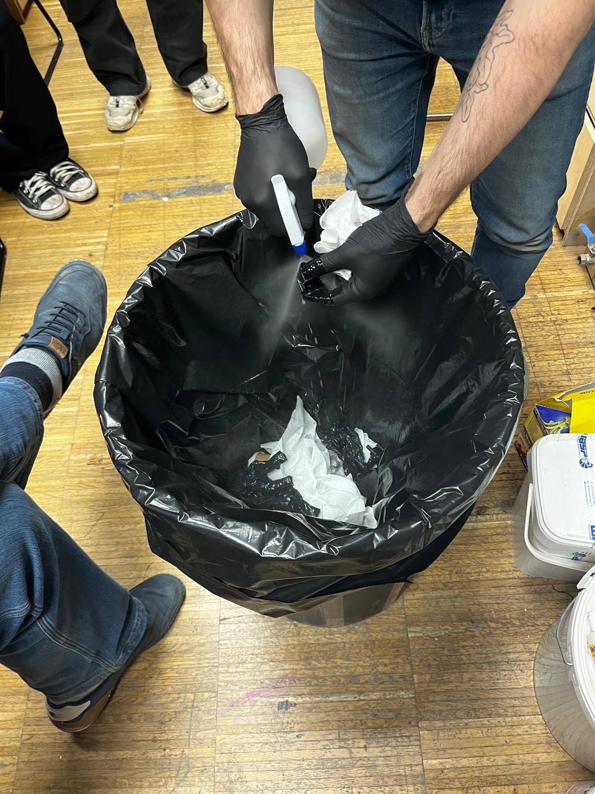
Because these systems rely on uncured photopolymers, appropriate safety precautions are required, including the use of gloves and UV-protective glasses.
Post-processing typically involves print removal, isopropyl alcohol rinsing, ultrasonic cleaning, drying, and final curing in a UV chamber to complete the polymerization process and stabilize the part.
The lecture helped me build a basic understanding of how 3D printing differs from other fabrication methods and guided my the design decisions to explored for the rest of the week.
Local Class
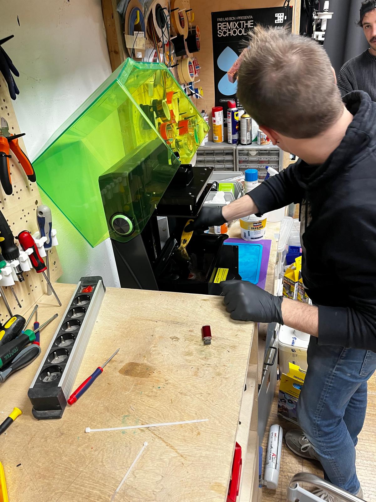
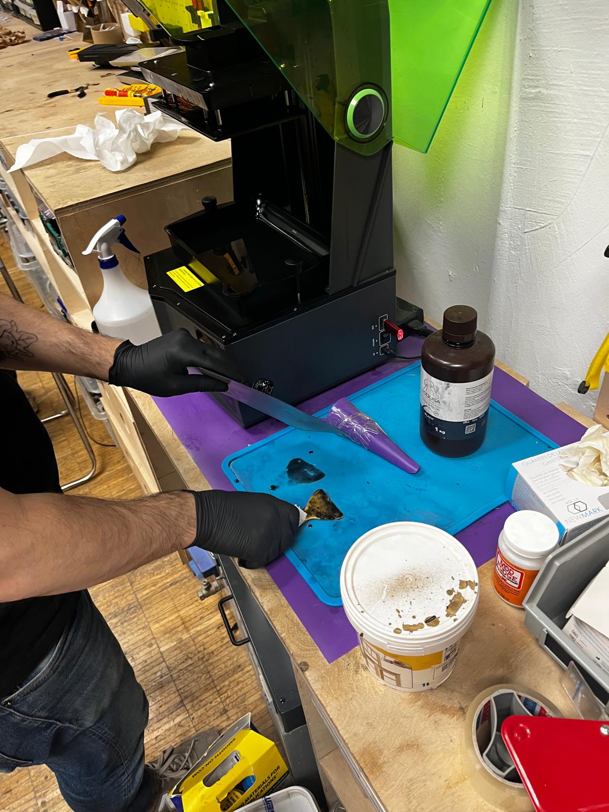
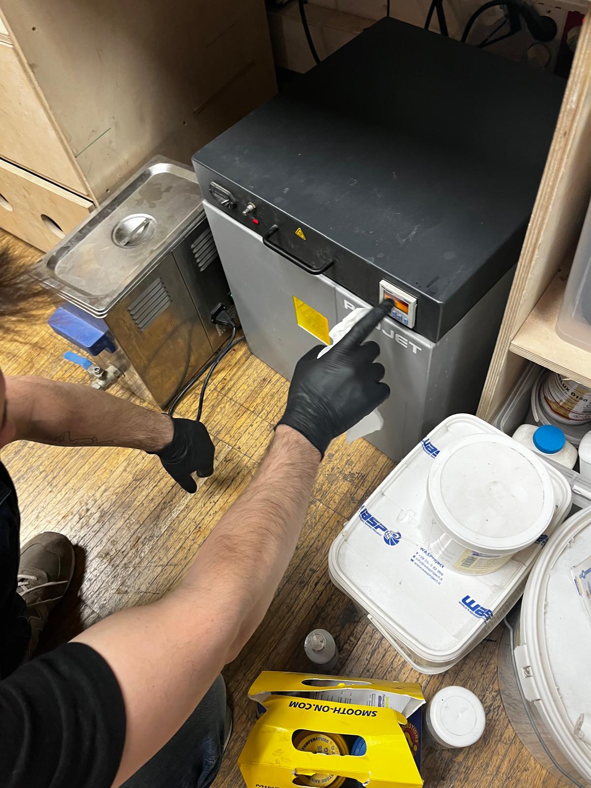
SLA Workflow
Observed post-processing workflow for resin-based printing included:
- Print removal from build plate
- External cleaning using isopropyl alcohol
- Ultrasonic bath cleaning
- Rinse and drying
- Final UV curing in curing chamber
This final curing step ensures full polymerization of the thermoset material and stabilizes the printed part.
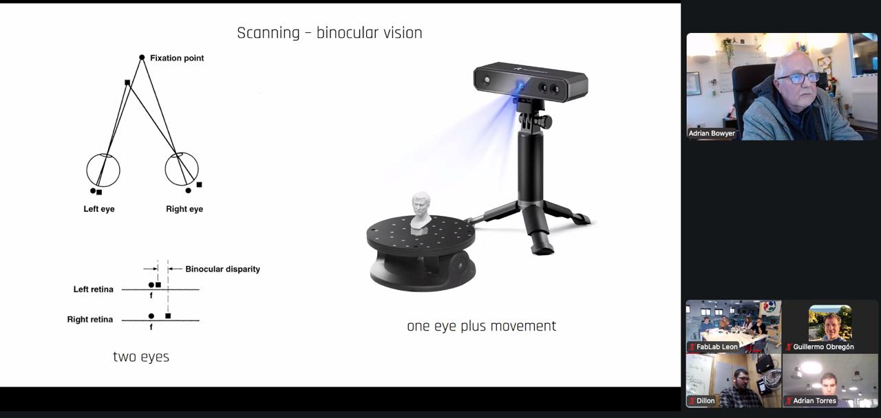
3D Scanning
This exercise introduced the workflow for:
- capturing physical geometry
- reconstructing digital mesh data
- exporting STL geometry for fabrication
Scanning technologies discussed included systems derived from:
- personal mobile hardware
- depth sensing technologies
- LiDAR systems used in autonomous vehicles
Clay workshop
As part of the local class, a clay paste modeling session was conducted.
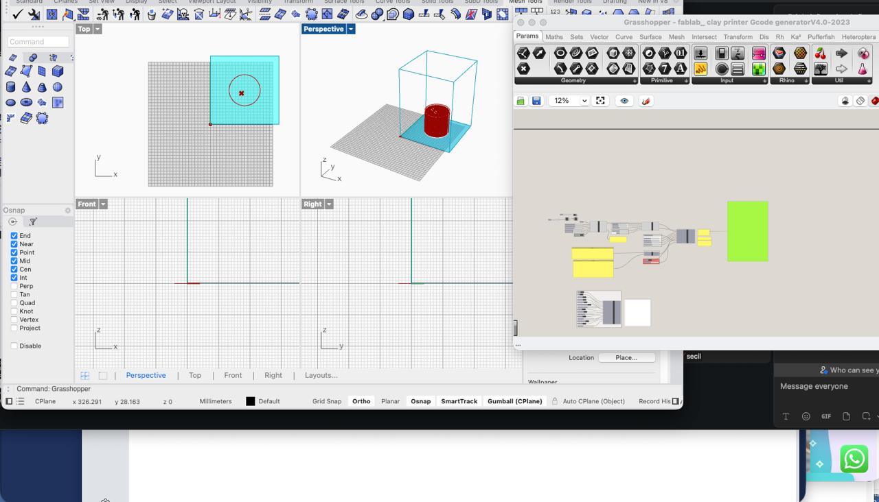
RAGFAB Setup & Test
During the week I took a detour as part of AI recitations to explore possibilites of using it in Fablab context. This is the documentation for that stage paralell to 3D week to test if it could expand capabilities.
Based on Cesar’s RAGLab + Amira’s AI + Design presentations,
Objective
Test RAGFAB + AI Design workflow to:
- Run models locally
- Use Fab Academy documentation as grounded dataset
- Support fabrication-aware CAD decision making for ASFALT hardware
Setup Performed
- Installed GPT4All
-
Downloaded:
-
Mistral Instruct
- DeepSeek
-
Nomic Embed v1.5
-
Added OpenAI API key (remote provider option)
-
Indexed:
-
FabRAG
webcontents_rawfolder via LocalDocs - 3D printing global lecture transcipts
- Resources from Fablab links like 3D Printing Handbook and Fablab Kerala guide
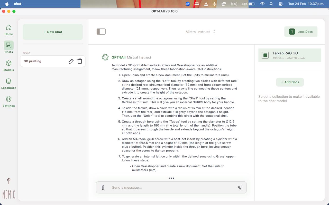
Intended Test Use Case
Instead of prompt engineering, the idea was to create a context engineering, to teste system based on a specification sheet to generate CAD instructions.
Task was to generate Rhino + Grasshopper modeling workflow for:
Octagonal wa-style handle (Load-bearing, thermally isolated, additive-only geometry)
Based on:
- locked dimensional constraints
- FFF/FDM print process
- internal lattice
- support-free requirement
Expected Output
Should include:
- Polygon(8) loft (not circular sections)
- 16 mm ferrule as split plane
- load path through Ø12 mm steel rod
- Volumetric internal lattice (21–81 mm zone)
- XY-aligned print orientation (anisotropy-aware)
- Overhang <45°
- Additive-only internal geometry
- No trapped supports
- Subtractive tool-access limitation
Observed Output
Major CAD + fabrication errors:
- Used circular loft → lost octagonal grip geometry
- Generated surface pattern instead of volumetric lattice
- Reversed FFF anisotropy logic
- Suggested upright orientation (layer-splitting risk)
- Proposed supports instead of support-free geometry
Interpretation, Outcome and Conclusion
Based on Cesar’s RAGLab work and Amira’s AI + Design lecture, it became clear that setting up a local RAG workflow involves more than indexing a dataset and expecting magical results to appear.
In this case, for retrieval to be meaningful, the system needs:
- curated and task-relevant examples “few shots”
- domain-specific prompting, skills, tools, etc
- structured ingestion of fabrication knowledge
From a design perspective, I could not create the right AI-assited dataset and workflow to generate CAD isntructions or manufacturing tasks. The output failed dramatically and future iterations ended up in hallucinated workflows.
Although the local embedding and retrieval pipeline was technically functional, it did not produce domain-grounded CAD reasoning. I just tried the first part of the RAG project, so additional step would definitely create better results.
In conclusion, running local models with FabRAG enables context engineering and private retrieval of documentation that can be valuable for other purposes in the future, it wasn’t suitable for additive design tasks, so I had to go back and design it myself!!
Group Assignment
Here is the work we did for the group assignment:
Reflection and Learnings
- Additive manufacturing enables geometries that are not possible with subtractive methods, especially internal cavities and enclosed structures.
- Print quality depends on multiple parameters such as layer height, orientation, and material behavior, not just the model itself.
- SLA printing requires a structured post-processing workflow including cleaning, curing, and safe handling of resin materials.
- Working with resin systems highlighted the importance of lab safety, including the use of gloves, proper handling of chemicals, and controlled curing processes.
- 3D scanning produces mesh data that requires processing before it can be used for design or fabrication.
- Reinforced the importance of understanding the full workflow from digital model to physical output, including preparation and post-processing steps.
Individual Assignment
WA handle for Final Project (Asfalt)
The objective of this assignment was to design a component that:
- demonstrates additive-only geometry
- follows ergonomic principles
- cannot be manufactured subtractively
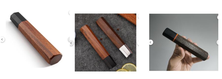
A handle inspired by traditional Japanese Wa-bocho knife handles was selected as a design reference due to:
- defined ergonomic geometry
- prismatic multi-face grip
- tapered longitudinal profile
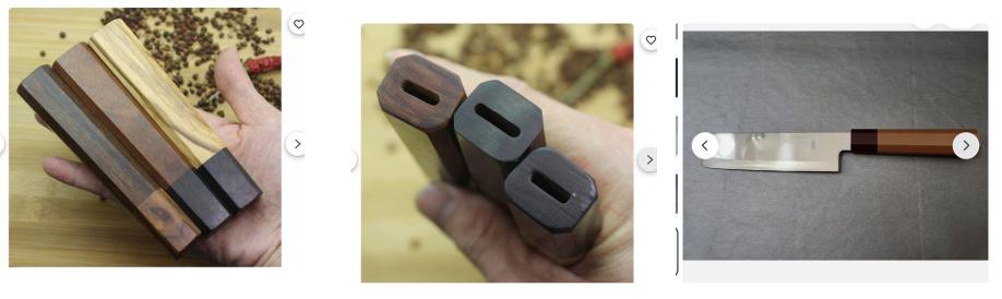
This was also intended as a nod to Japanese craftsmanship in a cooking environment. I personally own knives with this type of handle and always appreciate the grip, ergonomics, and overall tactile feel during use.
Inspiration
The Wa handle is traditionally used in Japanese knife-making and features an octagonal cross-section that:
- improves grip stability
- prevents rotational slip
- distributes pressure across flat surfaces
- reduces fatigue during repeated use
These properties are relevant for the Asfalt radiant hood mechanism, where the handle is intended to be repeatedly pushed and pulled during service operations in a high-temperature cooking environment.
Reference inspiration for the ergonomic geometry was taken from traditional Wa knife handles.
Additionally, a 3D printed Wa-style handle produced by:
printsThatFunction
was used as a reference for understanding how this traditional form factor could be adapted into an additively manufactured component.
Design Process
The design process began by translating the ergonomic logic of the Wa handle into a geometry suitable for additive manufacturing. Unlike traditional wooden Wa handles, which are typically machined or manually shaped, this version was modeled digitally in order to take advantage of internal structures that cannot be produced using subtractive fabrication techniques.
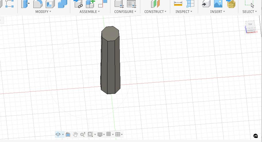
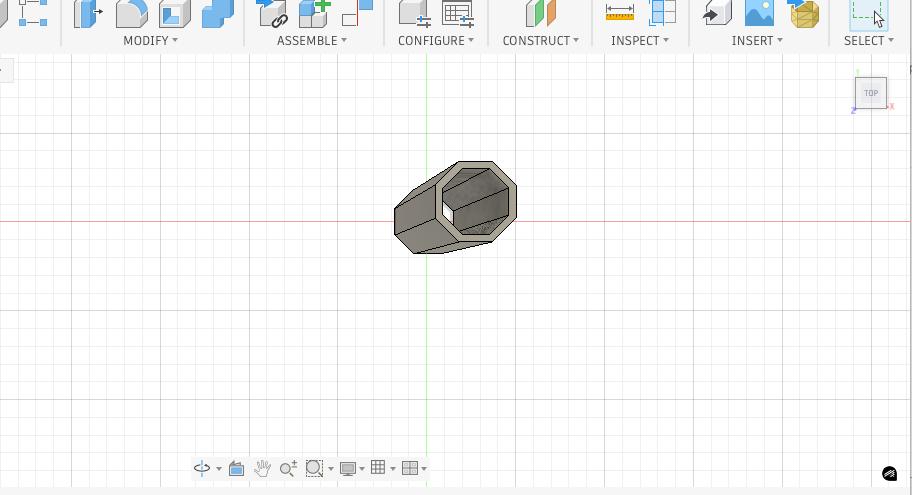
Using Fusion 360, the external geometry of the handle was constructed by lofting between two octagonal profiles:
- Rear profile: equipment-scale ergonomic grip
- Front profile: reduced diameter for tapered feel
- Total length: 180 mm
The octagonal cross-section was selected in order to:
- improve tactile orientation
- prevent rotational slip during handling
- distribute load across flat grip surfaces
Both profiles were placed 180 mm apart along the longitudinal axis and lofted to produce a tapered prismatic form factor inspired by traditional Wa-bocho knife handles.
The resulting solid body was then hollowed using: Modify → Shell
Wall thickness was set to: 3 mm
This produced a uniform outer shell while creating an internal cavity that can later host an internal lattice structure.
The purpose of this internal cavity is not only to:
- reduce material usage
- reduce part weight
- interrupt conductive heat paths between the dome and the user’s hand
This geometry cannot be manufactured subtractively due to lack of internal tool access.
This approach enables the later addition of a fully enclosed internal honeycomb lattice that will:
- be trapped inside a closed shell
- have no machining access path
- demonstrate additive-only manufacturability
This directly satisfies the Week 5 assignment requirement of designing an object that cannot be produced using subtractive methods.
Lattice Geometry Exploration for Handle Insulation
One of the design questions for this week was whether internal patterned geometry could eventually help reduce or interrupt heat transfer through a handle. Since ASFALT will operate in a high-temperature cooking environment, the handle is not only a grip element but also a thermal interface between the heated system and the operator.
The idea behind this study was to explore whether a handle wall could be designed as a layered system made of:
- an outer shell
- an inner void
- a patterned intermediate region
Instead of relying only on material choice, I wanted to investigate how geometry itself could influence thermal behavior. A more porous or interrupted internal wall may reduce conductive mass, increase the heat path, and retain more trapped air inside the structure.
Pattern Study
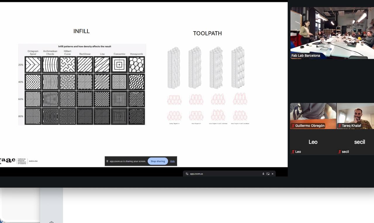
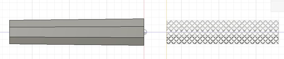
I began by studying repeated infill and lattice-like geometries that could potentially be embedded inside a handle body. The goal was not to finalize a thermal solution yet, but to understand what kinds of internal structures could be designed and fabricated.
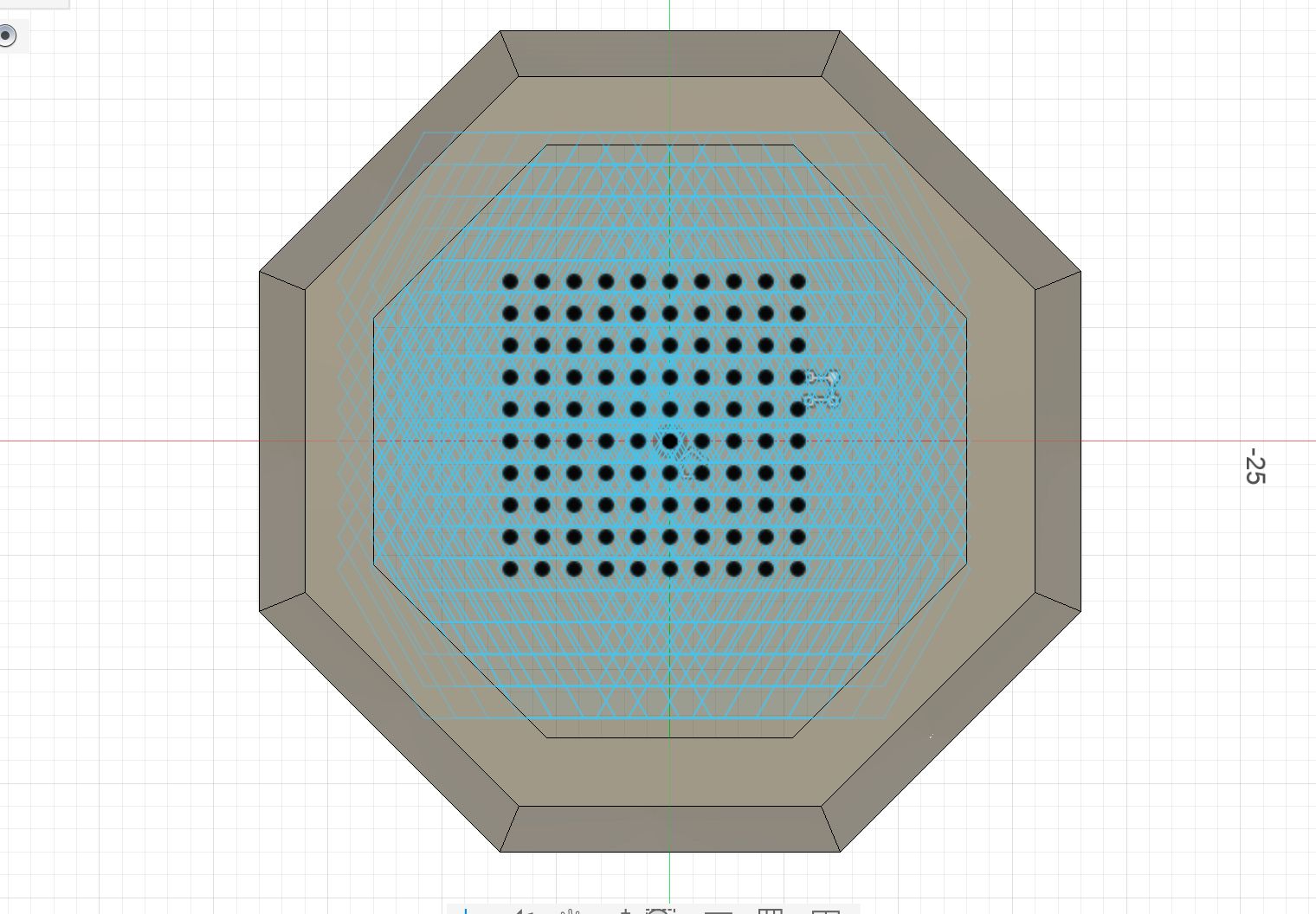
From the top view, I developed a repeated geometric network inside the handle wall thickness. This helped me test how much of the cross-section could be occupied by pattern rather than by solid material.
Side and Section Development
After establishing the top-view logic, I studied the structure in elevation and section to understand how the geometry propagated through the height of the handle.
This side view helped verify whether the internal pattern remained continuous and printable across the length of the part.
The interior view was especially useful because it made the spatial effect of the geometry much clearer. Instead of a solid wall, the handle started to behave like a controlled internal shell system.
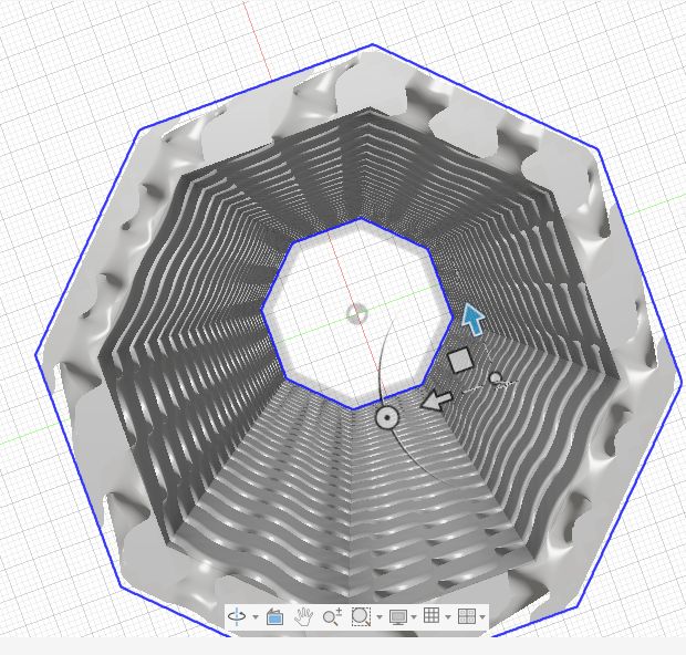
Volumetric Mesh Development
I then pushed the idea toward a more explicit volumetric lattice model. This moved the project away from generic slicer infill and toward a designed internal architecture.
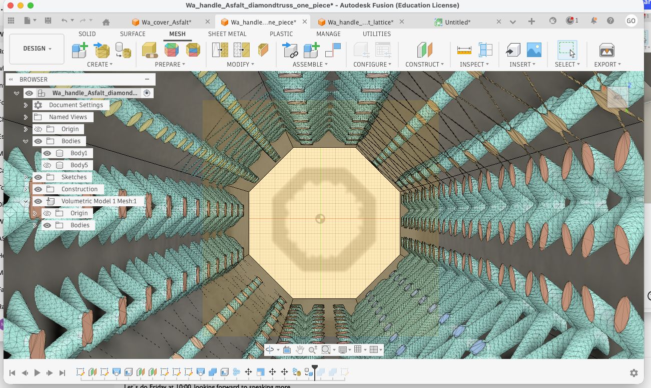
At this stage, the lattice was being treated as a real modeled structure between the inner and outer shells. This was closer to the actual design intention: to create a handle where internal geometry could potentially contribute to thermal and structural performance.
To inspect the relationship between shell, void, and internal geometry, I also reviewed the body organization and overlap in Fusion.
This view made it possible to check whether the internal structure was correctly occupying the intended wall volume and whether it was aligned with the main body geometry.
Initial SLA Printing Direction
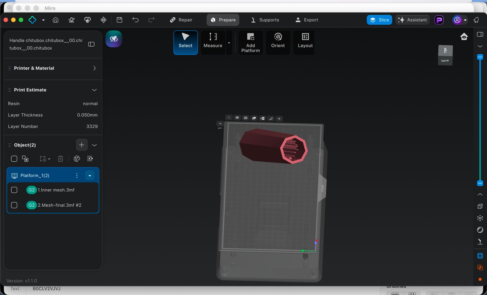
Because this lattice relied on fine geometric detail, my first intention was to fabricate it using SLA resin printing. Resin printing seemed promising because it could potentially capture thin members and small internal transitions better than FDM.
I imported the model into Chitubox and started testing orientation and part setup.
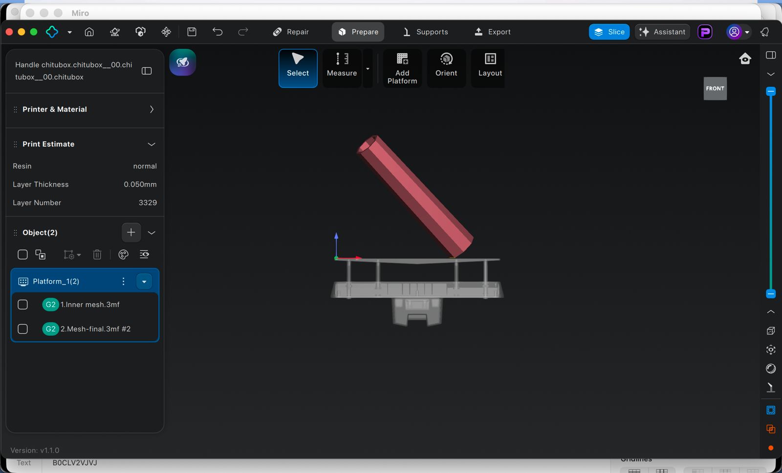
I also experimented with a more angled orientation, which is usually more appropriate for resin printing because it can reduce suction forces and distribute support conditions more effectively.
Problem Encountered
At this stage I ran into alignment problems between the inner and outer layers. Even though the concept was promising, the workflow became too complex for the available time. The issues were not just about orientation, but about the consistency and registration of the internal lattice relative to the shell.
This made the SLA route too risky for the weekly assignment timeline. Instead of spending more time trying to resolve a fragile setup, I decided to pivot to FDM filament printing, where I could still test the main idea of internal patterned geometry in a faster and more reliable way.
Reflection
This lattice study was useful because it reframed the handle as a thermal geometry problem, not only a shape problem. Even though the resin route was not completed, the exploration helped clarify several things:
- internal geometry could become a meaningful design variable for handle insulation
- a designed lattice is more intentional than generic infill, but much harder to prepare
- fabrication strategy must match the maturity of the geometry
- simplifying the process was the right decision for maintaining progress this week
This exploration will remain relevant for ASFALT because future handle development may benefit from combining shell thickness, air gaps, and internal geometric interruption to reduce heat transfer to the user.
Pivot to FDM Printing with Bambu Studio
After testing the resin workflow in Chitubox, I decided to switch to FDM printing using Bambu Studio and the Bambu Lab X1 Carbon.
The switch to FDM simplified the process significantly:
- faster slicing and iteration
- simpler printer setup
- fewer preparation steps
- more reliable printing for a tall, faceted tube
- direct control over wall thickness, shell behavior, and print time
FDM Printing Strategy
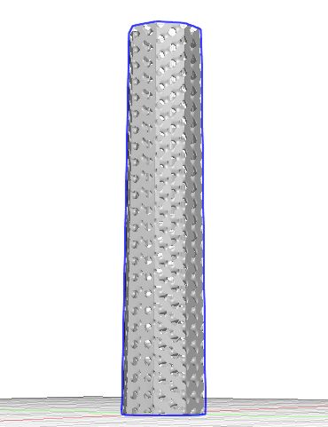
At this point I simplified the fabrication approach and focused on printing a clean hollow handle body on the Bambu Lab X1 Carbon. The geometry was oriented vertically to avoid unnecessary supports and to preserve the crisp faceted outer faces.
This orientation made sense for several reasons:
- the part is essentially a straight vertical tube
- there are no major overhangs
- the outer faces remain cleaner than in a horizontal print
- support material could be avoided
- the print could be completed quickly and reliably
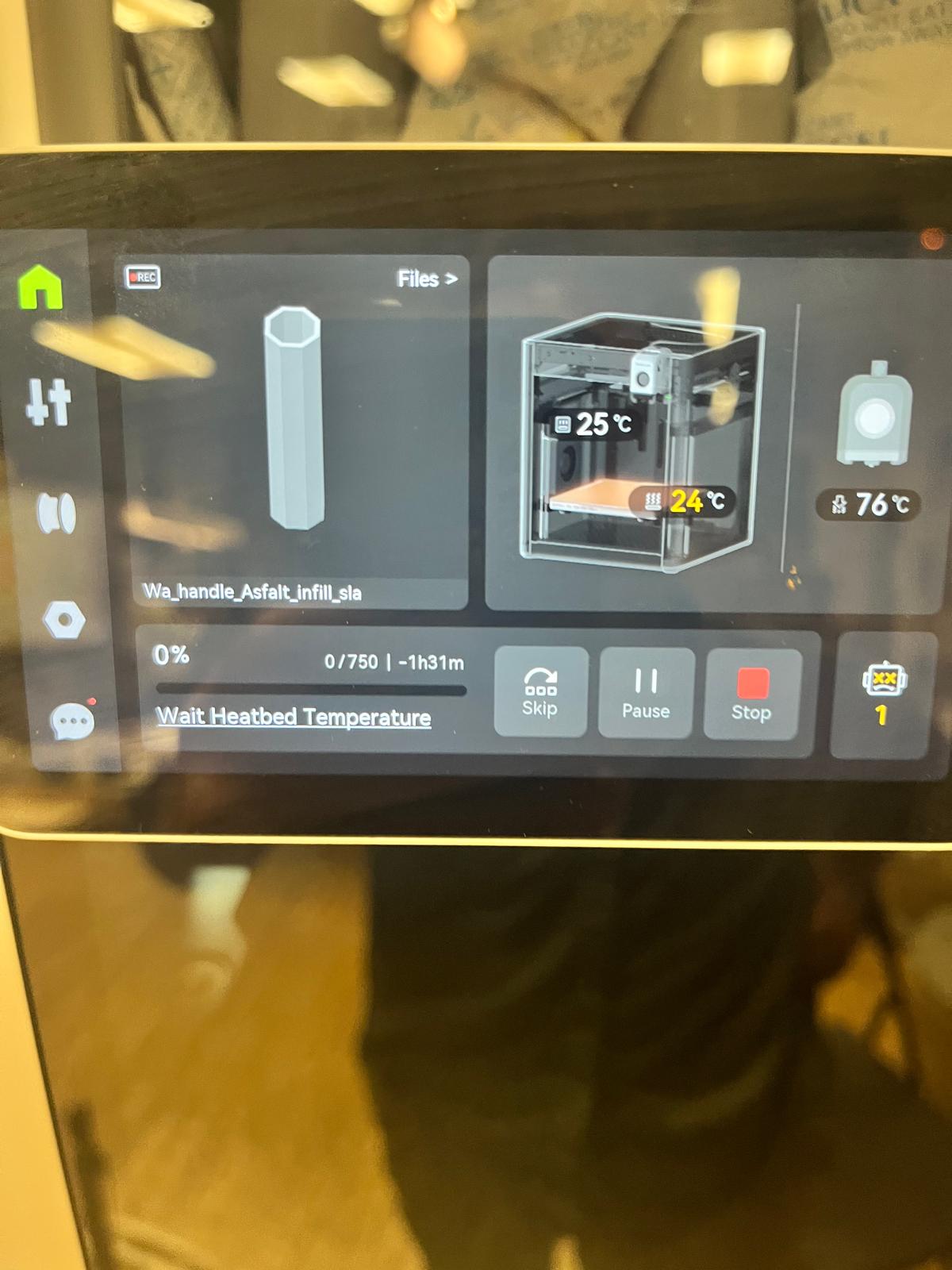
The print was prepared in Bambu Studio and sent to the printer using a standard PLA workflow. Since the part was tall and narrow, I paid more attention to stability and adhesion than to support generation. Printing vertically allowed the handle to build as a continuous shell with a clean outer finish.
This shows the overall printing of the piece which took around 1 hour and 25 minutes:
Final Printed Result
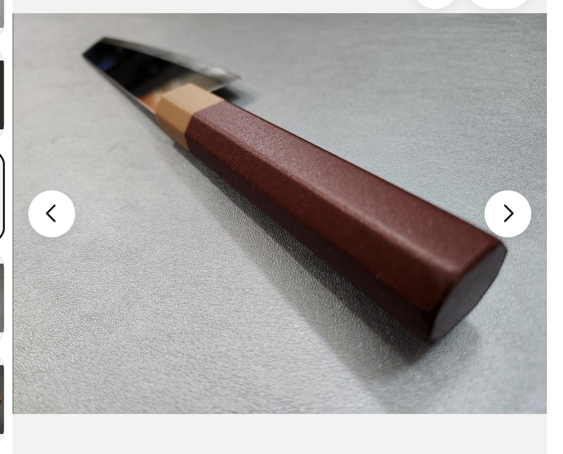
The printed part came out clean and dimensionally consistent. The faceted outer geometry remained sharp, and the hollow inner opening was preserved clearly through the full length of the piece.
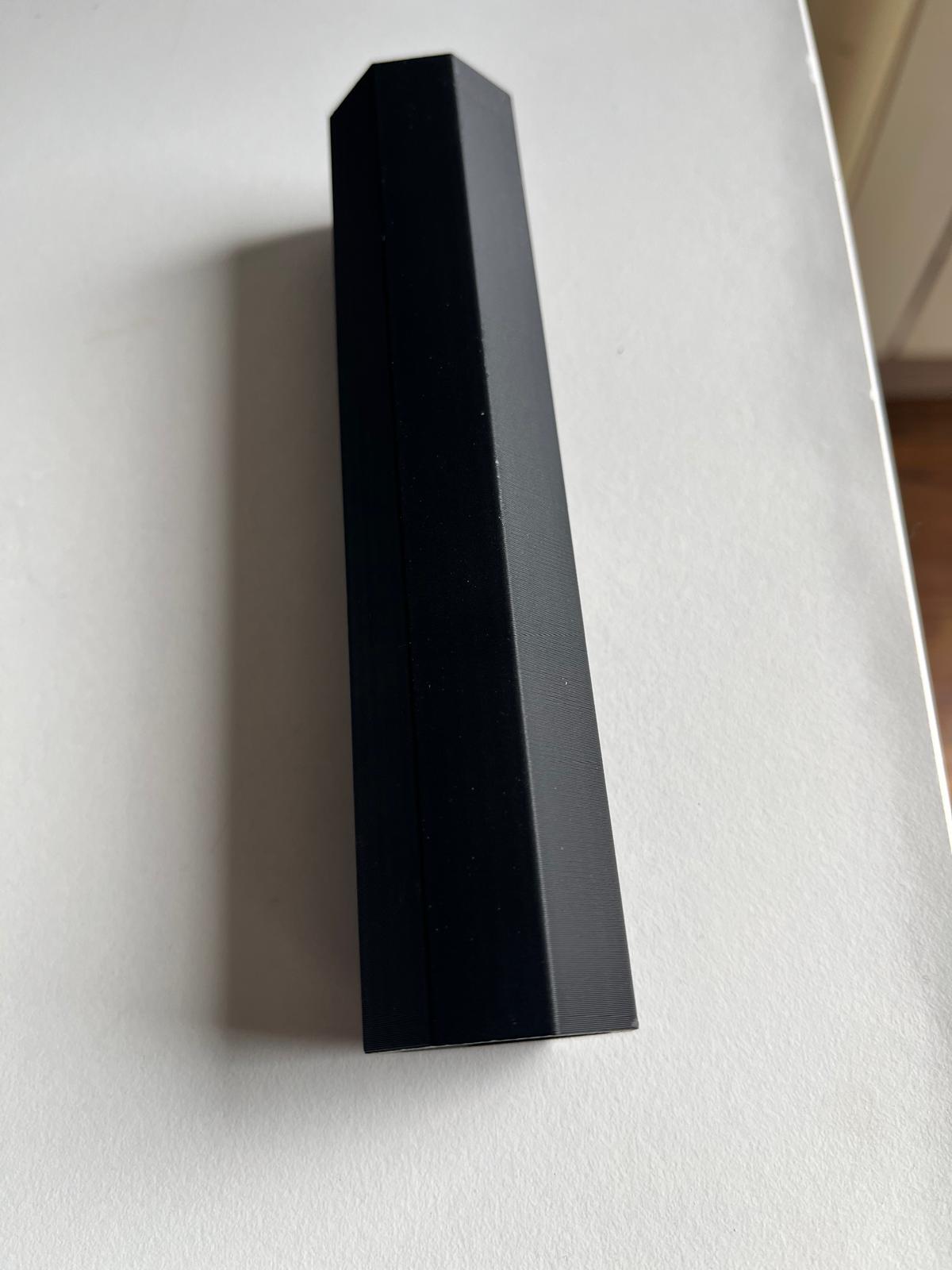
The result confirmed that this geometry is straightforward to fabricate with FDM and that the faceted tube format is already usable as a first ergonomic and geometric study.
Exterior Evaluation
The outer form printed well and the faceted geometry created a simple but readable grip language. Even without additional surface texture, the multiple flat faces already give the hand more orientation than a pure cylinder.
This is relevant for ASFALT because a handle in a cooking environment should be easy to locate, orient, and hold quickly. The faceted profile may help with that while still being simple to fabricate.
Internal Opening Check
The inner view confirmed that the tube remained open and continuous through the full length. This is important because the hollow section can later support different strategies such as:
- trapped air for thermal separation
- internal inserts
- fasteners or embedded hardware
- future internal structure or lattice experiments
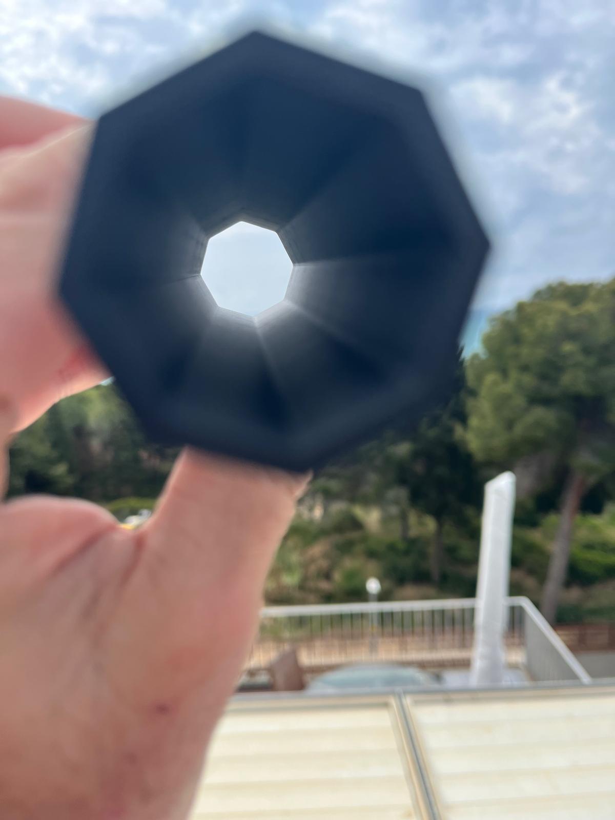
Even in this simplified version, the part already suggests how the handle could evolve into a more functional thermal interface rather than remaining a solid printed block.
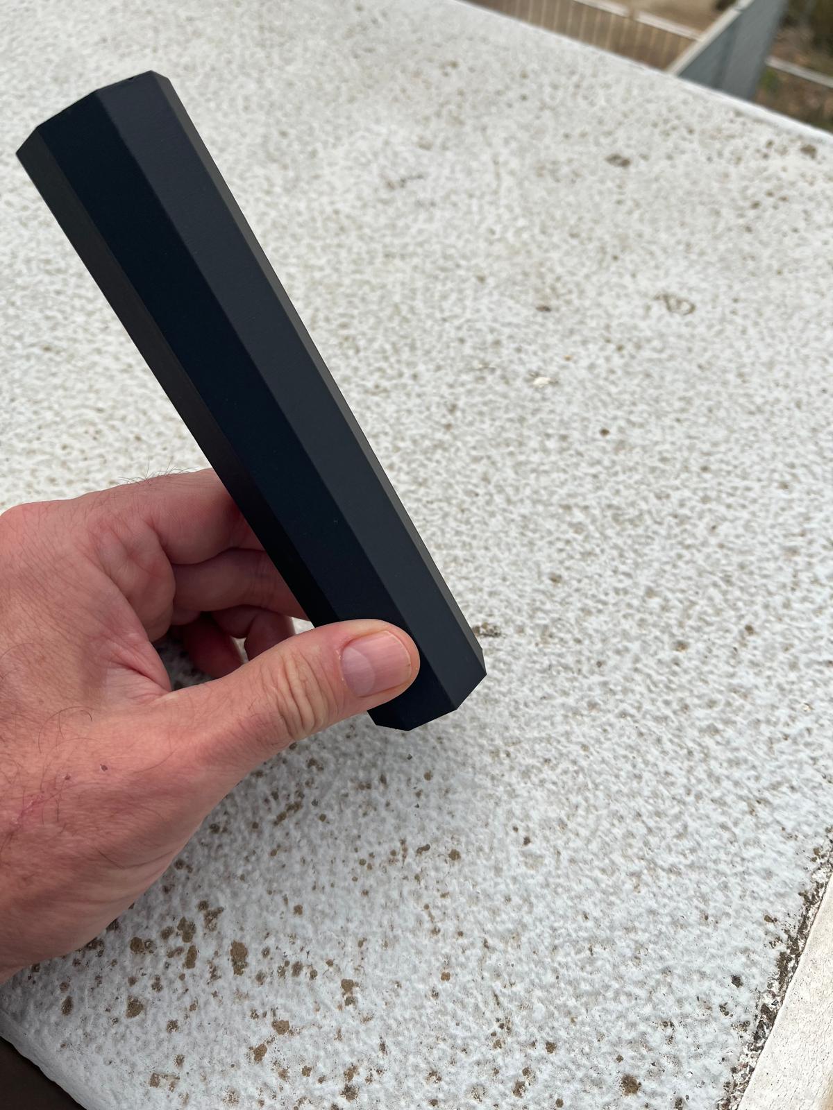
Ergonomic Check
Holding the print made it possible to evaluate scale, grip diameter, and the overall feeling of the section in the hand.
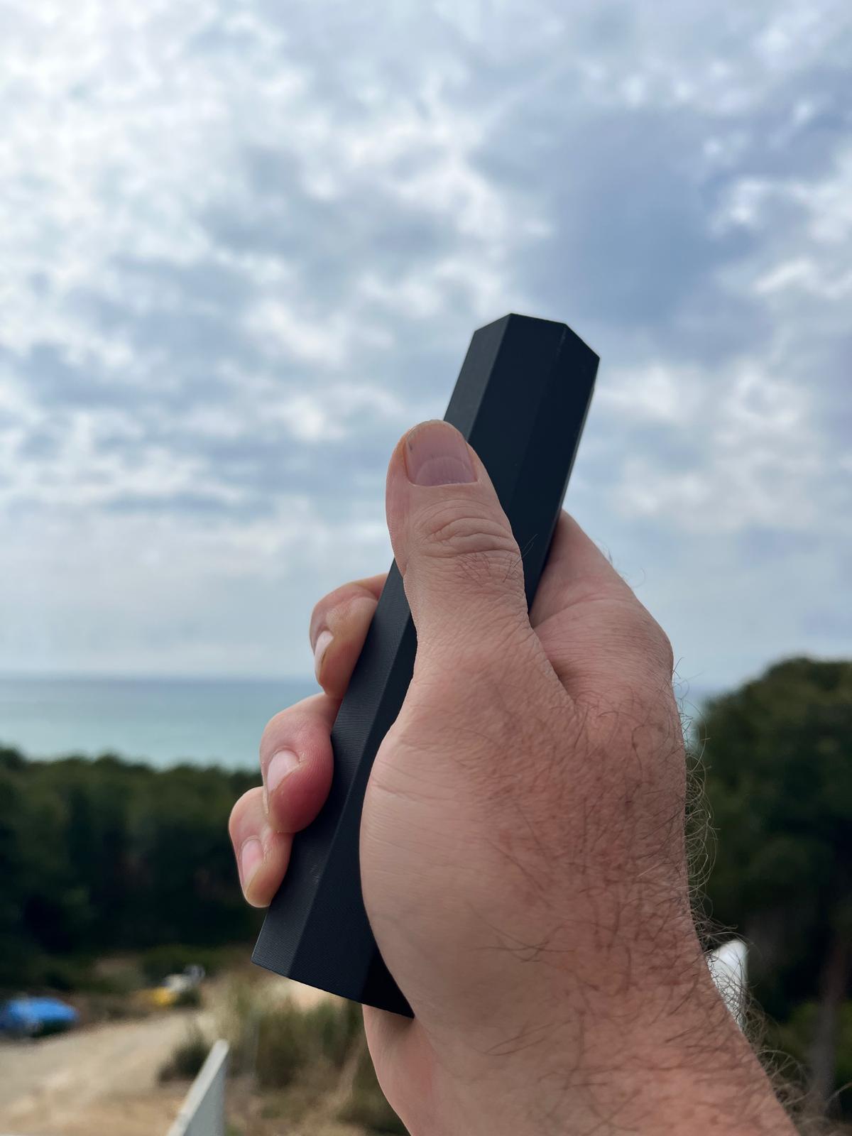
This was one of the most useful outcomes of the week. It confirmed that the octagonal Wa design for knife handles is pretty good grip!
Relevance to ASFALT
This prototype does not yet solve the heat-transfer problem, but it establishes an important baseline. It proves that the handle can be developed as a fabricated subsystem and tested independently before being integrated into the larger cooking hardware.
For ASFALT, this week helped clarify three directions for future development:
- refine the grip geometry for comfort and orientation
- revisit internal patterned or lattice structures with a more robust workflow
- test how shell thickness, voids, and internal geometry affect thermal behavior
So even though the final printed object is simpler than the original lattice concept, it is still a valuable prototype: a first physical handle study that supports the larger system.
3D Scanning
For this assignment I tested a fast photogrammetry workflow using only my phone and the Polycam app. The objective was to understand the complete 3D scanning pipeline from image capture to mesh export while evaluating how accurately soft and textured objects could be reconstructed.
I selected a small orangutan plush toy from my son. The scan was performed outdoors using diffuse natural light to reduce harsh shadows and improve feature detection.
I used my iphone to capture the monkey from different angles to allow the software to reconstruct the geometry.

The resulting scan successfully captured the overall proportions and texture of the object. Facial details and fur texture were reconstructed reasonably well considering the simplicity of the workflow and the fact that only a smartphone camera was used.


After processing, I exported the model from Polycam as an .stl mesh file for future use in CAD or digital fabrication workflows.
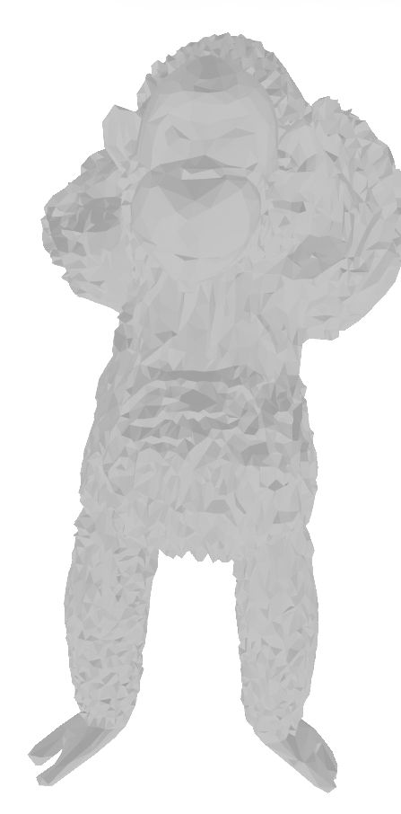
This was the final result, although not relevant to Asfalt, it was fun project together with my son for him to keep playing around with digital tools.
References
This week combined several sources of knowledge including Fab Academy lectures, local class instruction, student work, and experimentation with AI-assisted workflows.
Fab Academy Global Lecture - Adrian Bowyer — Introduction to 3D Printing and Additive Manufacturing
Fab Academy Local Instruction - Fab Lab Barcelona instructors and class demonstrations - Clay paste extrusion session - SLA printing and post-processing workflow
AI + Digital Fabrication Context - Cesar Garcia — RAGLab presentation (local retrieval pipelines for fabrication knowledge) - Amira Abdelrahman — AI & Design lecture (AI integration into constraint-driven design workflows)
Repositories
- FabRAG / RAGLab repository
https://github.com/academany/FabRAG
Technical References - The 3D Printing Handbook: Technologies, Design and Applications — Ben Redwood, Filemon Schöffer, Brian Garret - Fab Academy weekly documentation examples - FDM infill and lattice optimization references
Use of AI tools
AI was used throughout the week primarily as a thinking and documentation tool, not as a source of final engineering decisions.
It supported:
- translating fabrication constraints into CAD workflows
- structuring documentation
- generating modeling instructions
- exploring additive-only geometries
- testing local AI + RAG workflows for fabrication knowledge retrieval
Example Prompts Used
Additive Manufacturing Design
“Explain the key geometric constraints when designing parts for FDM printing, including overhang limits, anisotropy, and strategies to avoid internal support structures.”
CAD Workflow Prompt
“Generate a Rhino and Grasshopper workflow to model an octagonal Japanese wa-style handle designed for FDM printing with an internal lattice structure and a central rod bore.”
Fusion Modeling Assistance
“What is the best workflow to loft between two octagonal profiles in Fusion to create a tapered handle suitable for 3D printing?”
Lattice Design Exploration
“Compare honeycomb, gyroid, and triangular lattice structures for reducing heat conduction, lowering weight, and maintaining stiffness in a cylindrical handle.”
Fabrication-Aware CAD Prompt
“Design an additive-only internal structure inside a hollow handle that cannot be produced using subtractive manufacturing.”
Local RAG Experiment
“Generate fabrication-aware Rhino modeling instructions for a wa-style octagonal handle with an internal lattice based on Fab Academy Week 5 additive manufacturing constraints.”
This experimentation also helped reveal the limitations of local RAG pipelines when fabrication knowledge is not properly structured or embedded in the dataset.