Week 4
Embedded Programming
Week Outline
- Monday: Recitation on Microcontroller Programming.
- Wednesday: Global Class on Embedded Programming.
- Thursday: Local Classes on Digital Electronics, Arduino C on TinkerCAD, and Micro Python on Arduino IDE with Barduino.
- Friday: I simulated my "Hello World" Morse Code program on TinkerCAD.
- Monday: I successfully ran my "Hello World" Morse Code program on my Barduino. Local Class on MCU Families.
- Tuesday: I caught up with my documentation.
- Wednesday: Global Review.
Global Class
This week, Neil introduced us to the topic of embedded programming by discussing the different architectures, languages, and components of programming boards. He talked about memory, peripherals, and word size for processing. He mentioned the different processor families that we will be focusing on and talked about specific boards we will most likely used. He shared some vendors through which we can acquire components. He emphasized on the workflow for choosing components, buyers, and packages for boards. After covering the physical side of things, he did a deep dive into the programming languages of C and Python and how we will use them to program boards.
Local Classes
Basic Electronics
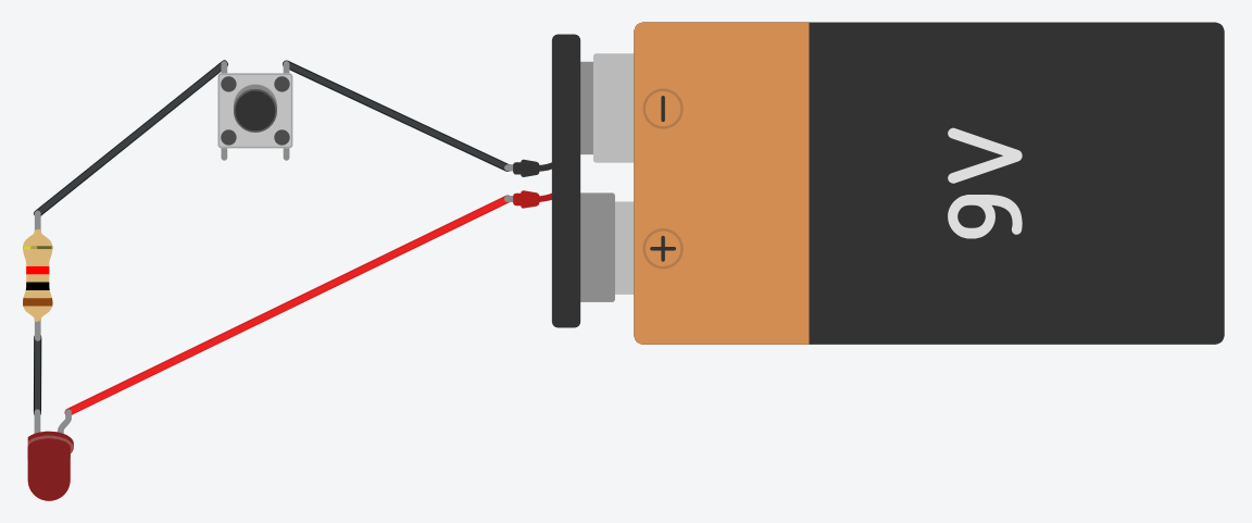
Daniel started us off with an introduction to electronics. He started by explaining how binary works. Then he elaborated on analog and digital inputs and outputs. Then he explained logic levels. Finally he explained the basic concepts of electric circuits and their components. He used TinkerCAD to better help us understand how electric circuits work. Below is an image of the basic circuit with an LED and button that he did:
Arduino C on TinkerCAD
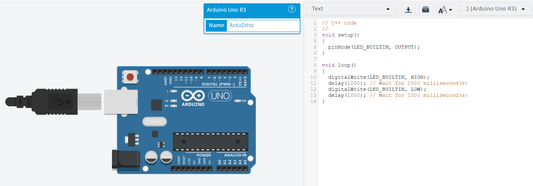
Then, we finally got to the programming part! We used an Arduino Uno R3 component to simulate on TinkerCAD.
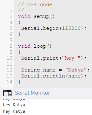
We started with basic programs running only on the code. The first exercise we did consisted of creating a program that printed our name with the following code:
void setup()

{

  Serial.begin(115200);

}


void loop ()

{

  Serial.print("hey ");


  String name = "Katya";

  Serial.println(name);

}
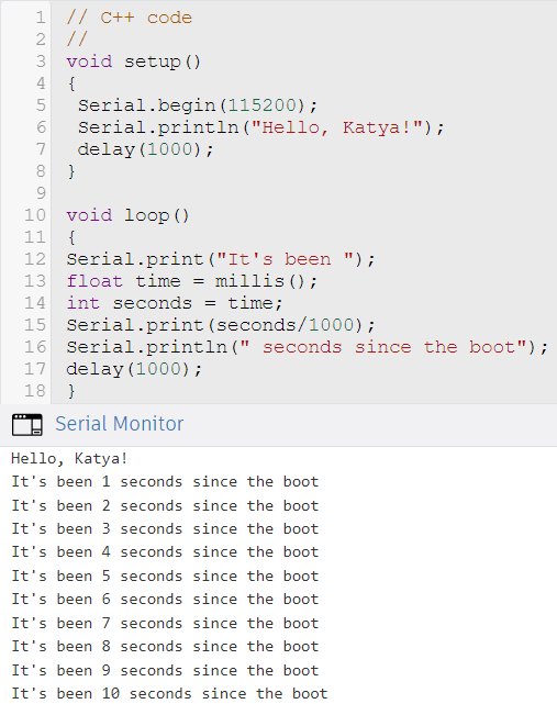
The next exercise consisted of adding upon the program by also having it tell us how much time had passed since the boot. So we used the following code:
void setup ()

{

  Serial.begin(115200);

  Serial.println("Hello, Katya!");

  delay(1000);

}


void loop()

{

  Serial.print("it's been ");

  float time = millis();

  int seconds = time;

  Serial.print(seconds/1000);

  Serial.println(" seconds since the boot");

  delay(1000);

}
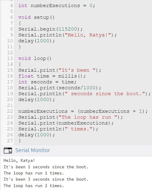
The next exercise consisted of adding upon the program by also having it tell us how many times the loop had run. So we used the following code:
int numberExecutions = 0;


void setup ()

{

  Serial.begin(115200);

  Serial.println("Hello, Katya!");

  delay(1000);

}


void loop()

{

  Serial.print("it's been ");

  float time = millis();

  int seconds = time;

  Serial.print(seconds/1000);

  Serial.println(" seconds since the boot");

  delay(1000);


  numberExecutions = (numberExecutions + 1)

  Serial.print("The loop has run ");

  Serial.print(numberExecutions);

  Serial.println(" times.");

  delay(1000);

}
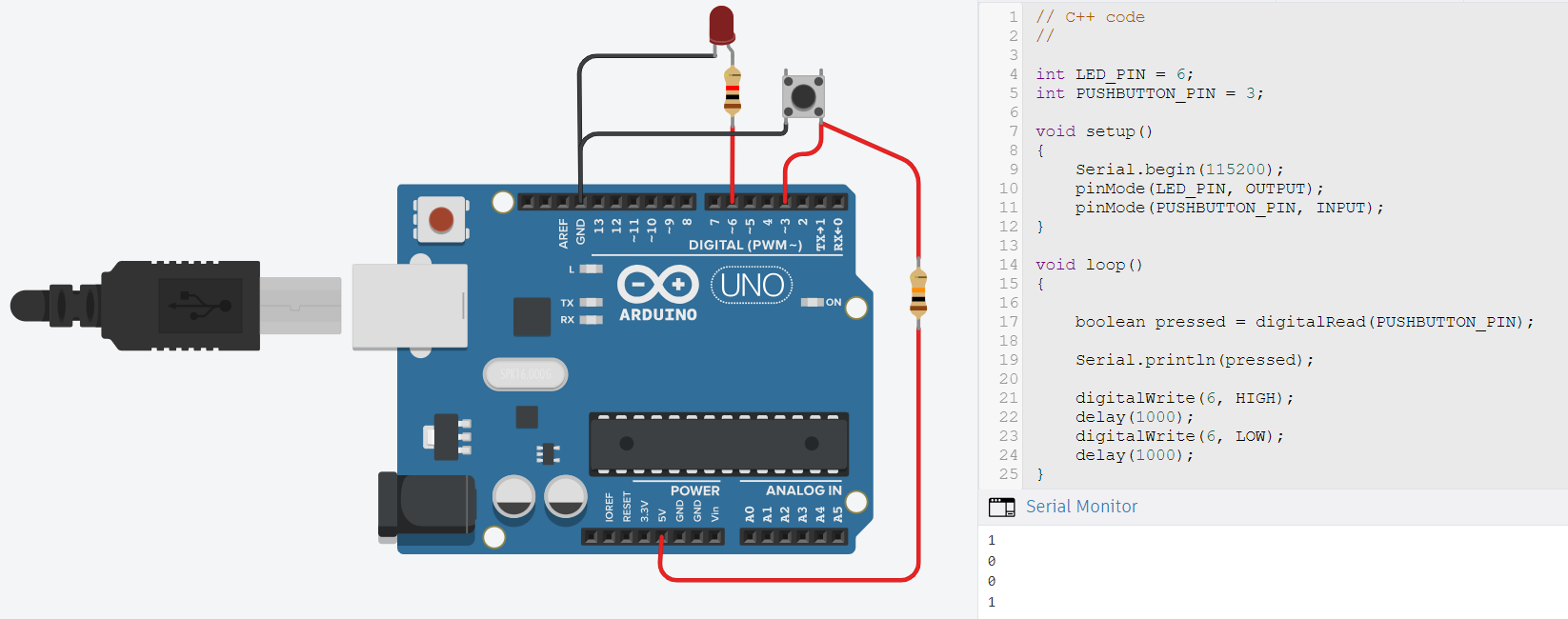
Then, we combined our recently acquired knowledge of programming with electronics, to produce a program that would read and print the logic level of an LED when we pushed a button. We created the electric circuit below and used the following code:
int LED_PIN = 6;

int PUSHBUTTON_PIN = 3;


void setup ()

{

  Serial.begin(115200);

  pinMode(LED_PIN, OUTPUT);

  pinMode(PUSHBUTTON_PIN, INPUT);

}


void loop()

{

  boolean pressed = digitalRead(PUSHBUTTON_PIN);


  Serial.println(pressed);


  digitalWrite(6, HIGH);

  delay(1000);

  digitalWrite(6, LOW);

  delay(1000);

}
Micro Python on Arduino IDE with Barduino
Setting Up Arduino IDE for Barduino Controller
- Downloaded the Arduino IDE.
- Connected the board to the computer.
- Installed the boards needed for the ESP 32 and the SAMD11 by going to File > Preferences > Additional Board Manager URLs and pasting the following lines in the "Additional Boards Manager URLs" section:
https://dl.espressif.com/dl/package_esp32_index.json
https://raw.githubusercontent.com/qbolsee/ArduinoCore-fab-sam/master/json/package_Fab_SAM_index.json
and then installing "ESP32" on the boards manager - Made sure the computer could talk to the board by:
- Selecting Tools > Board > ESP32 > ESP32S3 Dev Module.
- Selecting Tools > Port > COM 3 (ESP32 Family Device).
- Selecting Tools > USB CDC On Boot > Enabled.
Now we can send programs to the board simply by clicking the Upload button on the upper left corner of the screen.
MCU Families
Josep introduced us to the Xiao, RP2040, ESP32, SAMD, and ATTiny microcontrollers. He explained their basic architecture and how they work. Then he showed us how to program an ATTiny 412 and a SAM D11C.
For programming the ATtiny 412 with the Arduino IDE through the UPDI D11C programmer Josep followed these steps:
- Installed the board needed by going to File > Preferences > Additional Board Manager URLs and pasting the following line in the "Additional Boards Manager URLs" section:
https://descartes.net/package_drazzy.com_index.json
and then installing "megaTinyCore by Spence Konde" on the boards manager. - Connected the ATtiny board to a power supply.
- Connected the programmer into the ATtiny.
- Connected the programmer to the computer.
- Burned the bootloader.
- Verified.
- Uploaded a trial blink program into the ATtiny through the programmer.
For programming the SAM D11C with the Arduino IDE through the SWD D11C programmer, Josep followed these steps:
- Installed the board needed by going to File > Preferences > Additional Board Manager URLs and pasting the following line in the "Additional Boards Manager URLs" section:
https://raw.githubusercontent.com/qbolsee/ArduinoCore-fab-sam/master/json/package_Fab_SAM_index.json
and then installing "fab SAM core for Arduino" on the boards manager. - Connected the SAM D11C to a power supply.
- Connected the programmer into the SAM D.
- Connected the programmer to the computer.
- Selected the programmer.
- Burned the bootloader.
- Uploaded a trial blink program into the SAMD through the programmer.
Assignments
1. As a group, demonstrate and compare the toolchains and development workflows for available embedded architectures
The documentation of the work we did can be found here.
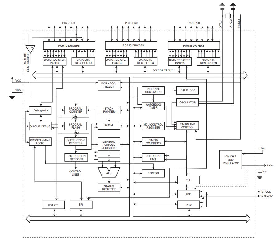
2. Browse through the datasheet for your microcontroller.
For simulating, we were programming using the Arduino UNO R3 on TinkerCAD. The actual board uses a ATMega16U2 microcontroller. It is a high-performance/low-power, 8-bit AVR microcontroller with 16K Bytes of ISP flash. It has an advanced RISC architecture and a USB 2.0 full-speed device module. It has 24 pins. Its operating voltages are between 2.7V and 5.5V.
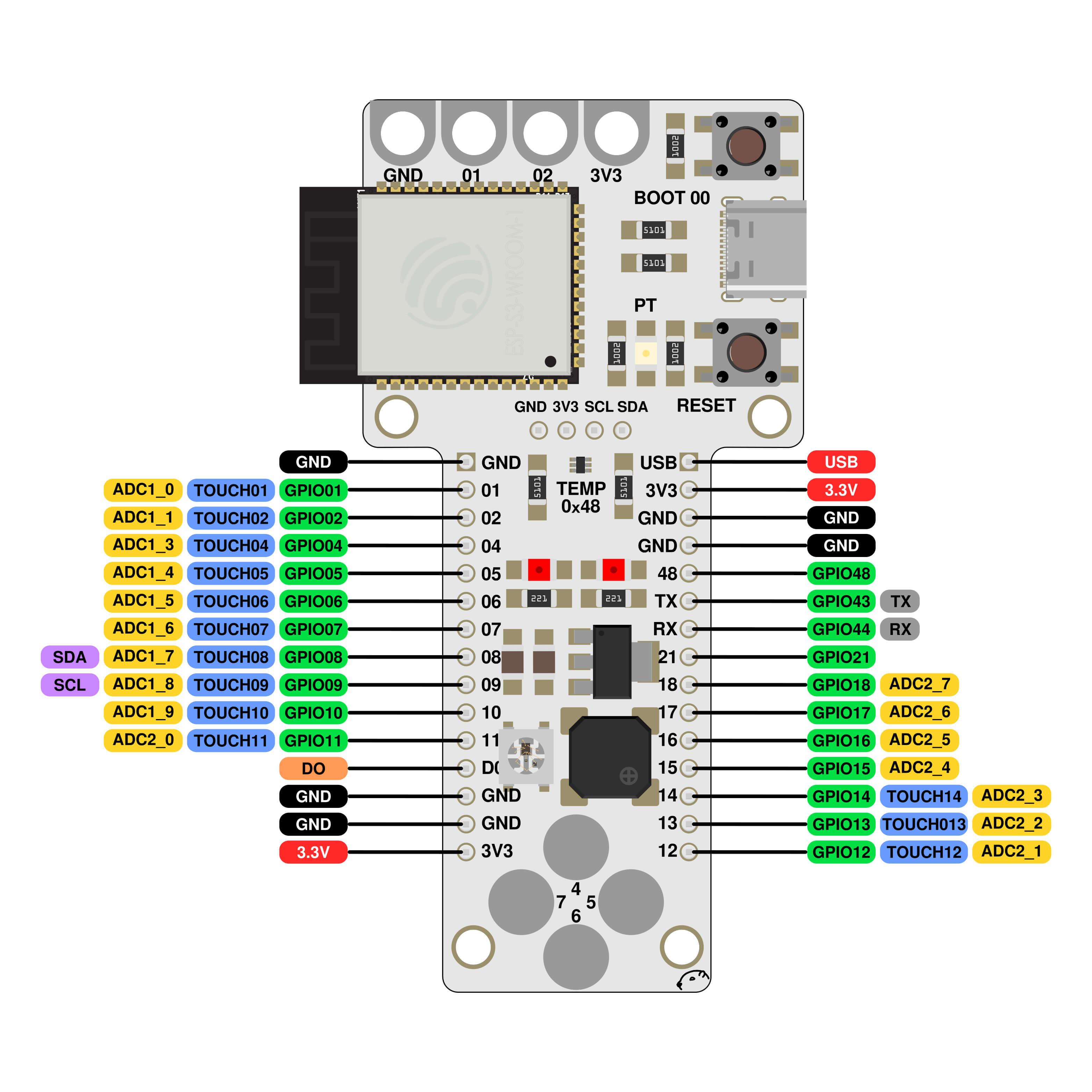
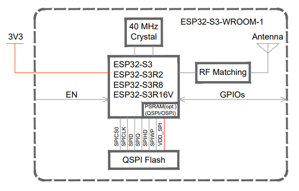
Additionally, we were each given a Barduino 4.0.2 Board to program with this week. It uses an ESP32-S3-WROOM-1 microcontroller. It is a powerful, generic WiFi + Bluetooth LE MCU module with a rich set of peripherals. It has 41 pins. Its operating voltages are between 3V and 3.6V.
3. Write a program for a microcontroller, and simulate its operation, to interact (with local input &/or output devices) and communicate (with remote wired or wireless connection)
As soon as I got my Barduino and set up the Arduino IDE on my laptop, I wanted to make sure everything was working well. To do this, I made a program for a blinking light on the board by using the provided code from TinkerCAD and changing the pinMode to match the pinout from the Barduino:
void setup()

{

  pinMode(48, OUTPUT);

}


void loop()

{

  digitalWrite(48, HIGH);

  delay(1000); // Wait for 1000 millisecond(s)

  digitalWrite(48, LOW);

  delay(1000); // Wait for 1000 millisecond(s)

}
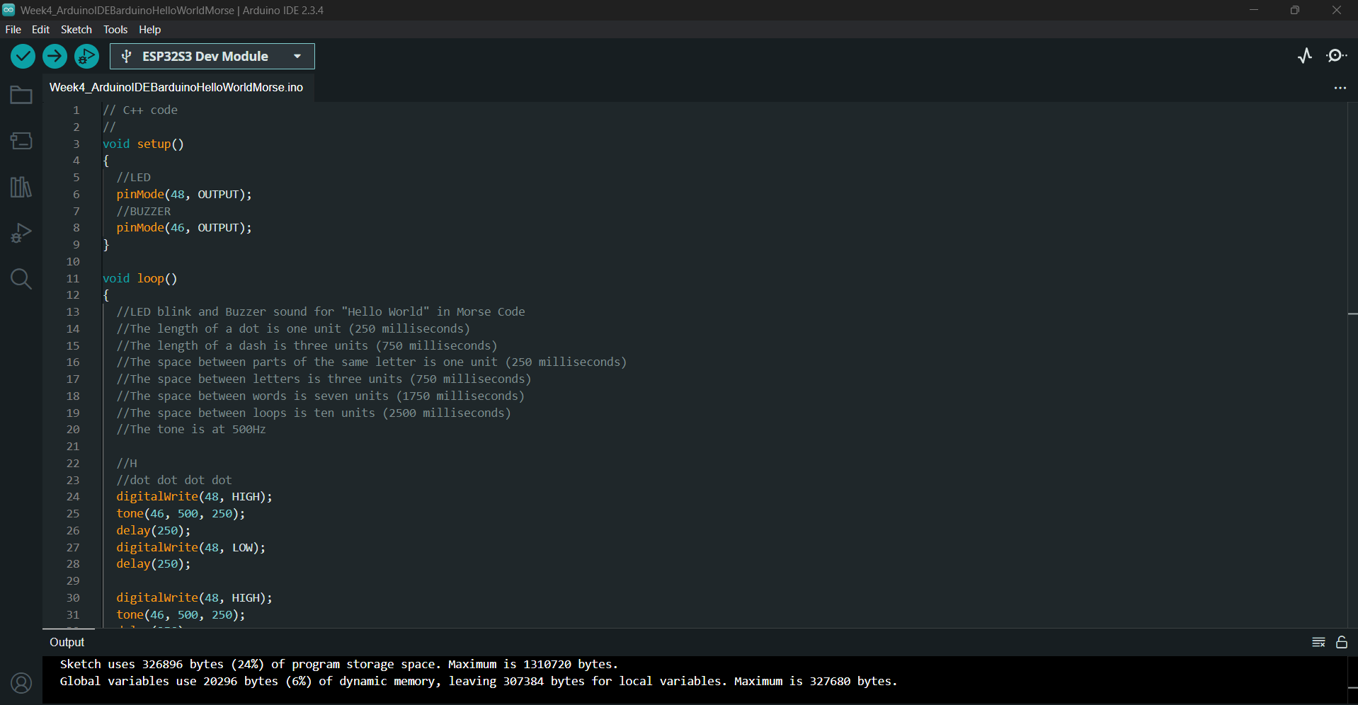
Then, I wanted to develop my programming abilities a bit more for this assignment. So, I decided to have the board communicate "Hello World" in morse code using the LED light and the buzzer:
- Created an electric circuit with an LED and a buzzer on the Arduino Uno R3 in TinkerCAD.
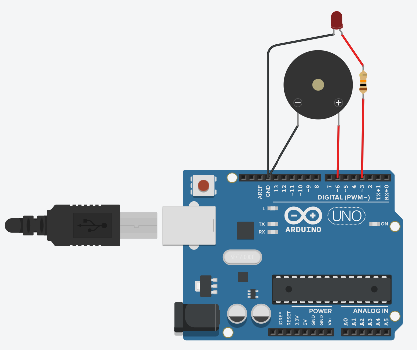
- Found out how morse code works.
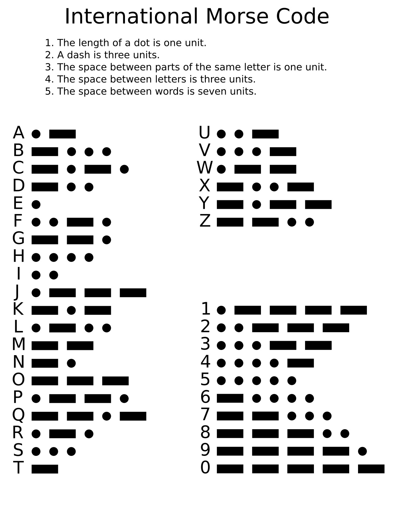
Additionally I decided the space between loops to be ten units and the tone of the buzzer to be 500Hz. - Created the following program, which is explained and annotated here:
void setup()

{

  pinMode(3, OUTPUT);

  pinMode(6, OUTPUT);

}


void loop()

{

  digitalWrite(3, HIGH);

  tone(6, 500, 250);

  delay(250);

  digitalWrite(3, LOW);

  delay(250);


  digitalWrite(3, HIGH);

  tone(6, 500, 250);

  delay(250);

  digitalWrite(3, LOW);

  delay(250);


  digitalWrite(3, HIGH);

  tone(6, 500, 250);

  delay(250);

  digitalWrite(3, LOW);

  delay(250);


  digitalWrite(3, HIGH);

  tone(6, 500, 250);

  delay(250);

  digitalWrite(3, LOW);

  delay(750);


  digitalWrite(3, HIGH);

  tone(6, 500, 250);

  delay(250);

  digitalWrite(3, LOW);

  delay(750);


  digitalWrite(3, HIGH);

  tone(6, 500, 250);

  delay(250);

  digitalWrite(3, LOW);

  delay(250);


  digitalWrite(3, HIGH);

  tone(6, 500, 750);

  delay(750);

  digitalWrite(3, LOW);

  delay(250);


  digitalWrite(3, HIGH);

  tone(6, 500, 250);

  delay(250);

  digitalWrite(3, LOW);

  delay(250);


  digitalWrite(3, HIGH);

  tone(6, 500, 250);

  delay(250);

  digitalWrite(3, LOW);

  delay(750);


  digitalWrite(3, HIGH);

  tone(6, 500, 250);

  delay(250);

  digitalWrite(3, LOW);

  delay(250);


  digitalWrite(3, HIGH);

  tone(6, 500, 750);

  delay(750);

  digitalWrite(3, LOW);

  delay(250);


  digitalWrite(3, HIGH);

  tone(6, 500, 250);

  delay(250);

  digitalWrite(3, LOW);

  delay(250);


  digitalWrite(3, HIGH);

  tone(6, 500, 250);

  delay(250);

  digitalWrite(3, LOW);

  delay(750);


  digitalWrite(3, HIGH);

  tone(6, 500, 750);

  delay(750);

  digitalWrite(3, LOW);

  delay(250);


  digitalWrite(3, HIGH);

  tone(6, 500, 750);

  delay(750);

  digitalWrite(3, LOW);

  delay(250);


  digitalWrite(3, HIGH);

  tone(6, 500, 750);

  delay(750);

  digitalWrite(3, LOW);

  delay(1750);


  digitalWrite(3, HIGH);

  tone(6, 500, 250);

  delay(250);

  digitalWrite(3, LOW);

  delay(250);


  digitalWrite(3, HIGH);

  tone(6, 500, 750);

  delay(750);

  digitalWrite(3, LOW);

  delay(250);


  digitalWrite(3, HIGH);

  tone(6, 500, 750);

  delay(750);

  digitalWrite(3, LOW);

  delay(750);


  digitalWrite(3, HIGH);

  tone(6, 500, 750);

  delay(750);

  digitalWrite(3, LOW);

  delay(250);


  digitalWrite(3, HIGH);

  tone(6, 500, 750);

  delay(750);

  digitalWrite(3, LOW);

  delay(250);


  digitalWrite(3, HIGH);

  tone(6, 500, 750);

  delay(750);

  digitalWrite(3, LOW);

  delay(750);


  digitalWrite(3, HIGH);

  tone(6, 500, 250);

  delay(250);

  digitalWrite(3, LOW);

  delay(250);


  digitalWrite(3, HIGH);

  tone(6, 500, 750);

  delay(750);

  digitalWrite(3, LOW);

  delay(250);


  digitalWrite(3, HIGH);

  tone(6, 500, 250);

  delay(250);

  digitalWrite(3, LOW);

  delay(750);


  digitalWrite(3, HIGH);

  tone(6, 500, 250);

  delay(250);

  digitalWrite(3, LOW);

  delay(250);


  digitalWrite(3, HIGH);

  tone(6, 500, 750);

  delay(750);

  digitalWrite(3, LOW);

  delay(250);


  digitalWrite(3, HIGH);

  tone(6, 500, 250);

  delay(250);

  digitalWrite(3, LOW);

  delay(250);


  digitalWrite(3, HIGH);

  tone(6, 500, 250);

  delay(250);

  digitalWrite(3, LOW);

  delay(750);


  digitalWrite(3, HIGH);

  tone(6, 500, 750);

  delay(750);

  digitalWrite(3, LOW);

  delay(250);


  digitalWrite(3, HIGH);

  tone(6, 500, 250);

  delay(250);

  digitalWrite(3, LOW);

  delay(250);


  digitalWrite(3, HIGH);

  tone(6, 500, 250);

  delay(250);

  digitalWrite(3, LOW);

  delay(2500);


}
on TinkerCAD and simulated it with the electric circuit I created.
- At first I made it so that every unit was 500 milliseconds, but after simulating it a couple of times I realized that was too long, so I brought it down to 250 milliseconds per unit.
- After it was working the way I wanted it, I copied the script into the Arduino IDE.
- Modified the program's pinModes so that it would work on the Barduino. It ended up like this.
- Connected the Barduino board into the computer.
- Set up the IDE so that it was connected to the board.
- Verified the program to make sure it would work.
- Uploaded the program into the Barduino board and saw it come to life.