Week 8
Electronics Production
Week Outline
- Wednesday: Global Class in Electronics Production.
- Thursday: Local Class in Electronic Production and Milling.
- Wednesday: Global Review.
Global Class
For this week's Global Class, Neil ran us through the different steps in PCB production and the diffeents systems that can be used. Then, he discussed the different materials that can be used. Then, he introduced us to different board houses we can use if needed. Then, he ran us through the process of PCB assembly. He also discussed CAM and debugging tools.
Local Classes
On Thursday, Dani showed us the workflow for using our Roland CNC machines to produce our PCB designs from Kicad. The workflow goes as follows:
The workflow for preparing the files goes as follows:
- On the PCB editor of your project on Kicad, select the "Plot" option.
- Select "PDF" as a plot format.
- Select th e output directory for where you want the file to be saved in your computer.
- Right click on top of the "Include Layers" list and select "Deselect all layers".
- Select the "F.Cu" layer only.
- In "PDF Options", select "Black and White" as the output format.
- Click "Plot" on the bottom right.
- Open the newly generated PDF on Inkscape.
- Create 4 layers: "Traces", "Holes", "Outline", and "Background".
- Move each component to it's corresponding layer by right clicking on one and then selecting "Select same" to select all the necessary components.
- Invert colors so that traces are white, holes are black, and outlines are white.
- Create a square with black fill and stroke in the "Background" layer that encompasses the whole design and has at least 0.8mm offset outside.
- Duplicate the square twice.
- Move each one of the squares from the "Background" layer into the other layers.
- Delete "Background" layer.
- Invert the colors on the square in the "Holes" layer so that it is white.
- On "File", select "Export" and go to "Export Batch".
- Make sure all layers are selected and have the correct colors (Traces in white with black background, Holes in black with white background, Outline filled in white with black background).
- Change the DPI to 1000.
- Export each layer as an individual PNG.
- Open modsproject.org on the web browser.
- Right click anywhere on the screen and select "Programs".
- Select "Open Program".
- Under "Machines", go to "Roland" and then go to "SRM-20 Mill" and select "Mill 2D PCB".
- Go to the "Read PNG" module, click on "Select PNG File", and then select the PNG for the "Traces" layer.
- Change the dpi to 1000.
- On the "Set PCB Defaults" module, click on the "mill traces (1/64)" button.
- On the "Mill Raster 2D" module, change the "cut depth" and "max depth" to 0.15mm.
- On the "Roland SRM-20 milling machine" module, change the "speed" to 2mm/s and the "origin" on all 3 axises to 0.
- Make sure both toggle switches on the right are turned on.
- Go back to the "Mill Raster 2D" module and click on "calculate". This will download the mill raster file automatically.
- Go back to the "Read PNG" module, click on "Select PNG File", and then select the PNG for the "Holes" layer.
- Change the dpi to 1000.
- On the "Set PCB Defaults" module, click on the "mill traces (1/32)" button.
- On the "Roland SRM-20 milling machine" module, change the "speed" to 2mm/s and the "origin" on all 3 axises to 0.
- Make sure both toggle switches on the right are turned on.
- On to the "Mill Raster 2D" module, click on "calculate". This will download the mill raster file automatically.
- Go back to the "Read PNG" module, click on "Select PNG File", and then select the PNG for the "Outline" layer.
- Change the dpi to 1000.
- On the "Set PCB Defaults" module, click on the "mill traces (1/32)" button.
- On the "Roland SRM-20 milling machine" module, change the "speed" to 2mm/s and the "origin" on all 3 axises to 0.
- Make sure both toggle switches on the right are turned on.
- On to the "Mill Raster 2D" module, click on "calculate". This will download the mill raster file automatically.
- Load all 3 mill raster files into a USB.
The workflow for milling the boards goes as follows:
- Insert the USB with the mill raster files into the laptop on the Roland machine.
- Make sure the machine is turned on and the laptop is properly connected.
- Dust of the milling base with a brush.
- Put double sided tape on the back of a copper board and stick the board down on the milling base.
- Load the 1/64" drill bit into the coupling.
- Move the base so that the bit is on the bottom left of the plate.
- Set the XY zero.
- Slowly move the carrier down until it is close to the plate.
- Loosen the grub screw holding the drill bit into the coupler and let the bit touch the top of the plate.
- Re-tighten the grub screw on the holder and set the Z zero.
- On the Roland software, click "cut".
- Click on "delete all" to make sure you have no files on queue.
- Add the raster file for your "Traces" layer and then click "output", this will begin the cut.
- Make sure the machine is cutting at the appropriate level and then wait for it to be done.
- Once the cut is finished, replace the 1/64" drill bit for the 1/32" drill bit.
- Swap out the 1/64" drill bit for the 1/32" drill bit.
- Slowly move the carrier down until it is close to the plate.
- Loosen the grub screw holding the drill bit into the coupler and let the bit touch the top of the plate.
- Re-tighten the grub screw on the holder and re-set the Z zero.
- On the Roland software, click "cut".
- Click on "delete all" to make sure you have no files on queue.
- Add the raster file for your "Holes" layer and then click "output", this will begin the cut.
- Make sure the machine is cutting at the appropriate level in the appropriate places and then wait for it to be done.
- Once it's done, on the Roland software, click "cut".
- Click on "delete all" to make sure you have no files on queue.
- Add the raster file for your "Outline" layer and then click "output", this will begin the cut.
- Make sure the machine is cutting at the appropriate level in the appropriate places and then wait for it to be done.
- Remove the copper plate and you're done!
Assignments
1. Characterize the design rules for your in-house PCB production process as a group.
The documentation of the work we did can be found here.
2. Submit a PCB design to a board house as a group.
The documentation of the work we did can be found here.
3. Make and test a microcontroller development board that you designed.
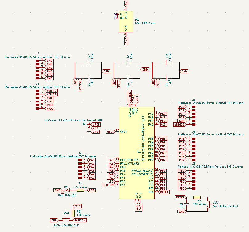
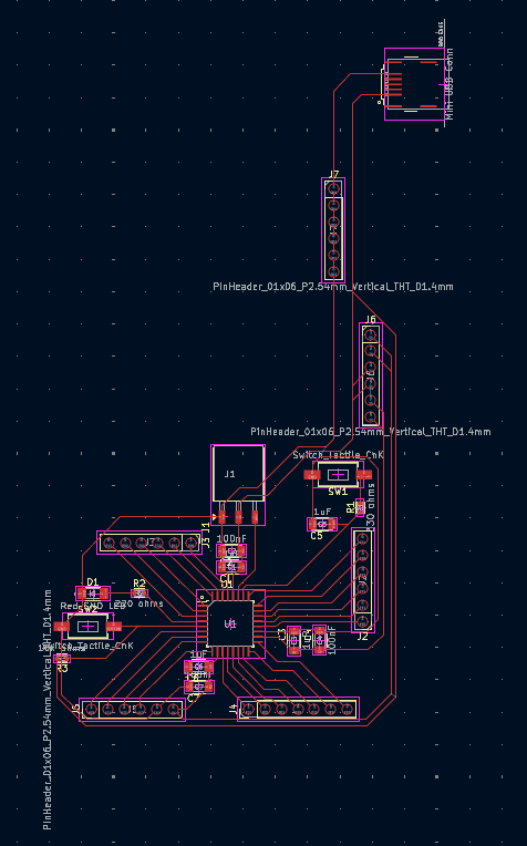
I decided to make the microcontroller development board I designed in Week 6:
First Prep
- Exported the copper layers from Kicad by plotting them into a PDF.
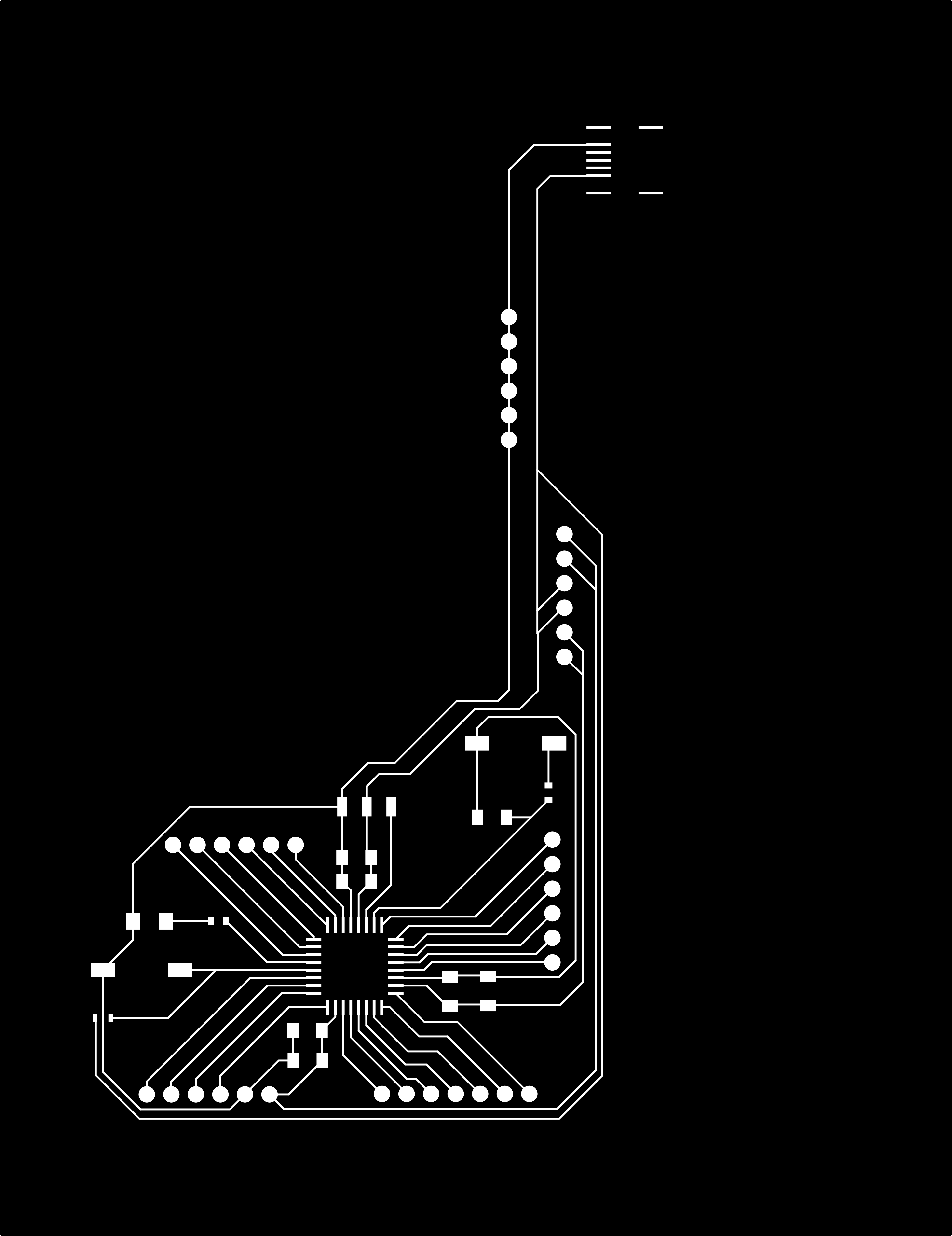
- Opened the PDF on Inkscape and followed the workflow Dani taught us in class.
- I wanted my board to have the shape of a musical note, so instead of having done the outline trace on Kicad, I imported an SVG from the internet and modified it on inkscape.
- Created a square to act as the background in order for all the layers to have the same size. Then made 2 exact copies of it and moved the 3 squares into each one of the other layers, then deleting the background layer.
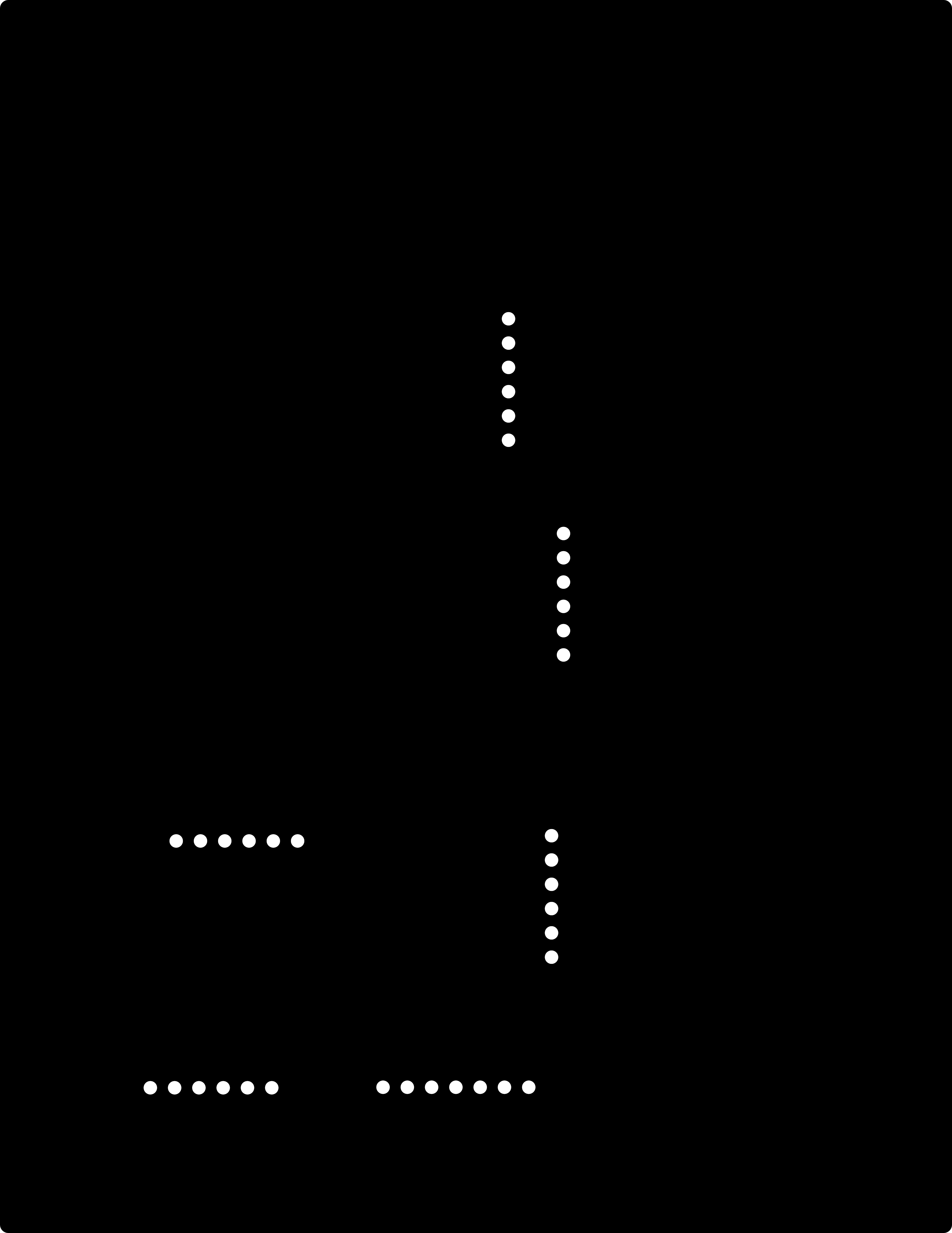
- Made sure everything was the color it was supposed to be (or so I thought) and then exported all the layers (individually) as PNGs with a 1000dpi.

- Opened modsproject.org and followed the workflow Dani taught us in class for each layer.
- Exported all the mill raster files into a USB and plugged it into the laptop on the Roland machine.
The mill raster file for the traces layer can be downloaded here. The mill raster file for the holes layer can be downloaded here. The mill raster file for the outline layer can be downloaded here.
First Milling Attempt
- Cleaned the milling surface on the machine of dust particles with a brush.
- Put double sided tape on a brand new copper plate and stuck it to the milling surface.
- Installed the 1/64" thick drill bit on the machine to cut the traces.
- Zeroed the machine.
- Loaded up the file and started the cut.
- Once the cut was done, I changed the 1/64" drill bit for the 1/32" drill bit on the machine to cut the holes and the outline.
- I kept the zero on the x and y but re-zeroed the z axis (because I changed drill bit).
- I loaded up the file for the holes and started the cut.
- Something looked wrong, so I stopped the cut and had a look. If you payed close attention to the way I colored my layers, you already know I got the colors for the holes mixed up. Instead of being white on black background, they were suppossed to be black on a white background, so that the machine knew to just tap the holes and not drill around them. So I unfortunately ruined a perfectly looking board:
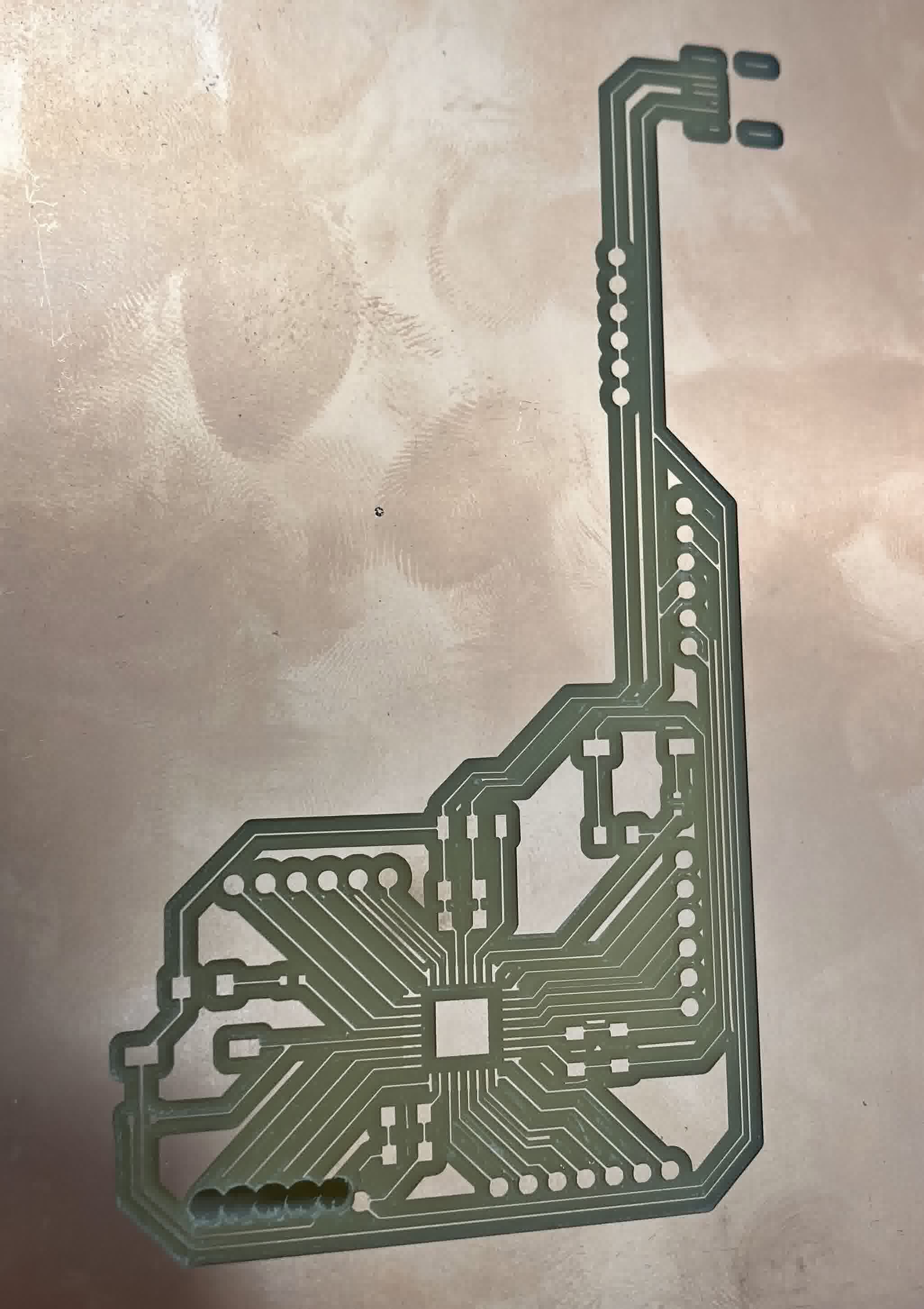
While it was dissapointing, this did not disencourage me. I removed the plate and re-started.
Second Milling Attempt
- Cleaned the milling surface on the machine of dust particles with a brush.
- Put double sided tape on a brand new copper plate and stuck it to the milling surface.
- Changed the 1/32" drill bit for the 1/64" drill bit on the machine.
- Zeroed the machine.
- Re-loaded up the traces file and started the cut.
- While the machine was cutting, I went back to Inkscape to change the colors on the holes layer, and exported it as a PNG with a 1000dpi.
- Opened modsproject.org and followed the workflow Dani taught us in class for the holes layer.
- Once the machine was done cutting the traces layer, I exported the mill raster file for the new holes layer into the USB and plugged it into the laptop on the Roland machine.
- Changed the 1/64" drill bit for the 1/32" drill bit on the machine to cut the holes and the outline.
- Kept the zero on the x and y but re-zeroed the z axis (because I changed drill bit).
- Loaded up the file for the holes and started the cut.
- Once the machine was done with the holes, I loaded up the file for the outline and started to cut.
- After the machine was done, I removed the entire copper plate and cleaned off the dust with a brush.
- I extracted my music note shaped PCB to notice it was not perfect:
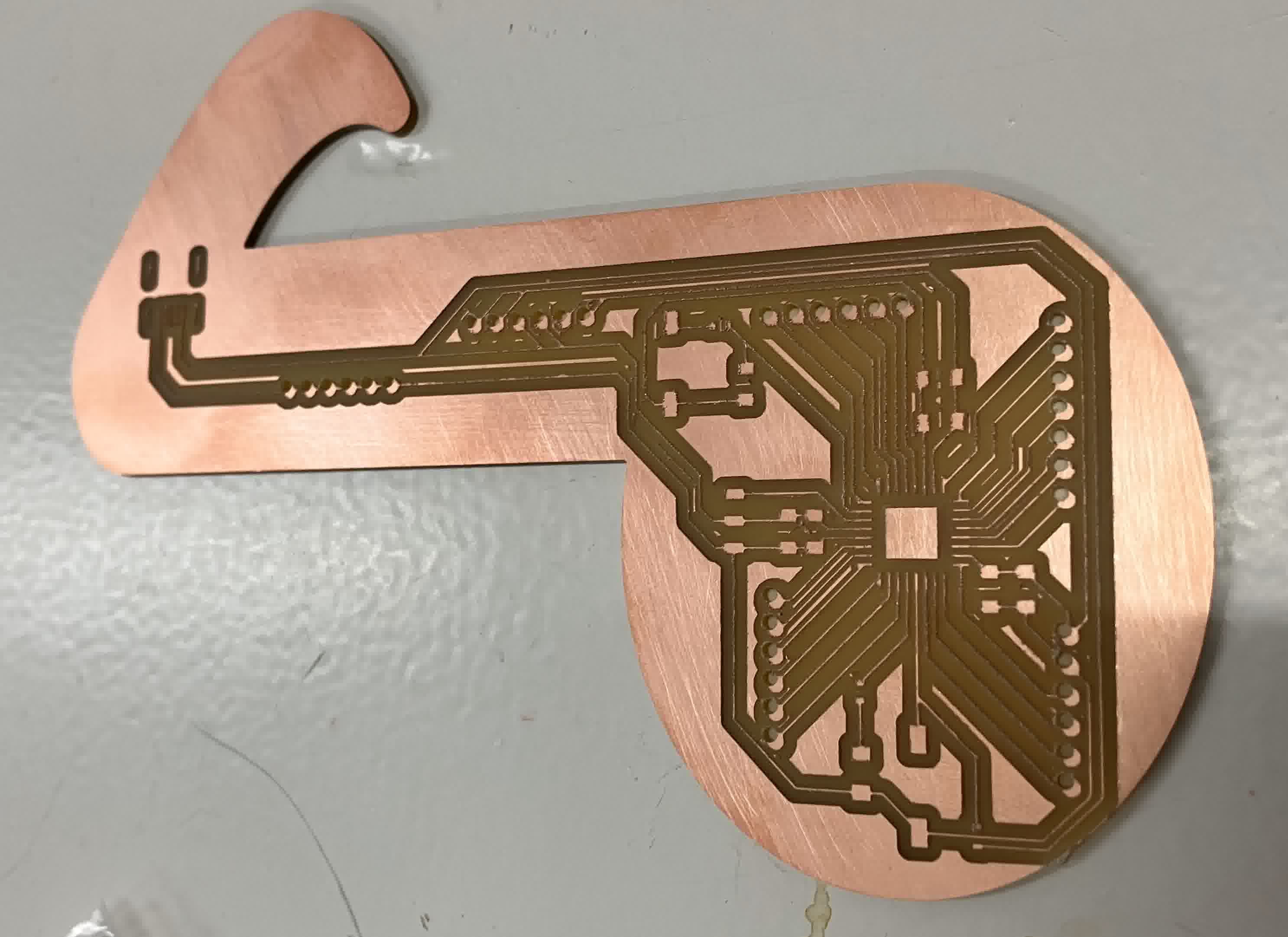
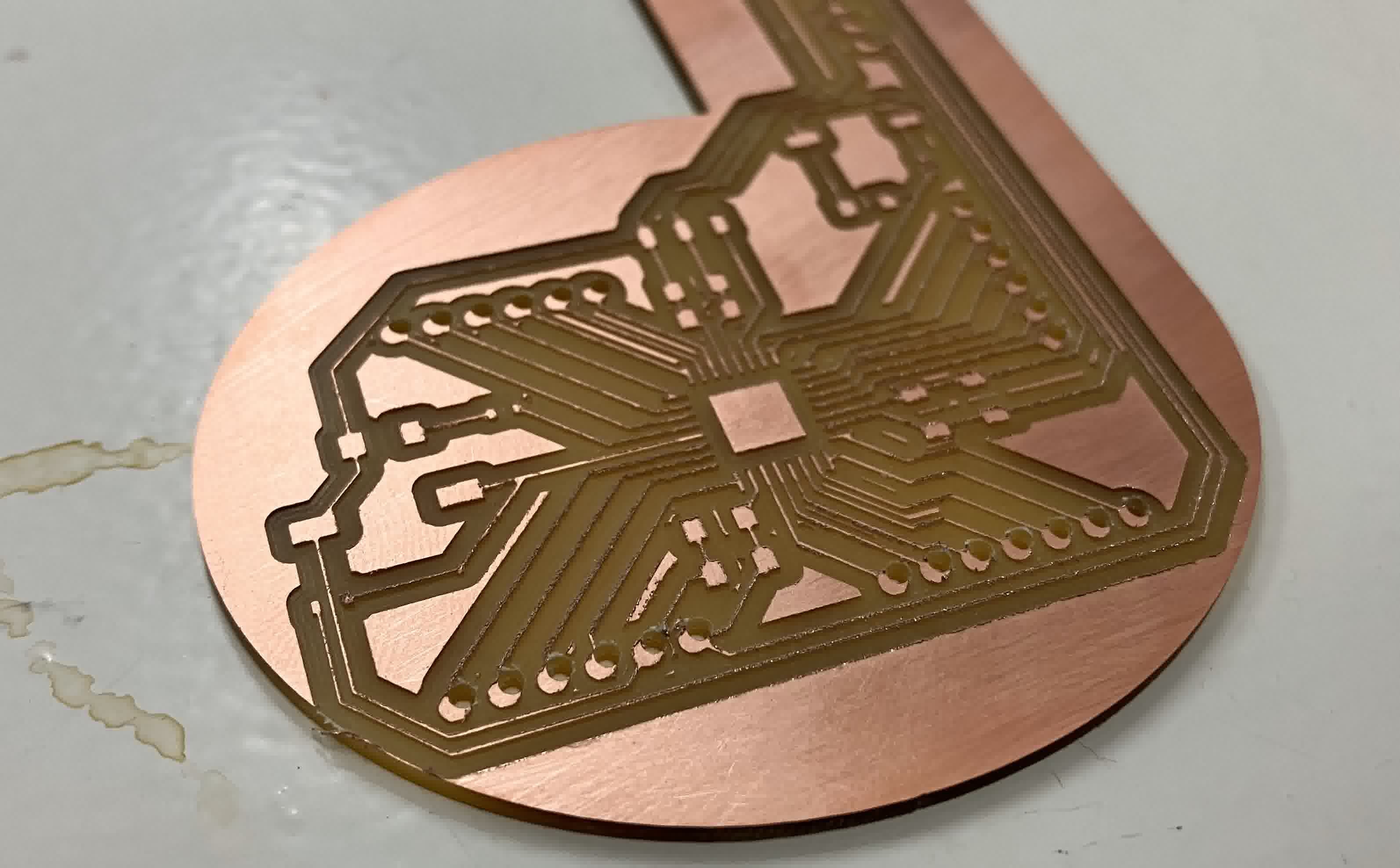
The traces were not as clean as the previous board. It was also as if both the holes and the outline layers had moved diagonally upwards a couple of mm. Below is a closer look at the skewed holes:
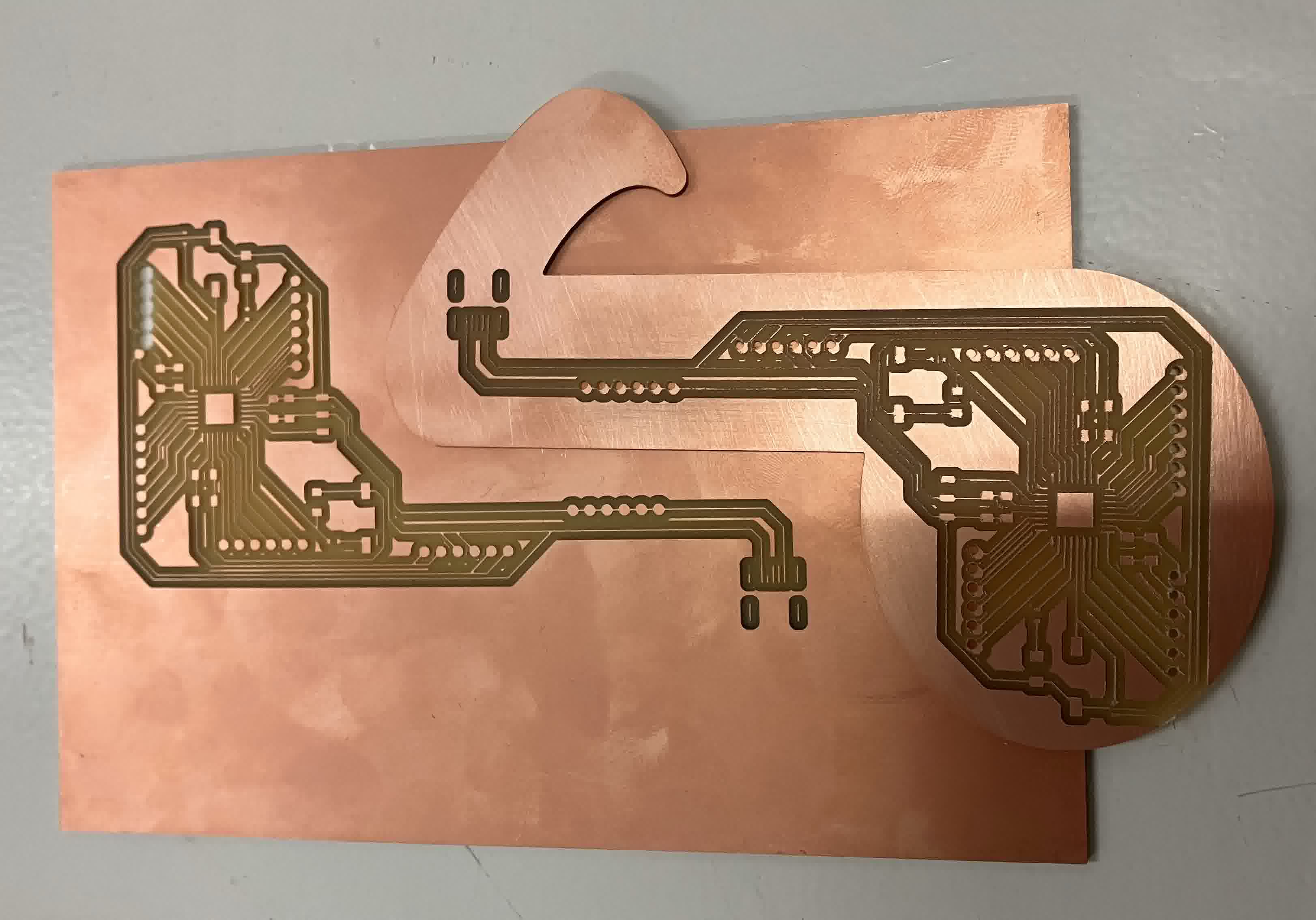
Below is a side by side comparison of both the first and second attempts:
The mill raster file for the modified holes layer can be downloaded here.
Second Prep
Although dissappointed, I was still not disencouraged. I took the opportunity and went back to Kicad to change the traces from 0.2mm thick to 0.3mm thick everywhere I was able to. Then I:
- Re-exported the newly modified copper layers from Kicad by plotting them into a PDF.
- Opened the PDF on Inkscape.
- Separated the components into 4 layers: one for the holes, one for the traces, one for the outline, and one for the background.
- Re-imported the musical note SVG into the outline layer and modified it to work with what I needed.
- Created a square to act as the background in order for all the layers to have the same size. Then made 2 exact copies of it and moved the 3 squares into each one of the other layers, then deleting the background layer.
- Made sure everything was the color it was supposed to be and then exported all the layers (individually) as PNGs with a 1000dpi.
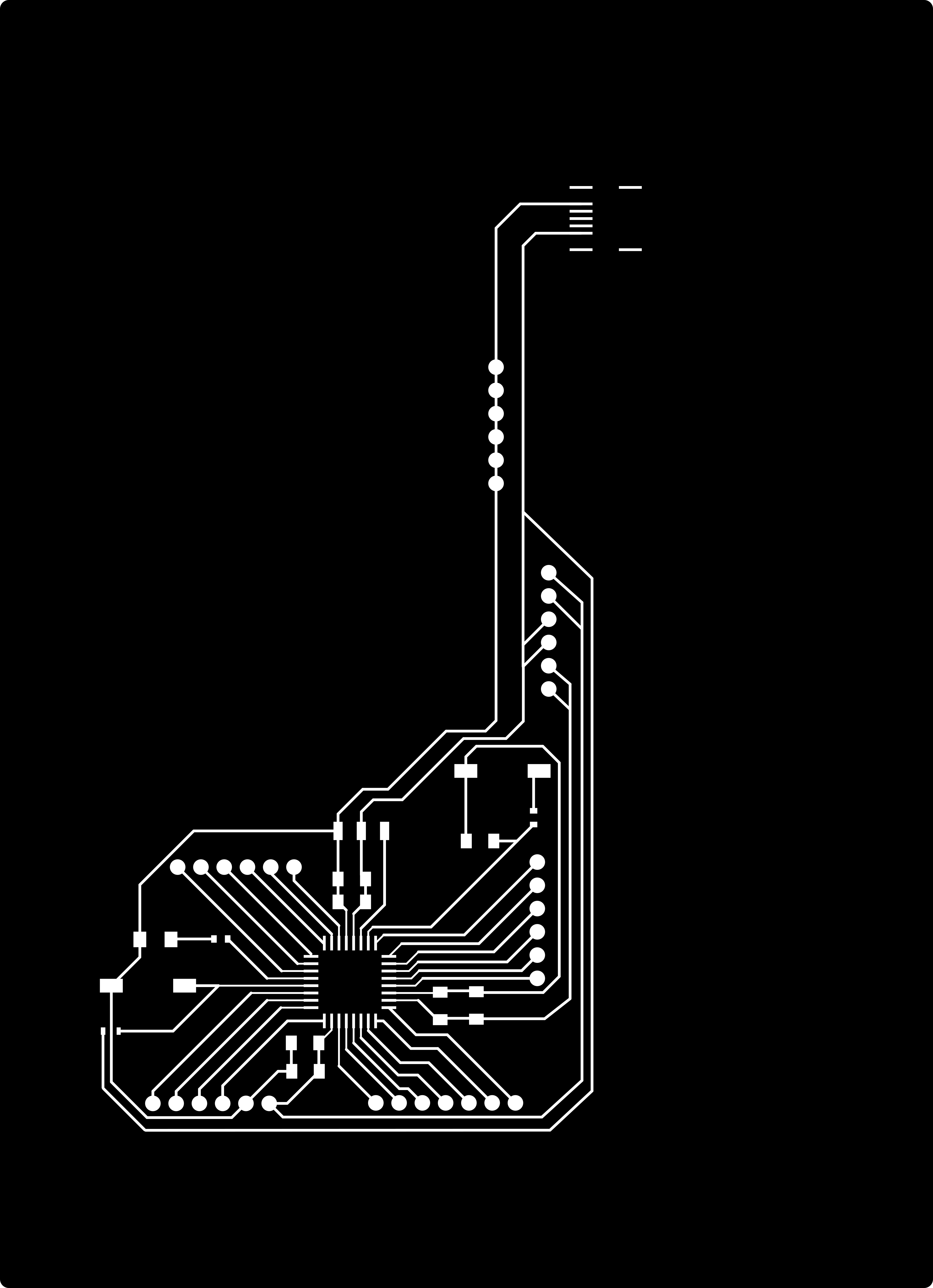


- Opened modsproject.org and followed the workflow Dani taught us in class for each layer.
- Exported all the mill raster files into a USB and plugged it into the laptop on the other Roland machine, as the one I used before proved to be having issues with coordinates on all planes not only for me but for others as well.
The mill raster file for the traces layer can be downloaded here. The mill raster file for the holes layer can be downloaded here. The mill raster file for the outline layer can be downloaded here.
Third Milling Attempt
- Cleaned the milling surface on the machine of dust particles with a brush.
- Put double sided tape on a brand new copper plate and stuck it to the milling surface.
- Installed the 1/64" thick drill bit on the machine to cut the traces.
- Zeroed the machine.
- Loaded up the file and started the cut.
- The traces went well!
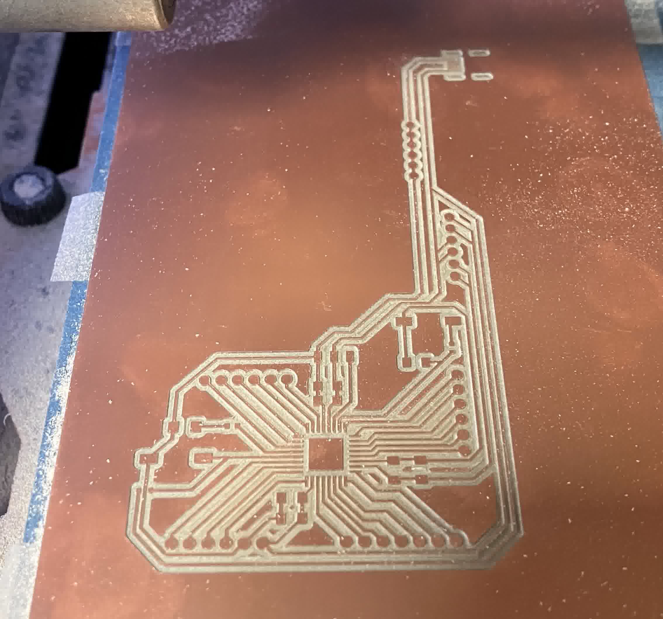
- Changed the 1/64" drill bit for the 1/32" drill bit on the machine to cut the holes and the outline.
- Kept the zero on the x and y but re-zeroed the z axis (because I changed drill bit).
- Loaded up the file for the holes and started the cut.
- The holes went well too!
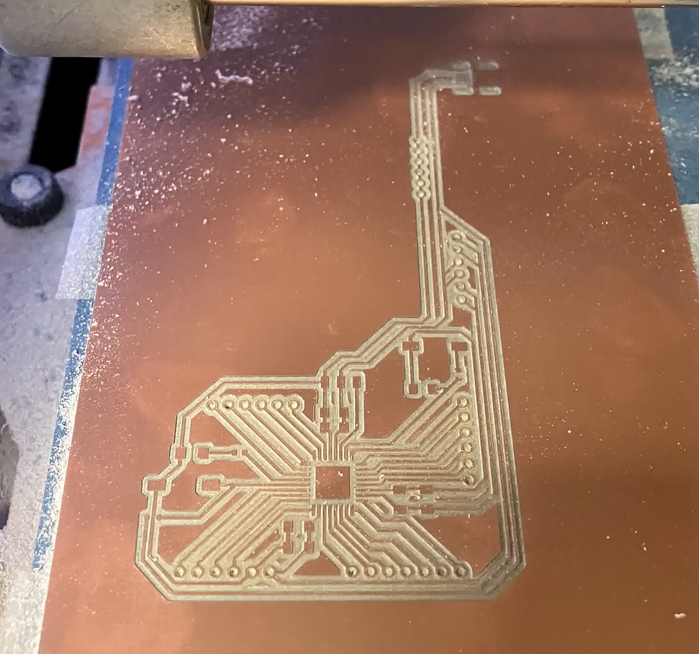
- Loaded up the file for the outline and started to cut.
- The outline also went well, so massive success overall!
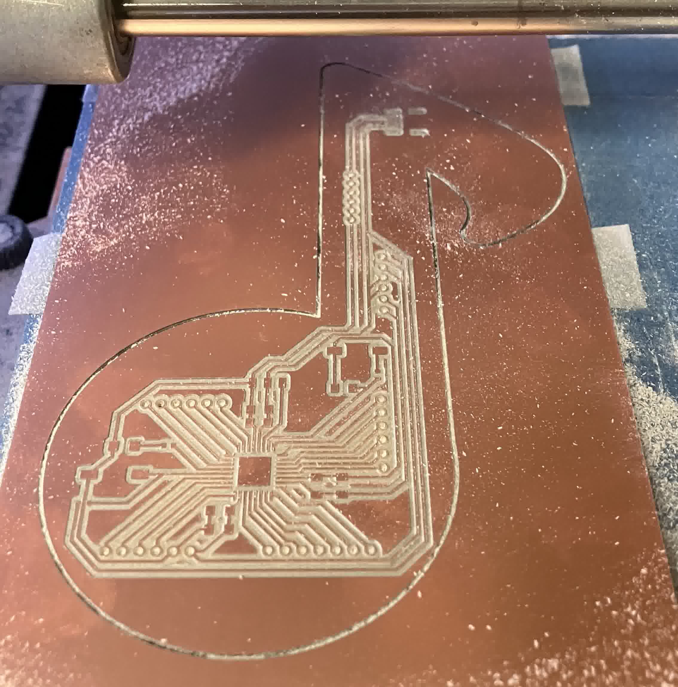
- After the machine was done, I removed the entire copper plate and cleaned off the dust with a brush.
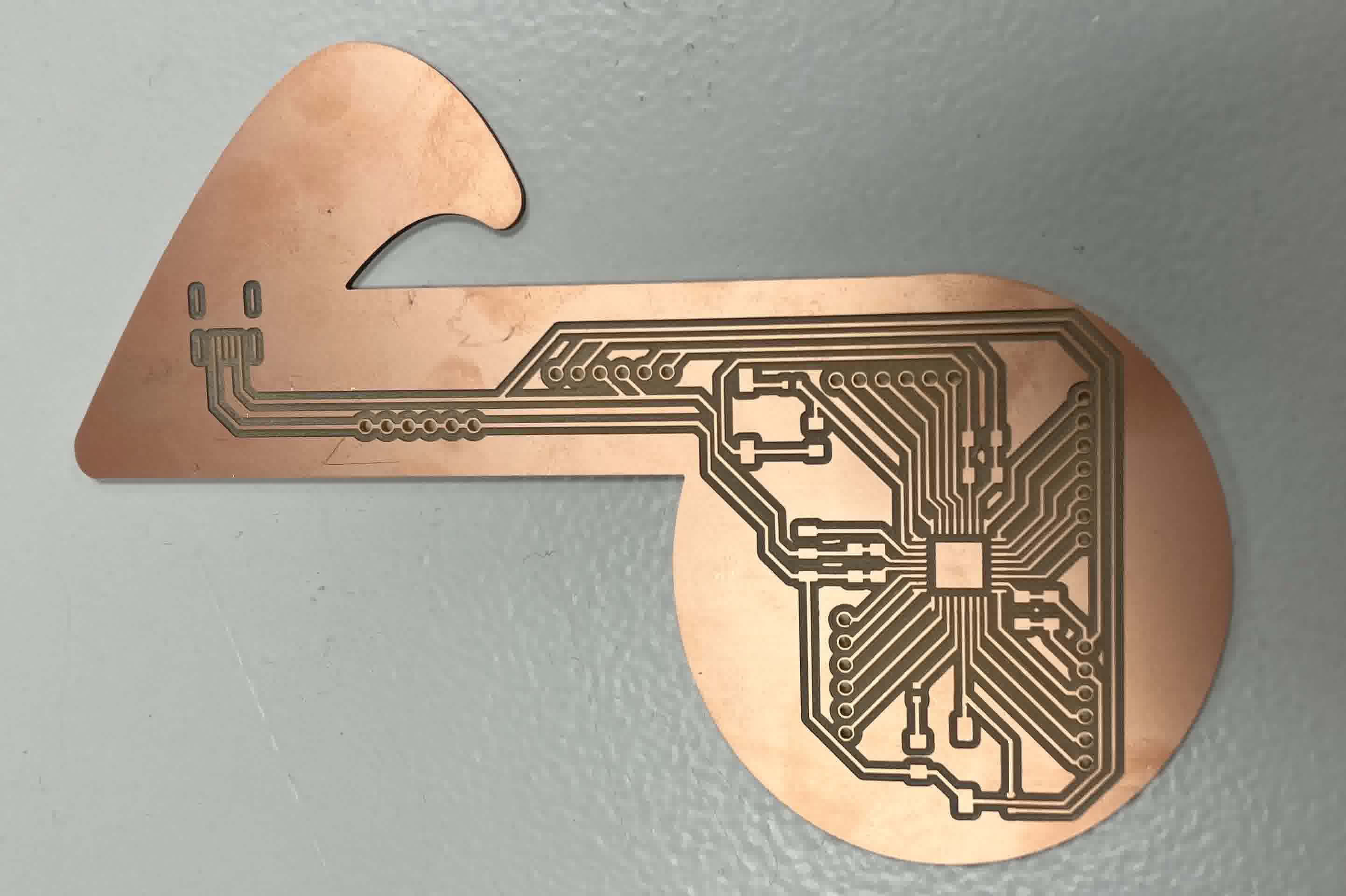
Everything went well this time (third time is the charm), so I was ready to move on to the next step: assembling!
Assembling
I first started by gathering my components from the lab. In order to do this in an orderly manner, Dani taught us the technique pictured below, where you put double sided tape on a piece of paper and annotate what you're grabbing:
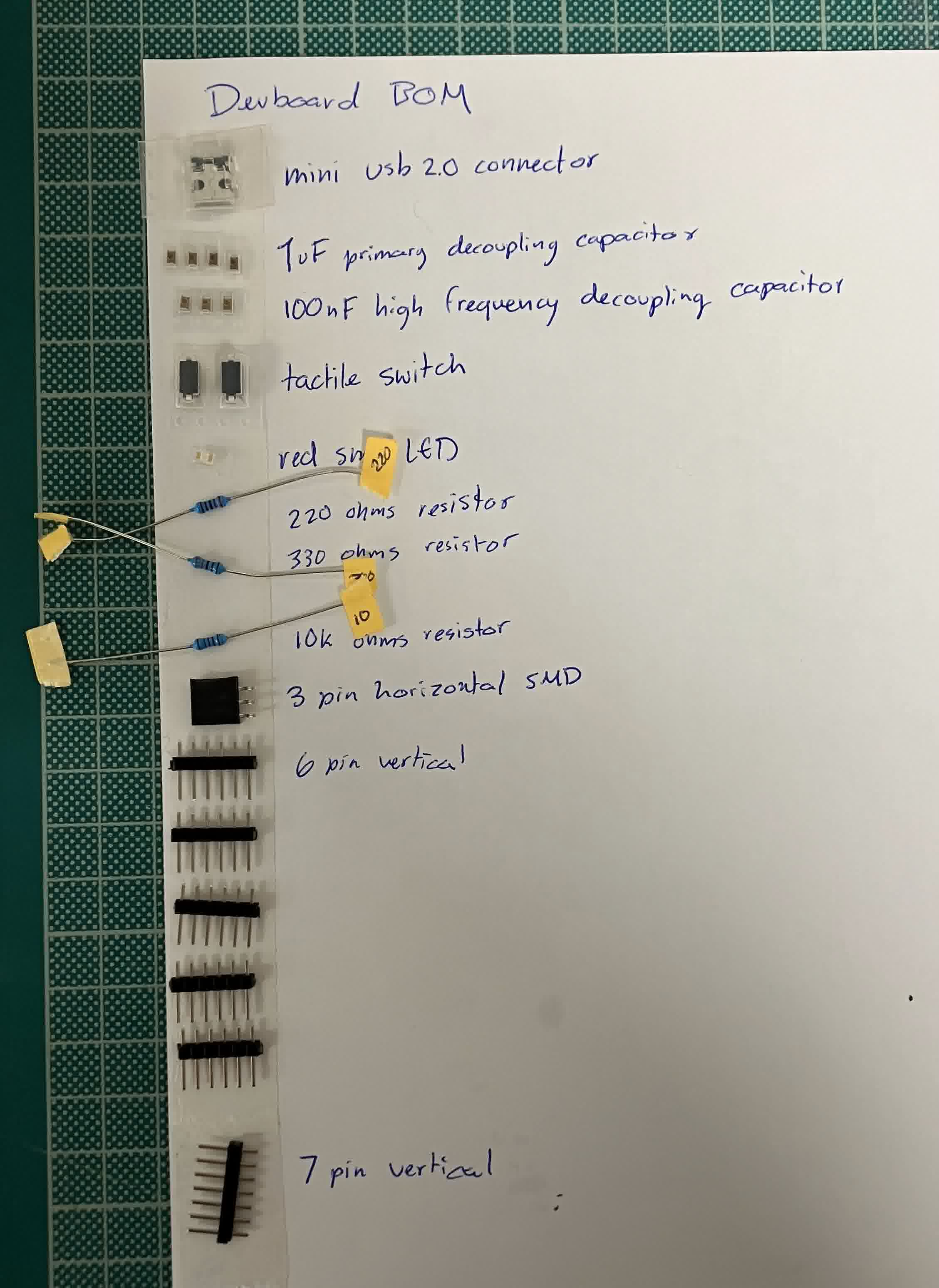
After I gathered everything I needed (and received my microcontroller in the mail), I got to soldering!
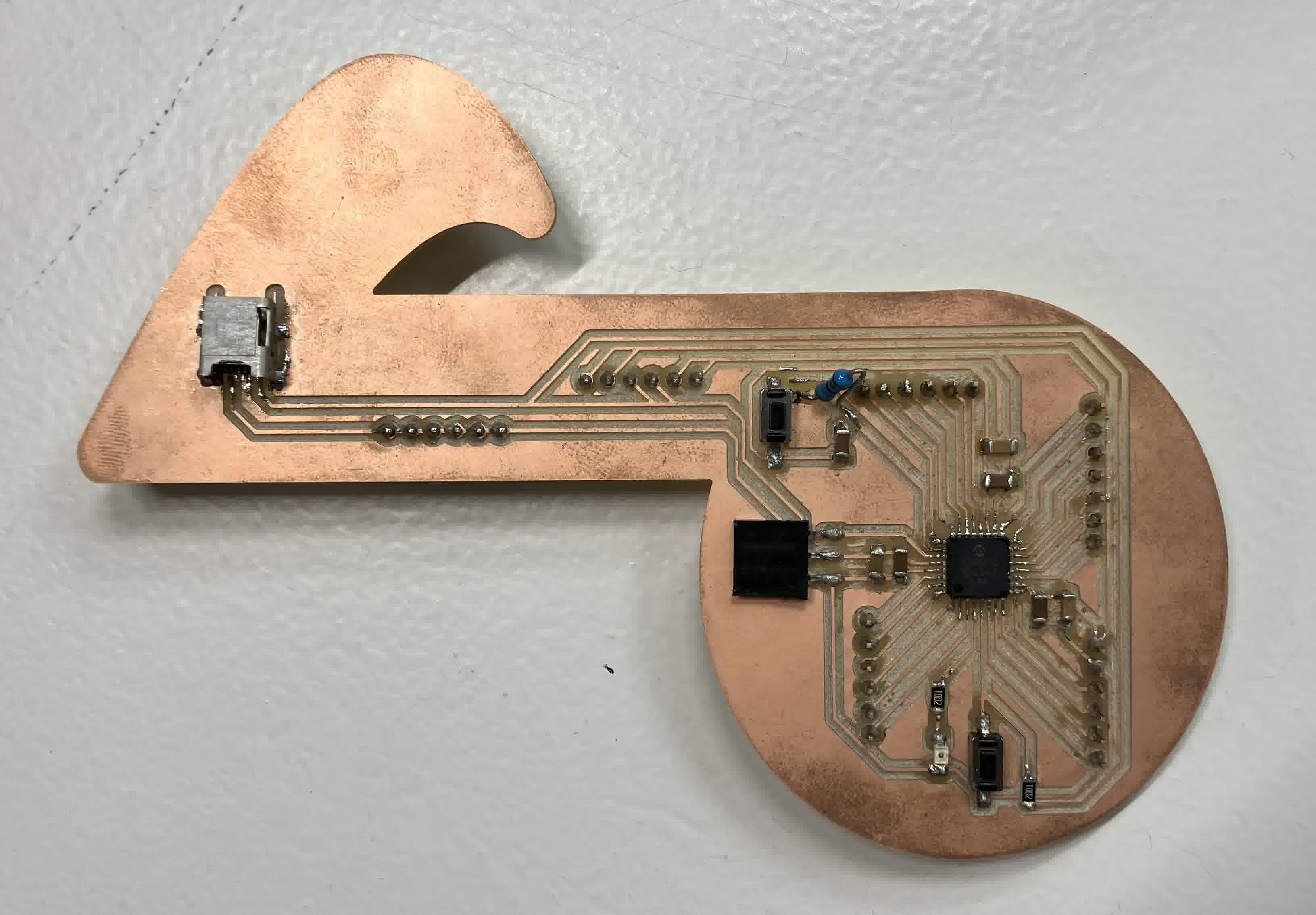
I replaced some of the resistors for SMD style when I realized we had some available.
Testing
Since my microcontroller is an AVR128DB32, I had to install DxCore in order to use the Arduino IDE for it.
Once my IDE was set up, I followed these instructions to link my board to the computer via a programmer in order to be able to use the Arduino IDE. So I hooked up a Quentorres programmer to my board with a 1k resistor in between the Tx and Rx lines going into the UPDI line.
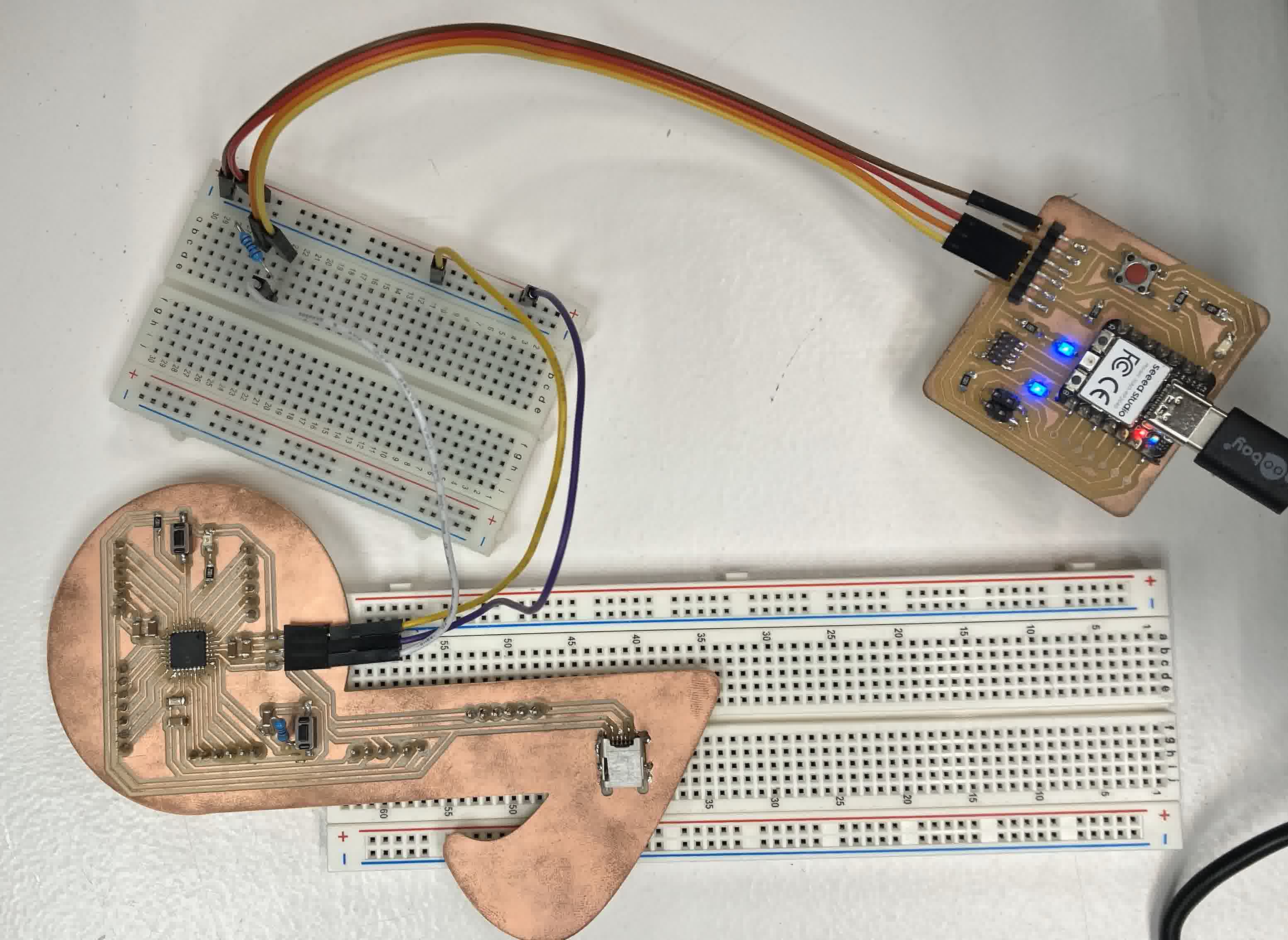
Once the wiring was done, I launched the Arduino IDE. On the upper left side, in "Tools", I:
- Selected Board > DxCore > AVR DB-series (no bootloader).
- Selected the port which the Quentorres was connected in.
- Selected Chip > AVR128DB32.
- Selected Programmer > SerialUPDI - SLOW: 57600 baud.
- Clicked on "Burn Bootloader" and managed to burn the bootloader.
After doing this, I realized I was going to have to use this set up any time I wanted to program one of my chips, so I designed and built my own programmer, based off of the Quentorres but with the specifications of what I need. You can read my documentation for this here. Once I had that, I loaded Arduino IDE's "Blink" example program, which can be acquired on the top left corner, in "File" > Examples > 01. Basics > Blink and modified it to look like this:
// the setup function runs once when you press reset or power the board

void setup() {

  // initialize digital PIN_PA6 as an output.

  pinMode(PIN_PA6, OUTPUT);

}


// the loop function runs over and over again forever

void loop() {

  digitalWrite(PIN_PA6, HIGH);  // turn the LED on (HIGH is the voltage level)

  delay(10000);                      // wait for a second

  digitalWrite(PIN_PA6, LOW);   // turn the LED off by making the voltage LOW

  delay(10000);                      // wait for a second

}