Week 3
Computer-Controlled Cutting
First week of actual fabrication!
Week Outline
- Wednesday: Global Class on Computer-Controlled Cutting.
- Thursday: Local Class on Laser Cutting Basics. Learned how to use the Laser and Vinyl Cutters at the lab. Local Class on Parametric Design with Fusion. We started our group assignment. I started working on my parametric press-fit kit design on Fusion.
- Friday: Local Class on Parametric Design with Grasshopper. I caught up on my weekly documentation and continued working on my parametric press-fit kit design on Fusion.
- Monday: Local Class on Parametric Design with Blender Geometry Nodes. I finished my Luban Lock Ball Puzzle design, first cut, and re-design. I also caught up on my documentation.
- Tuesday: I finished my Planetary Gears design and caught up on my documentation.
- Wednesday: I cut my Planetary Gears design and the AC37 logo. I caught up with my documentation. Global Review.
- Thursday I cut my Planetary Gears design modifications and my Luban Lock Ball Puzzle corrected design.
Global Class
On this week's global class, Neil gave us an introduction into computer controlled cutting. He gave us an overall idea of what tools can be used for the process (knives, print/cut, laser, plasma, waterjet, hot wire, wire EDM), as well as which CAD and CAM input softwares are useful for what type of tool. He did a deep dive into vinyl and laser cutters. For the vinyl cutter, he covered applications, materials, machine settings, and some techniques for using them. For the laser cutter, he covered applications, LASER theory, mechanisms, cutting processes, machine airflow, safety recommendations, and machine settings. When he talked about the laser cutter applications, he did a deep dive into press-fit constructions and the different types of joints that can be used in them.
Local Classes
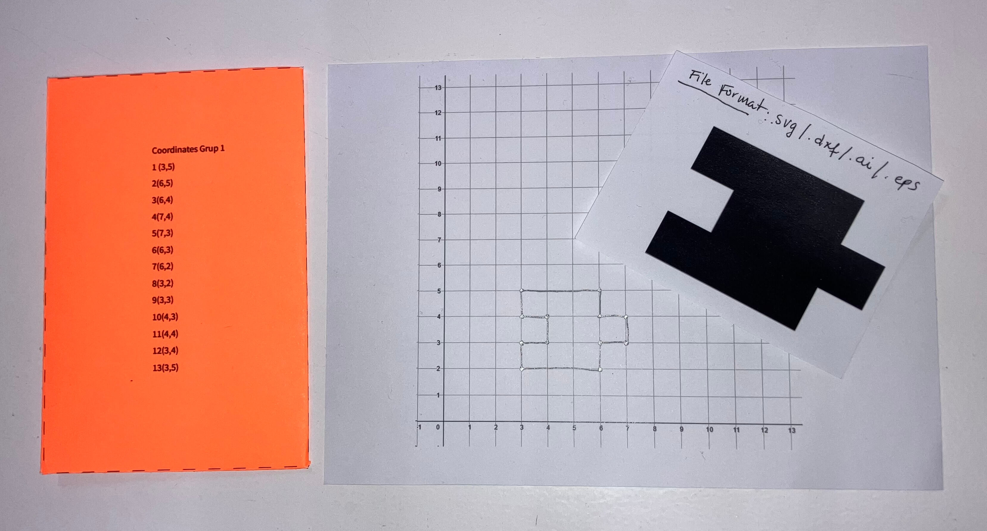
On Thursday, we started the day with a class on laser cutting basics. We did an exercise where we paired up and one person read given coordinates to another person, who was drawing them on a piece of paper. This way we created basic images and opened up the conversation about how a laser cutter acts upon a set of instructions that come from the designs. Below is an image of my group's instructions, design, and what the design should look like at the end.
After this, we covered the basic concepts of how laser cutters work. We then headed over to the machines we have at the lab to learn how to operate them properly and safely.
After learning how to use the laser cutters, we moved on to learning how to use the vinyl cutters. Julia taught us how to use both machines that we have here at the lab and then did some examples with both of them.
Parametric Design with Fusion
On Thursday afternoon, Didac gave us a brief explanation of what parametric design is and then compared it with non-parametric design, giving us a range of pros and cons for both of them so we could better understand. Then, he proceeded to show us how to do parametric design in Fusion. We did the following module:
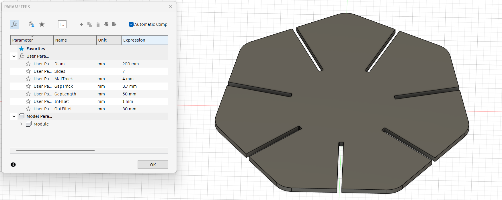
In order to achieve this, we:
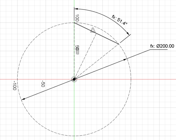
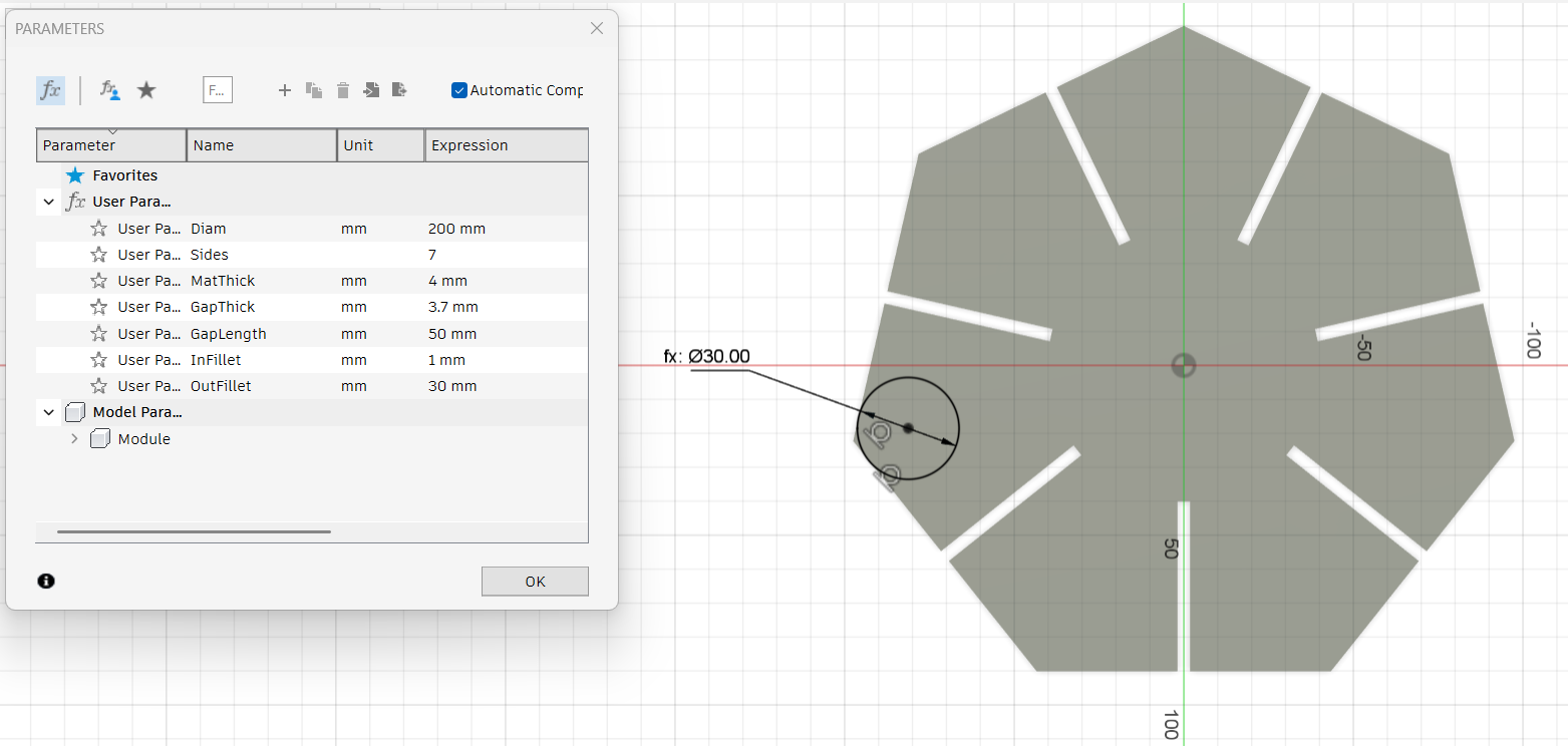
- Created a sketch. Drew a construction circle on the point of origin. Established the parameters we wanted for our shape.
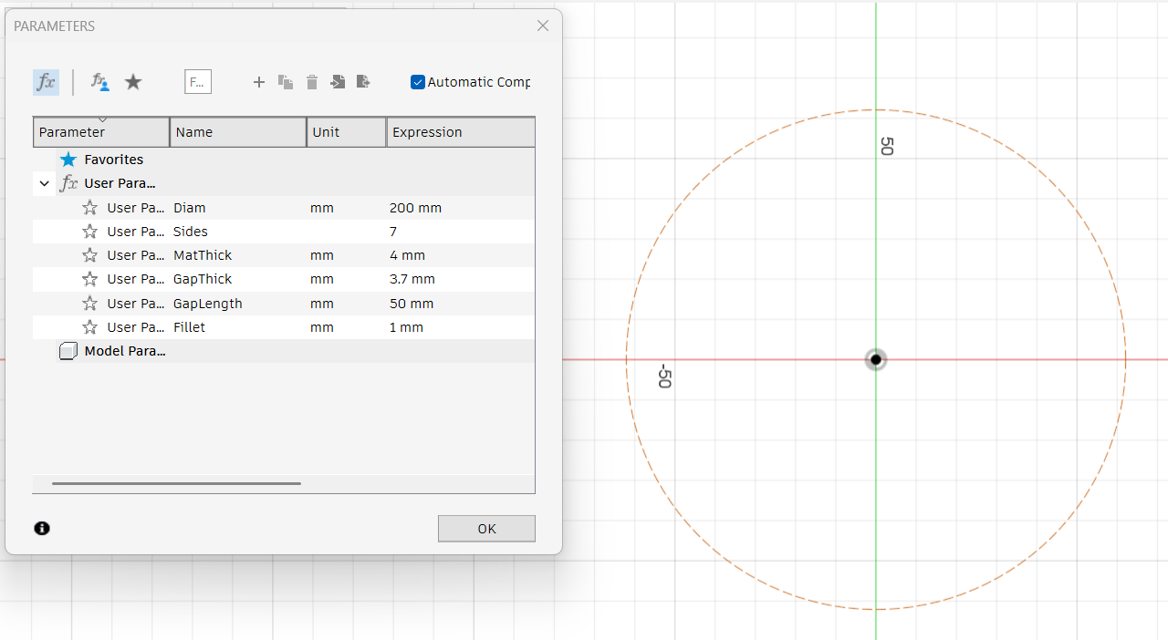
- Determined the size of the circle with the parameters created.
- Created 2 construction lines from point of origin to any random point on the circle.
- Created a distance between the 2 previously created lines that was determined by the amount of sides the shape is going to have (the value for distance was 360 divided by our parameter for amount of sides). This distance will be a side of the module.
- Created a construction line from the point of origin to the side line's center.
- Created a construction 3-point rectangle with two points on the side line. Determined the size of the rectangle with our gap thickness and gap width parameters.
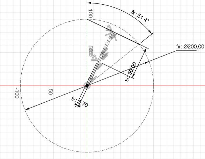
- Turned the construction gap rectangle into a solid rectangle
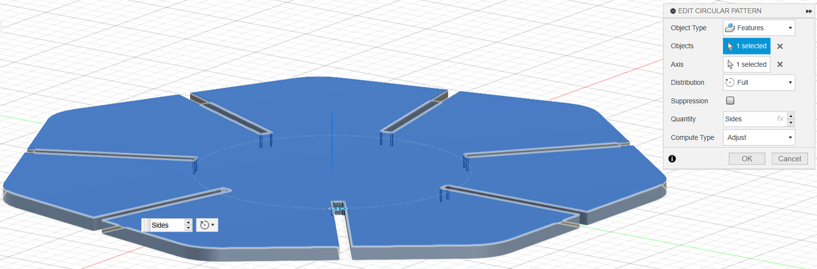
- Created a circular pattern from the side line and the gap lines. Determined the quantity of the pattern with the parameter for quantity of sizes.
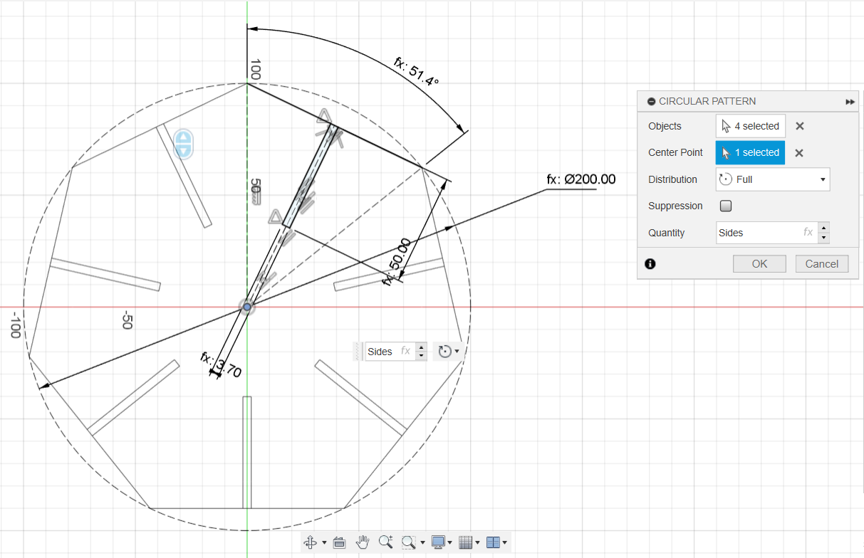
- Finished the sketch.
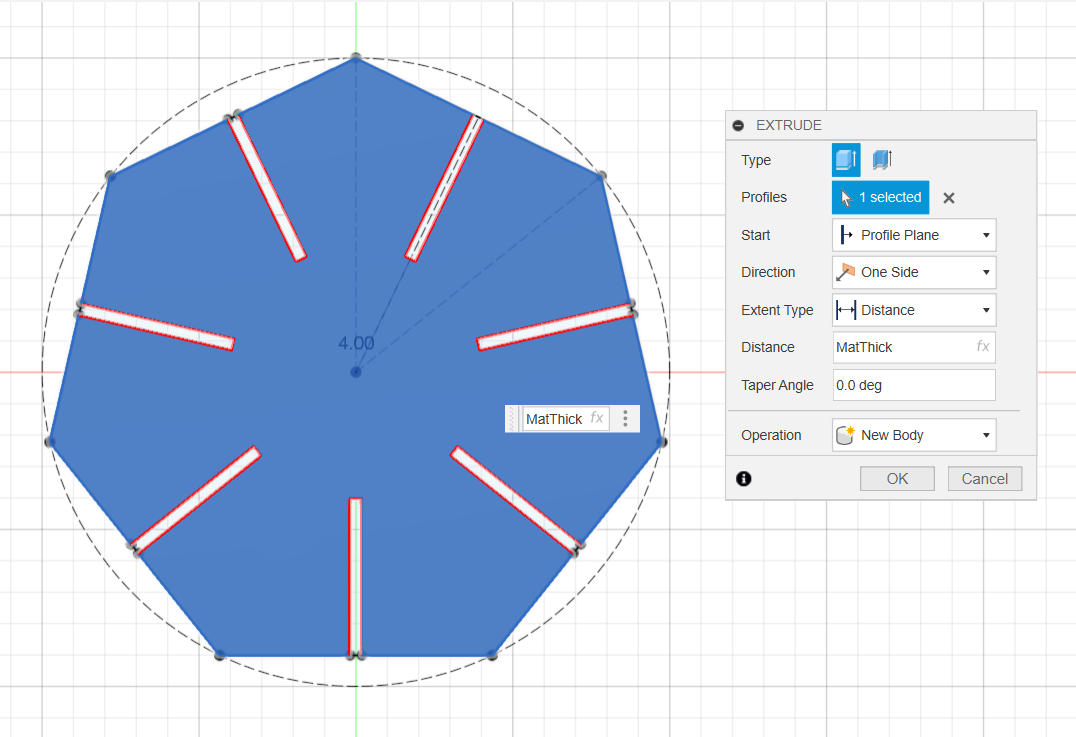
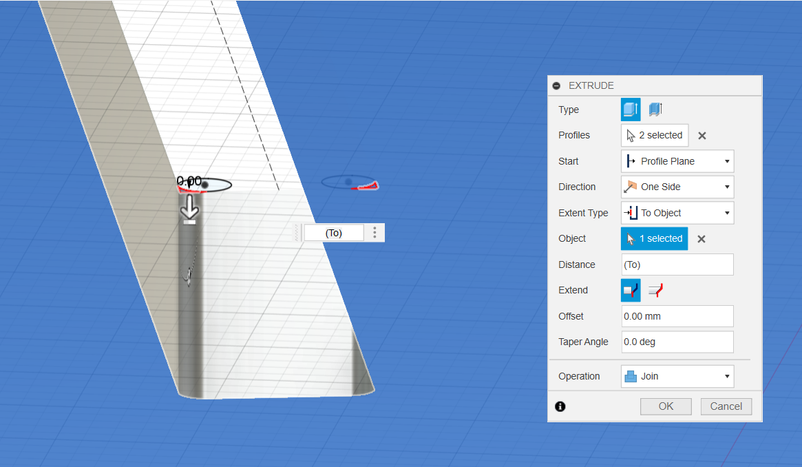
- Extruded the face of the sketch. Determined the length of the extrusion with the thickness parameter.
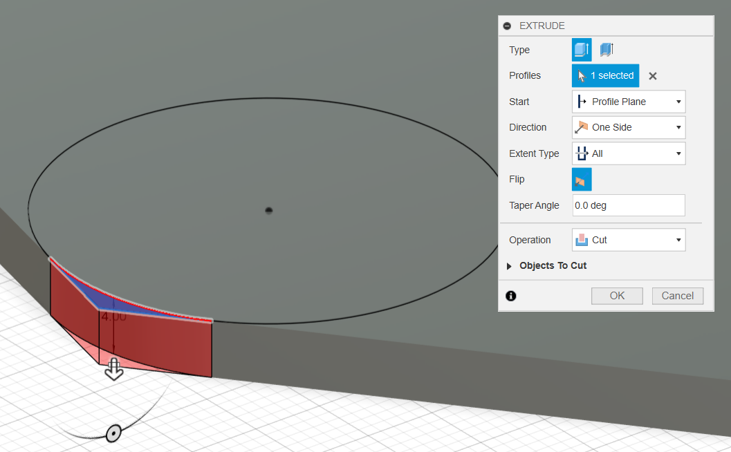
- Created the outer fillet on the shape:
- Created a sketch construction circle on the top face of the shape (without letting it snap to anything).
- Created a tangent constraint between the circle and two sides of the shape.
- Determined the size of the circle with our outer fillet parameter.
- Selected the area between the corner of both sides and the circle to create a cut extrusion, creating the fillet.
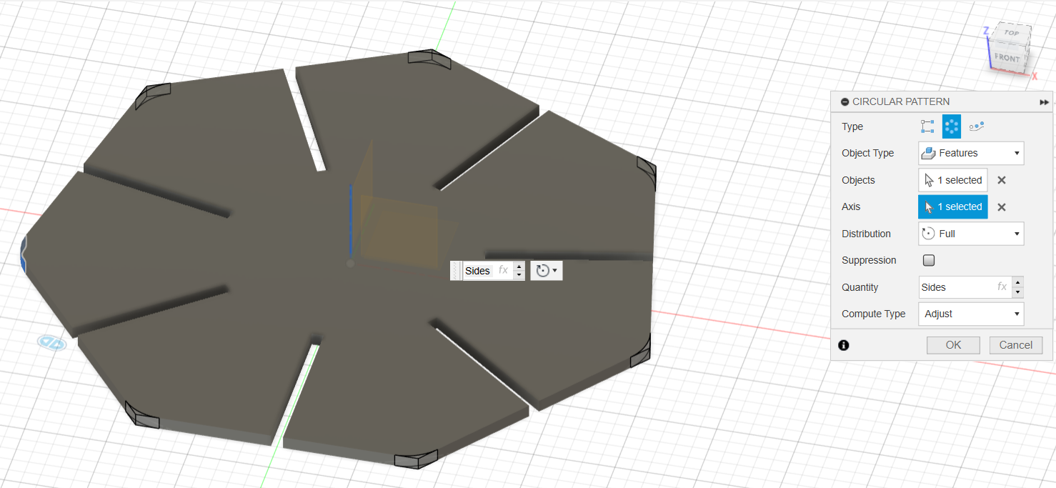
- Created a circular pattern from the cut extrusion. Determined the quantity of the pattern with the parameter for quantity of sizes.
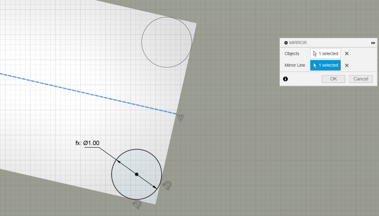
- Created the gap inner fillet:
- Drew a construction line from the center of the gap on the top face of the shape towards the outside. Then applied a parallel constraint on it with one of the gap's side lines.
- Drew a circle between the construction line and one of the gap's sides (without letting it snap to anything).
- Created a tangent constraint between the circle, the gap bottom line, and the gap side line.
- Created a mirror of the circle along the construction line across the center of the gap.
- Selected the area between the corner of both sides and the circles to create a cut extrusion, creating the fillet.
- Created a circular pattern from the cut extrusion. Determined the quantity of the pattern with the parameter for quantity of sizes.
My design file can be downloaded here.
Parametric Design with Grasshopper on Rhino
On Friday morning, Dani gave us an introductory class on Grasshopper with Rhino. He showed us the grasshopper primer and the Kangaroo plugin for physics modelling. Then, he did an example of how to use grasshopper for us to understand the data flow and key components. Afterwards, we did the following polygon array:
In order to achieve this, we:
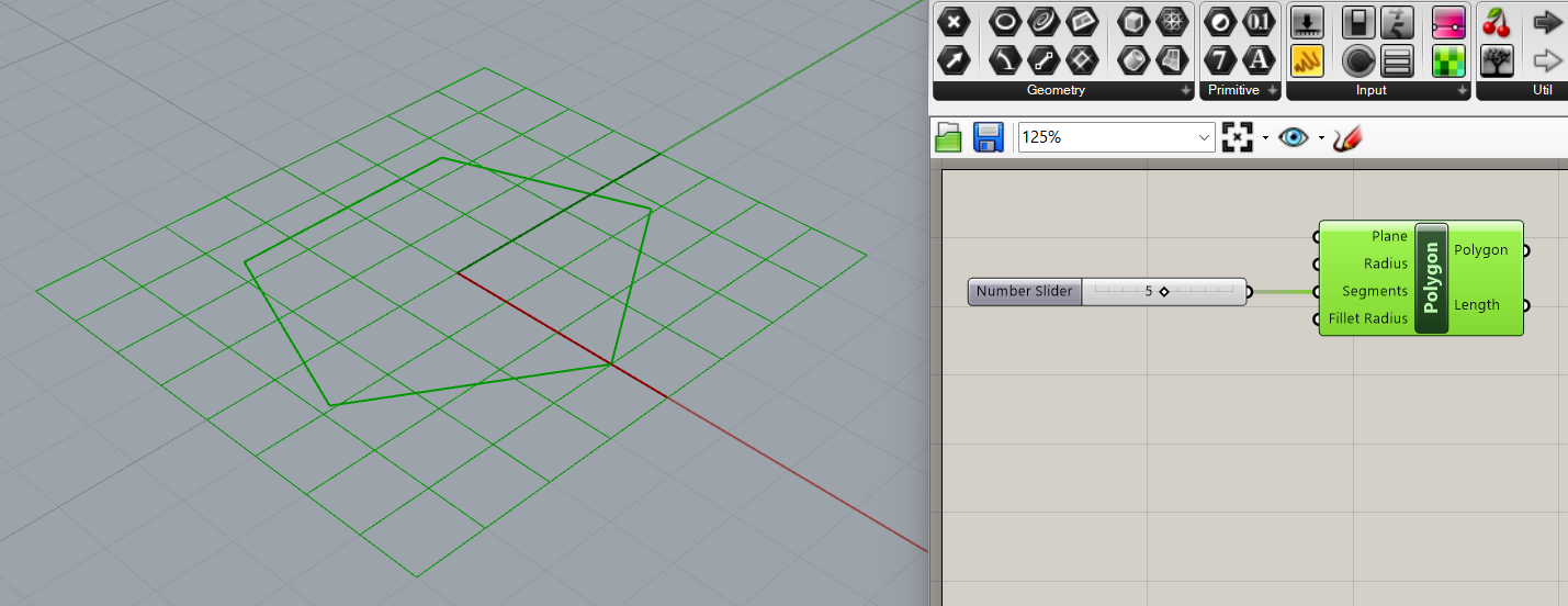
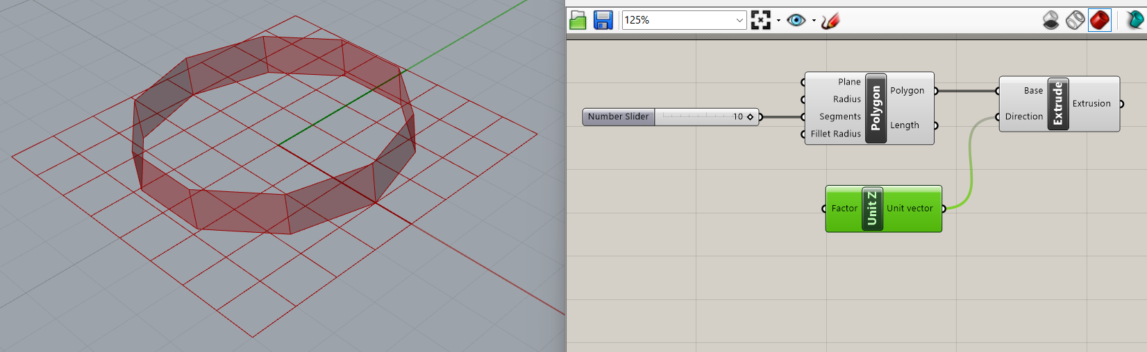
- Created a "polygon" parameter on the XY axis.
- Created a "number slider" parameter to determine the number of sides for the polygon.
- Wired the "number slider" parameter's output to the "segments" input on the "polygon" parameter.
- Created an "extrusion" parameter.
- Determined which shape to extrude (the polygon) by wiring the "polygon" output of the "polygon" parameter to the "base" input of the "extrusion" parameter.
- Created a "number slider" parameter.
- Created a "unit z" vector.
- Wired the "number slider" parameter's output to the "factor" input of the "unit z" vector.
- Wired the "unit vector" output of the "unit z" vector to the "direction" input of the "extrusion" parameter. This determined the distance by which we wanted to extrude on the Z axis.
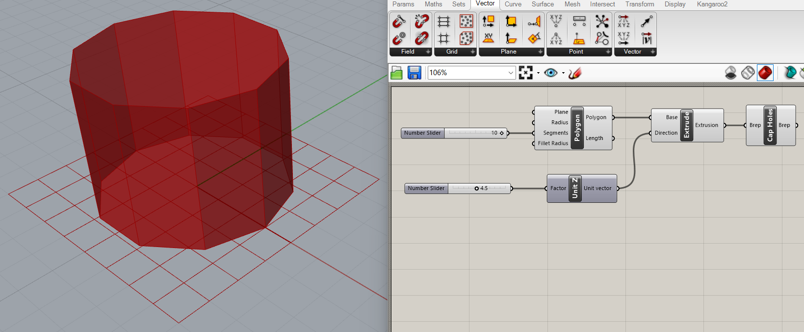
- Created a "cap holes" surface parameter.
- Wired the "extrusion" output of the "extrusion" parameter to the "brep" input of the "cap holes" parameter. This turned the extrusion into a boundary representation, so basically it turned it into a solid.
- Created a "rectangular array" geometry parameter.
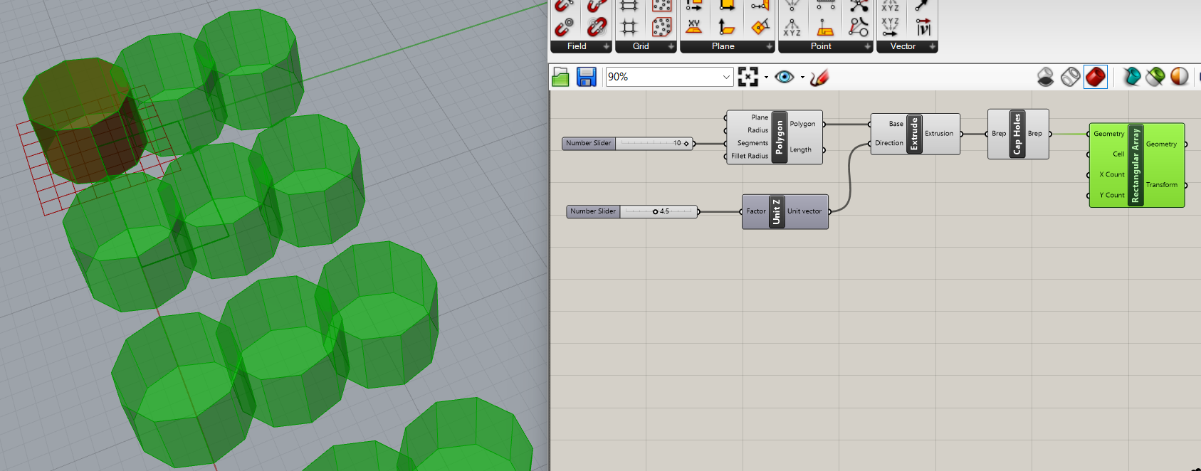
- Created a "number slider" parameter.
- I wanted my polygon array to be square, so I wired the "number slider" parameter's output to both the "x count" and "y count" inputs on the "rectangular array" parameter.
- Created a "rectangle" parameter to determine the spacing between objects in the array.
- Created a "number slider" parameter to determine the size of the rectangle for the spacing of objects.
- I wanted the spacing between the objects in my array to be even on both the X axis and the Y axis, so I wired the "number slider" parameter's output to both the "X size" and "Y size" inputs on the "rectangle" parameter.
- Wired the "rectangle" output from the "rectangle" parameter to the "cell" input on the "rectangular array" parameter.
- Created a point in Rhino.
- Created a "point" parameter.
- Linked the "point" parameter to the point in Rhino.
- Created a "brep closest point" parameter.
- Wired the "point" parameter's output to the "point" input on the "brep closest point" parameter.
- Wired the "geometry" output of the "rectangular array" parameter to the "brep" input on the "brep closest point" parameter.
- Created a "scale non uniform" parameter.
- Wired the "geometry" output of the "rectangular array" parameter to the "geometry" input of the "scale non uniform" parameter.
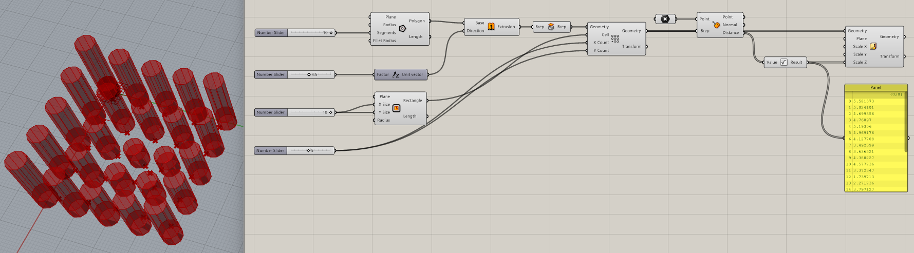
- Wired the "distance" output of the "brep closest point" parameter to the "scale Z" input of the "scale non uniform" parameter. This randomly extruded the array's objects across the Z axis.
- Created a "panel" parameter
- Wired the "distance" output of the "brep closest point" parameter to the "panel" parameter's input to be able to see the distance each object was extruded by the "scale non uniform" parameter.
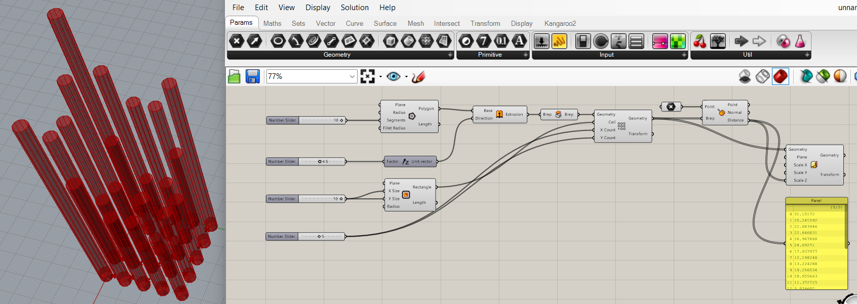
- Created a "square root" parameter.
- Disconnected the "distance" output of the "brep closest point" parameter from the "scale Z" input of the "scale non uniform" parameter.
- Disconnected the "distance" output of the "brep closest point" parameter to the "panel" parameter's input.
- Wired the "distance" output of the "brep closest point" parameter to the "value" input of the "square root" parameter.
- Wired the "result" output of the "square root" parameter to the "scale Z" input of the "scale non uniform" parameter.
- Wired the "result" output of the "square root" parameter to the "panel" parameter's input to be able to see the distance each object was extruded by the "scale non uniform" parameter after being adjusted by the "square root" parameter.
My grasshopper design file can be downloaded here. My rhino design file can be downloaded here.
Assignments
1. Do the lab's safety training as a group
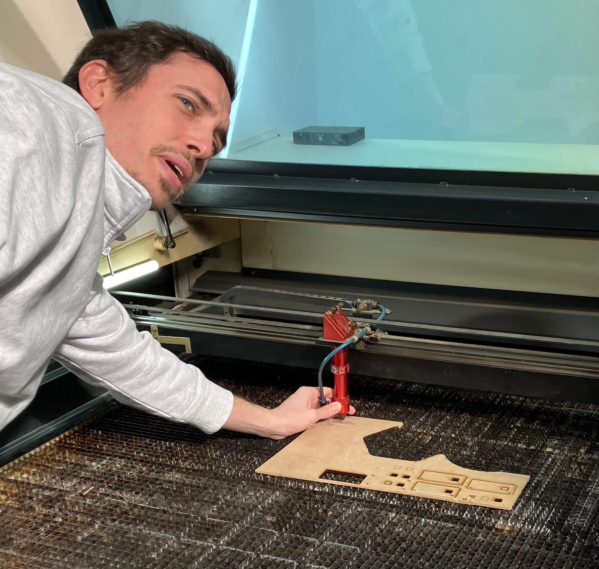
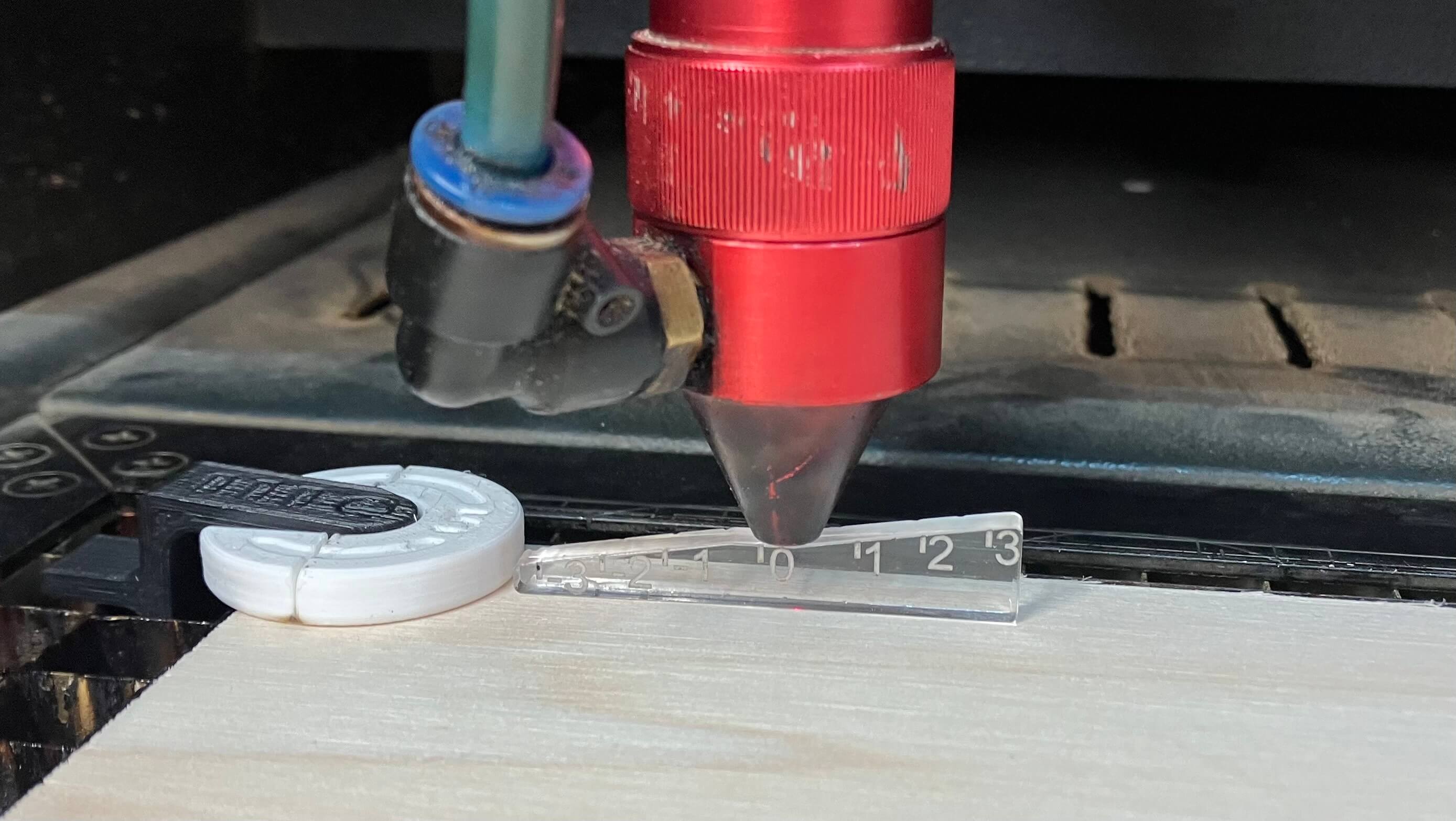
Josep showed us the 4 laser cutters we have at the lab. He opened the inside of one of them for us to see and better understand how they worked. Then, he showed us the basic workflow for using them and pointed out the general safety pre-checks. He also explained what processes to follow in case things go wrong. Below is an image of Josep teaching us how to use the tool to callibrate the Rayjet 500's focus.
2. As a group, characterize your lasercutter's focus, power, speed, rate, kerf, joint clearance and types. Document your work to the group work page and reflect on your individual page what you learned.
Luckily for us, each laser cutter at the lab has a tool to characterize the focus of the laser. They all essentially consist of pieces that determine a specific height between the laser's lens and the material.
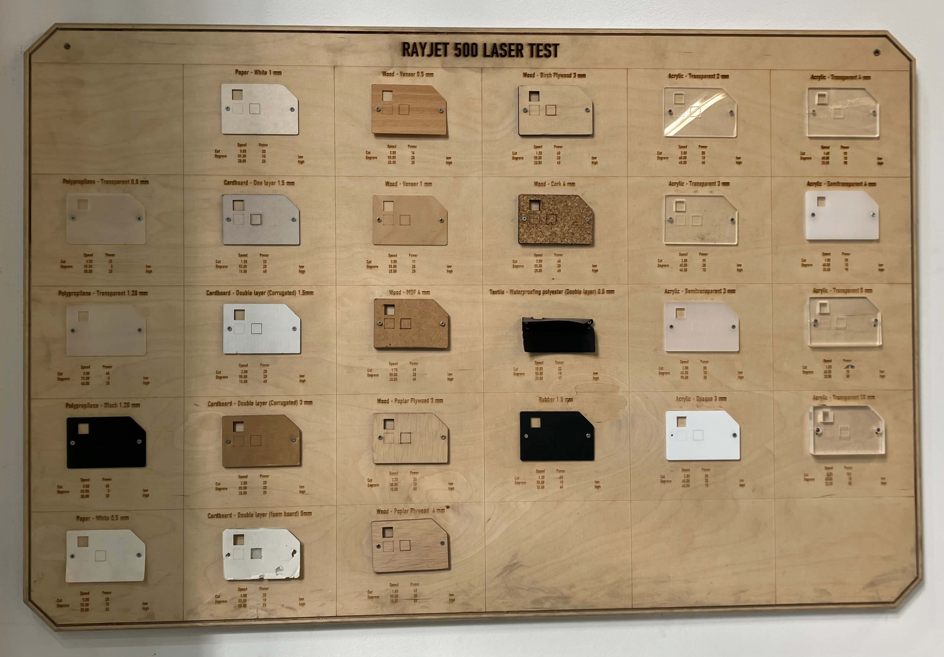
We also have reference tables available for every material, per machine, where we can consult the suggested power and speed. Below is an immage of the table for the Rayjet 500, which is also used for the Rayjet 400, which is the machine we used for the assignment.
This machine has an automatic rate, so we couldn't do anything to characterize it.
For the kerf characterization, we designed a kerf tester for cardboard, for plywood, for acrylic, and cut them on the machine. We started by measuring the material. Then we designed the tester around each material's thickness. We cut the testers using the suggested references. After we cut, we realized our measurements were too optimistic, so we re-designed.
The documentation of the work we did for the kerf tester can be found here.
3. Design, lasercut, and document a parametric construction kit, accounting for the lasercutter kerf, which can be assembled in multiple ways, and for extra credit include elements that aren't flat
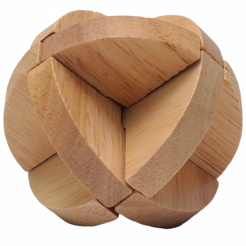
As soon as Neil explained this assignment, I thought about doing a Rubik's Cube. I did a lot of brainstorming and research about it and ended up going down a rabbithole on interlocking puzzles, which led to me deciding to do a Luban Lock Ball instead. While it was easier and faster to design, and actually feasible to laser cut, it wasn't exactly able to be assembled in many different ways. So although I did fabricate it, I also did an assembly of planetary gears to fulfill this week's assignment requirements.
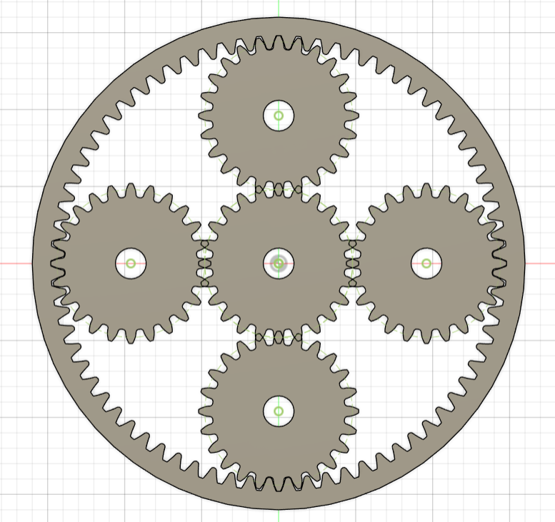
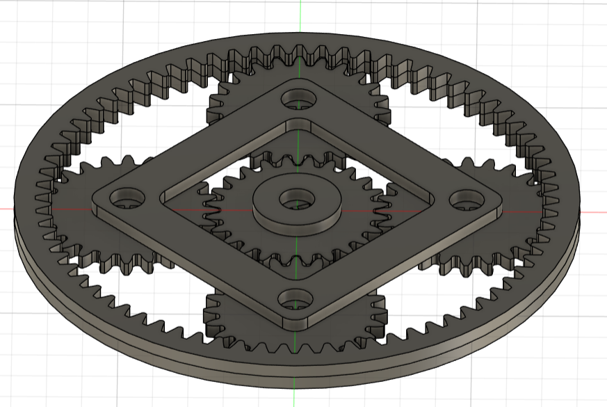
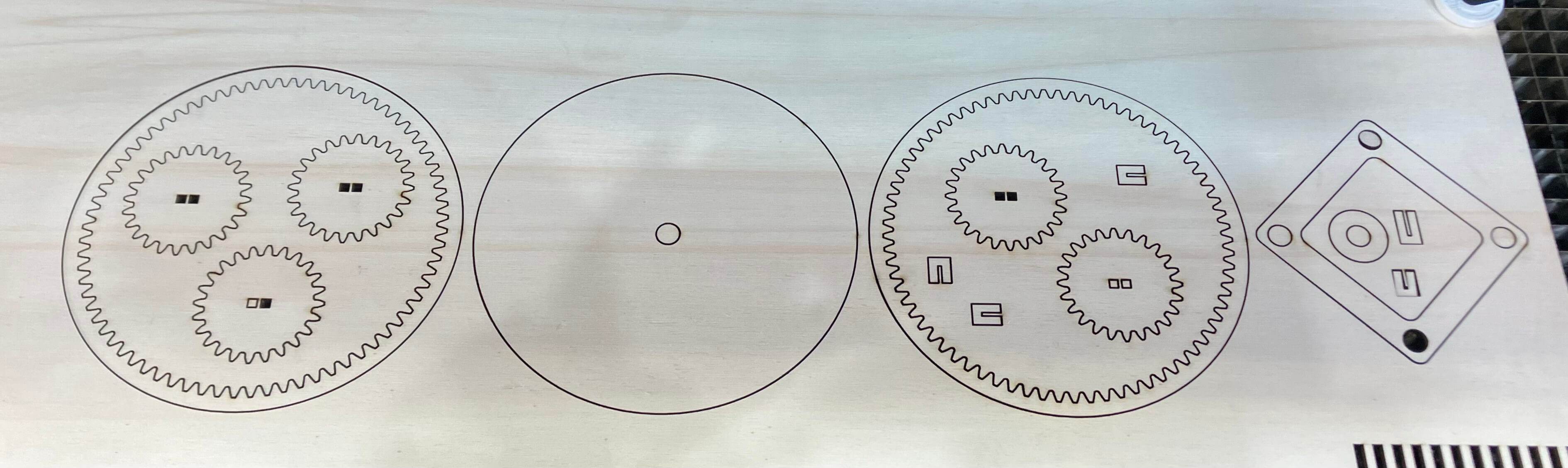
Planetary Gears
Parametric Design
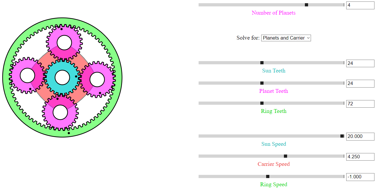
- Decided I wanted to have 4 planet gears and a sun gear which were all the same size so that they could be exchangeable.
- Used this planetary gear simulator tool to determine how many teeth each one of my gears had to have.
- Watched this youtube tutorial to start creating my design in Fusion.
- Created a new file.
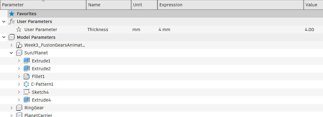
- Created the "thickness"=4mm parameter.
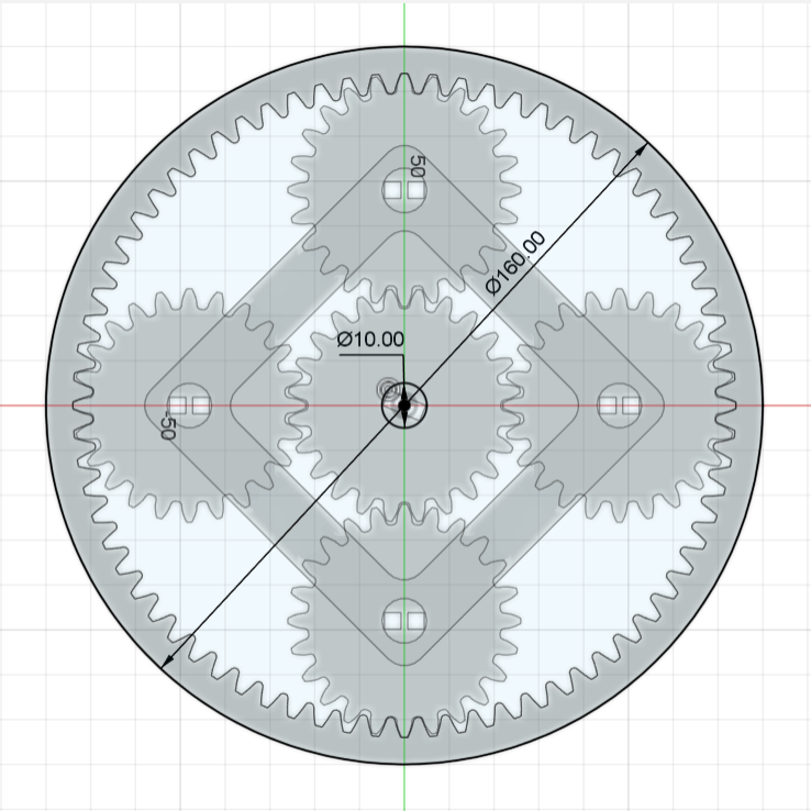
- Ran the SpurGear C++ Sample Add-in to create a new component for the ring gear.
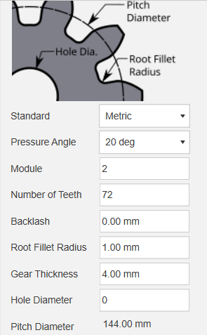
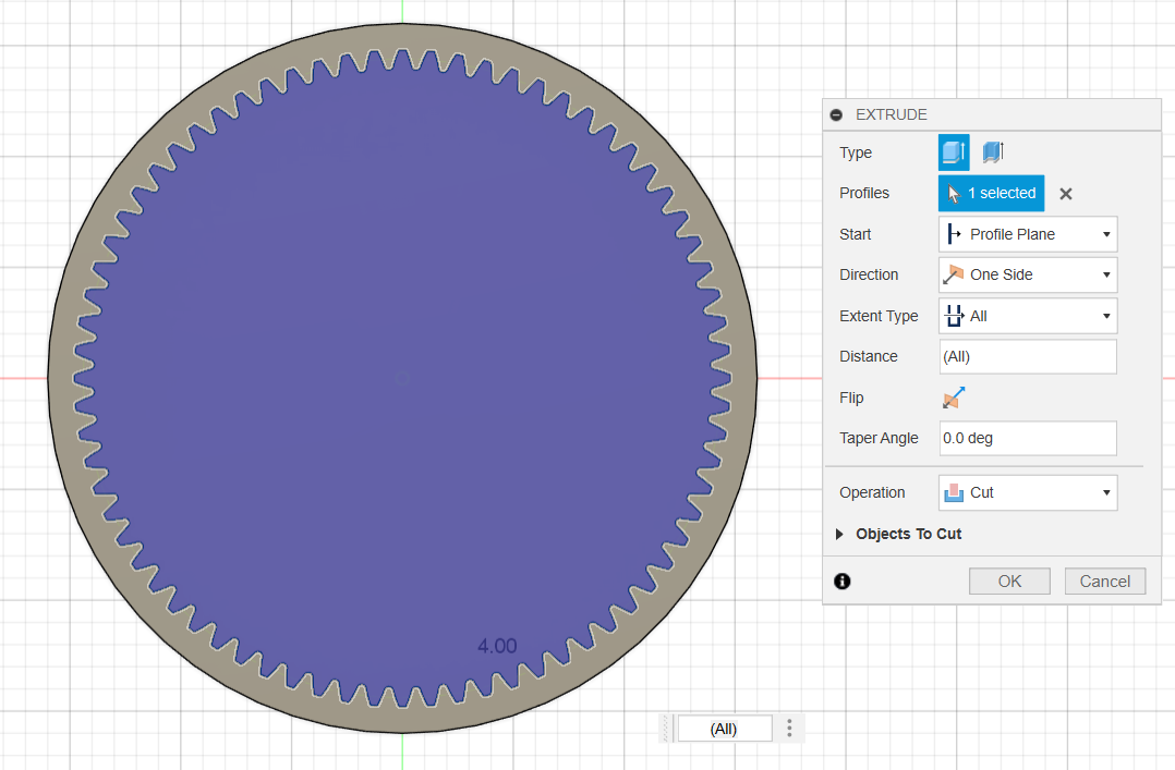
- Created a cylinder in this component with a height equal to the "thickness" parameter.
- Cut extruded the ring gear from the cylinder to have the body for the ring gear that will actually be used.
- Ran the SpurGear C++ Sample Add-in to create a new component for the sun/planets gear.
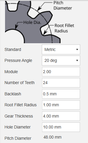
- Selected the sun/planets gear component and moved it 48mm across the X and Y axis while creating a copy (did this 4 times). Any changes done on the center (original) gear get replicated into the other 4 copies.
- Modified the center of the sun/planet gears so that instead of the original 10mm circle, there was two openings for the joints.
- Duplicated the ring gear into a new component for the middle layer of the assembly.
- Created a new component for the gear carrier.
- Created a sketch on the gear carrier component.
- Used the planet gears center hole sketches as reference points, and created lines joining them through the inside and outside.
- Created a 5mm fillet through the center lines.
- Added a 3-point rectangle 5mm outside the carrier structure.
- Created a 5mm fillet on the outer rectangle of the component.
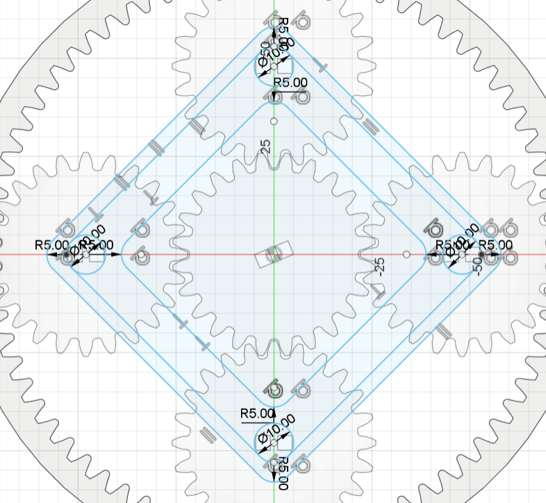
- Extruded a surface from the sketch with a height equal to the "thickness" parameter to create the body for the gear carrier.
- Created a new component for the base of the sun gear.
- Created a sketch.
- Created a 10mm circle.
- Created a 25mm circle around the previously created circle.
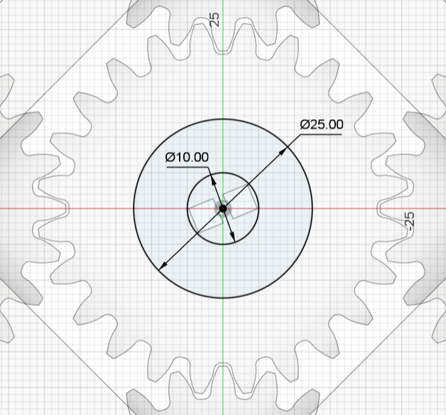
- Extruded the area between the circles with a height equal to the "thickness" parameter.
- Created a new component for the assembly's base.
- Created a sketch.
- Created a 10mm circle.
- Created a circle with the same diameter as the ring gear's outer diameter.
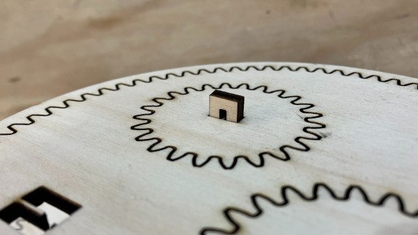
- Created a sketch on a new component for the joints that hold the gears into the carrier and the assembly.
- Extruded the joints with a height equal to the "thickness" parameter and copied the component 5 times.
- Modified one of the joints, the one for the sun gear, to be 4mm longer in height than the rest of the joints, so that it goes all the way down into the assembly's base.
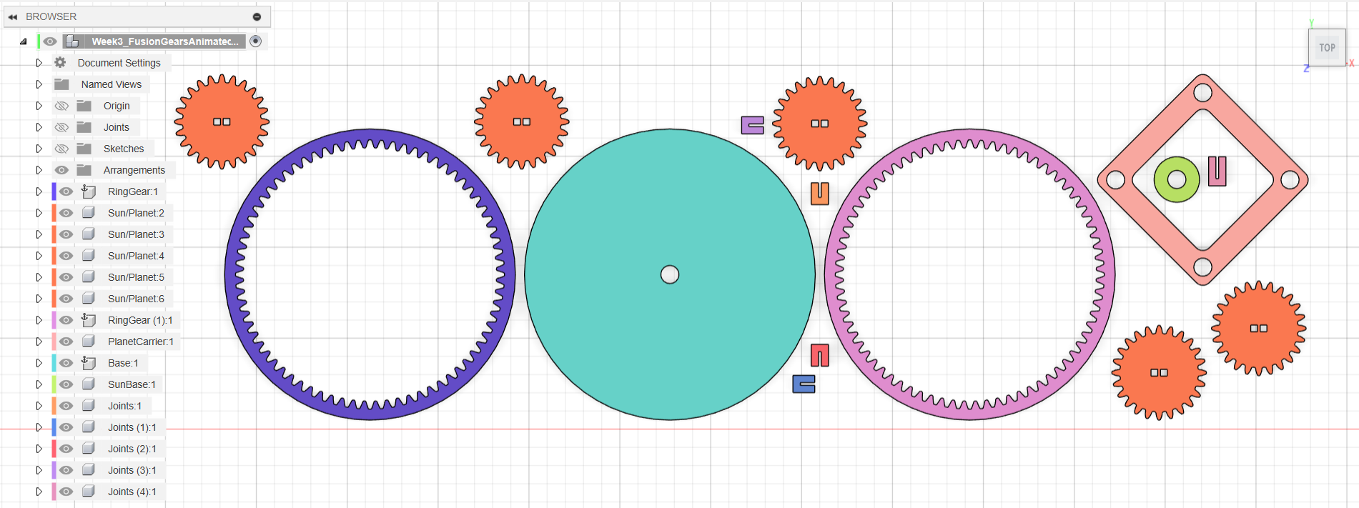
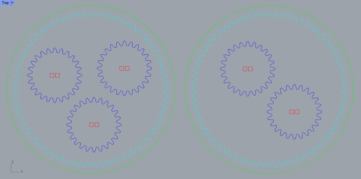
- Created an arrangement to have all the pieces layed out for cutting.
- Created a sketch.
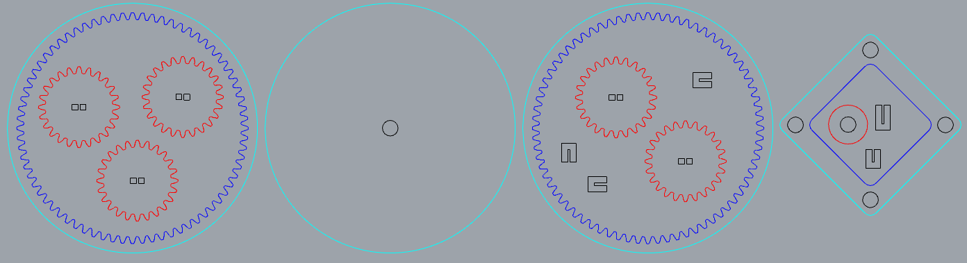
- Created a projection of all the pieces on the sketch and exported the DXF file.
- Opened the DXF file in Rhino and modified it for cutting.
The Fusion file can be found here. The Rhino file can be found here.
Press-fit Construction
- Placed my sheet of 4mm plywood on the Rayjet 500 machine and clamped it down.
- Focused the laser with its respective tool.
- Imported the file from our local cloud into the cutter's file manager.
- Placed the job on the manager's surface.
- Moved the laser along the length and width of the job to ensure my placement was ideal along the material.
- Adjusted the laser's parameters to cut with 45 on power and 1.8 on speed at every process.
- Turned the air supply on and closed the lid.
- Sent the file and cut the pieces.
- Opened the lid, shut the air supply off, and extracted the pieces. After taking them all out, I noticed the gears had not been cut all the way through.
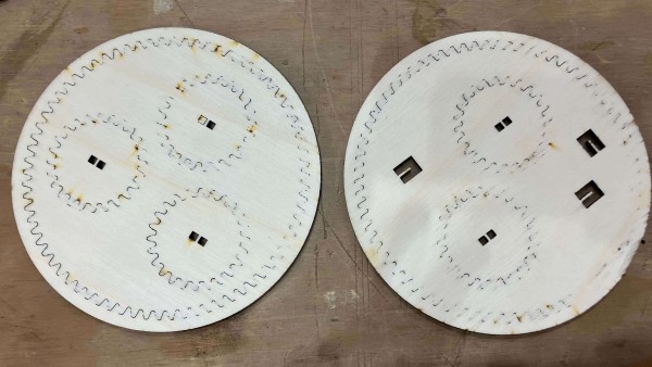
- Since my pieces were already out, I couldn't just re-run the machine. So instead, I adjusted the design file so that I could start a new job printing just what I needed. I changed the processes to be one layer deeper to see if that helped.
- Placed the new job on the file manager's surface.
- Moved the laser along the length and width of the new job to ensure my placement was ideal along the material.
- Adjusted the laser's parameters to cut with 50 on power and 1.8 on speed.
- Turned the air supply on and closed the lid.
- Sent the file and cut the pieces.
- Tested the joints on the improperly cut gears while the new ones were getting cut and they worked well! The group assignment taught me well the kerf I could expect from this machine.
- Once the laser cutter finished I opened the lid, shut the air supply off, and succesfully extracted all the pieces.
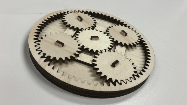
The assembly was a success. Everything fit and the gears moved well. However, I knew I could improve it. Since the base layer and the outer rings weren't attached, you had to hold them in place if you wanted to move the gears. For this reason, I designed some clamps. I also re-designed the joints to make them stronger and more aesthetically pleasing. I also made the sun gear's joint longer on top to make it easier to rotate the gears.
So, I:
- Created a new file on Fusion.
- Copied the joints for the planetary gears and sun gear from the original file and pasted them as new.
- Created a 1mm chamfer on the inner openings of the joints.
- Created a 3.8 fillet on the top sides of the joints.
- Went back to the original file and measured the distance between the outer diameter of the ring gear and the top of the teeth. Chose to do the clamps half of that length
- Created a new component for the clamps.
- Created a sketch based on the dimensions from the assembly.
- Extruded the clamps 4mm.
- Copied and pasted the planet gear joint 3 times and the clamps 2 times.
- Created a new sketch.
- Projected all the geometries onto the sketch and saved the DXF file.
- Opened the DXF file on Fusion and prepared it for cutting.
- Uploaded the file into our local cloud.
- Placed a new sheet of 4mm plywood on the Rayjet 500 machine and clamped it down.
- Focused the laser with its respective tool.
- Imported the file from our local cloud into the cutter's file manager.
- Placed the job on the manager's surface.
- Moved the laser along the length and width of the job to ensure my placement was ideal along the material.
- Adjusted the laser's parameters to cut with 50 on power and 1.8 on speed at every process.
- Turned the air supply on and closed the lid.
- Sent the file and cut the pieces.
The Rhino file for the second cut can be found here. The Fusion file for the iterations can be found here. The Rhino file for the iterations can be found here.
Luban Lock Ball Puzzle
Parametric Design
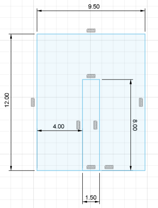
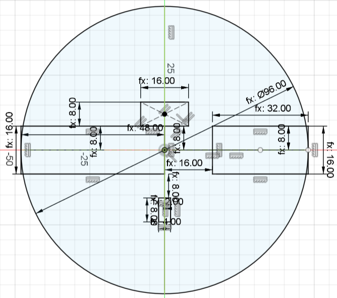
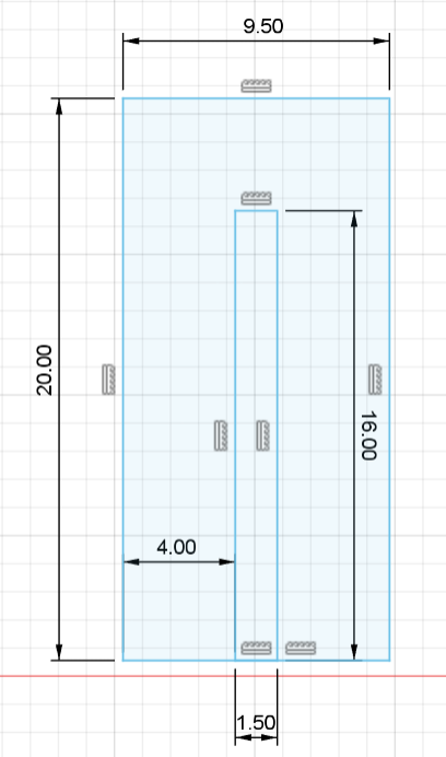
I have never held a Luban Lock Ball Puzzle and had no idea what size they are. So, I did a lot of research and found this very useful blogpost of someone who had already gone on the journey I was about to go on. I used their "Luben Ball" pdf available here as the starting point for my construction kit. I got to work with the following image as my point of reference (my own notes in blue describe the final design):
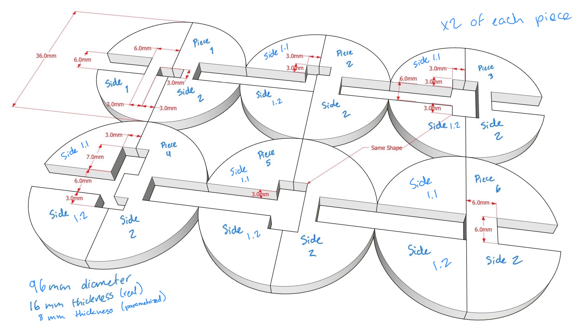
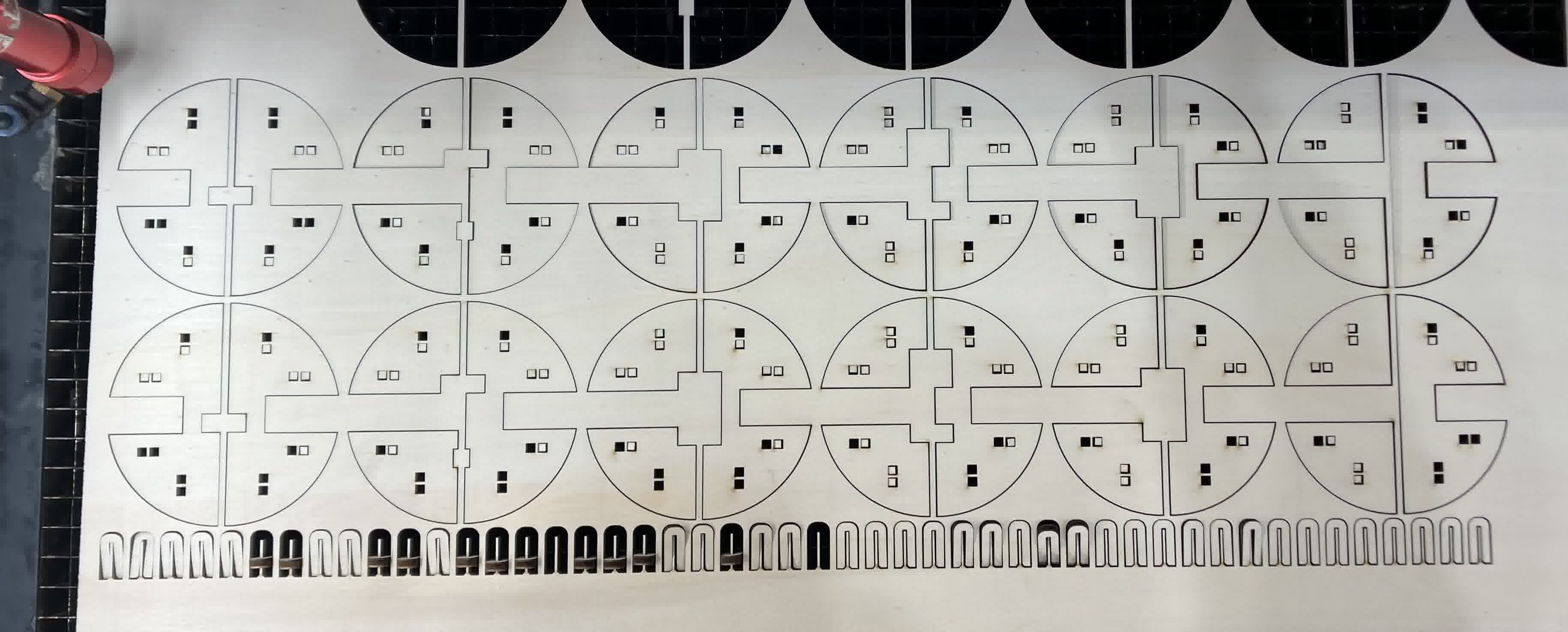
The idea was to create each piece separately. Starting with the same dimensions as the reference, and then parametrically changing them to be what I wanted. I chose the dimensions so that I could print each piece twice on 4mm plywood, and then press-fit the duplicates and sides together to make a single 16mm thick piece.
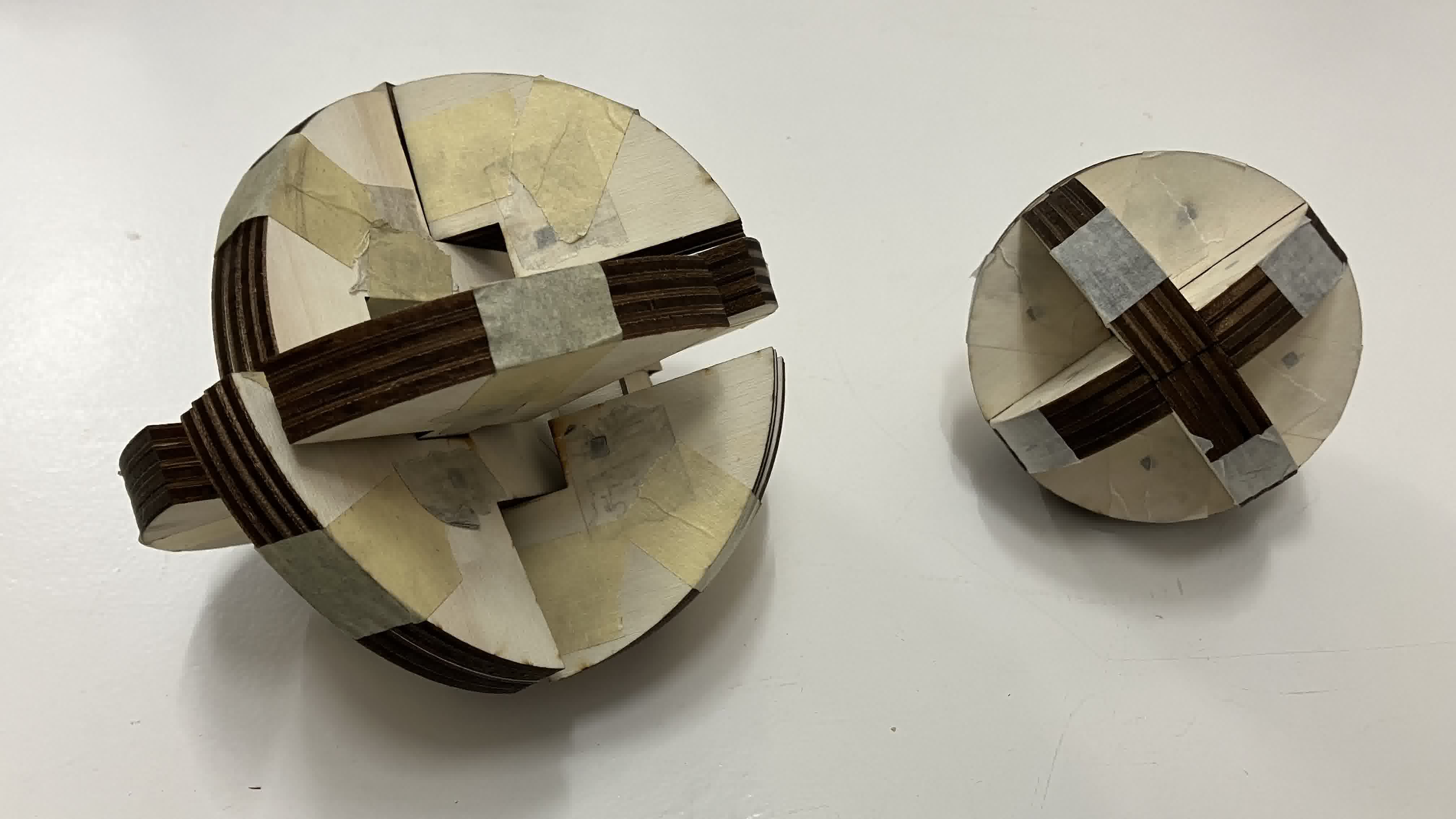
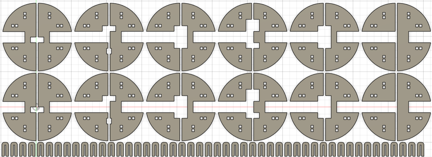
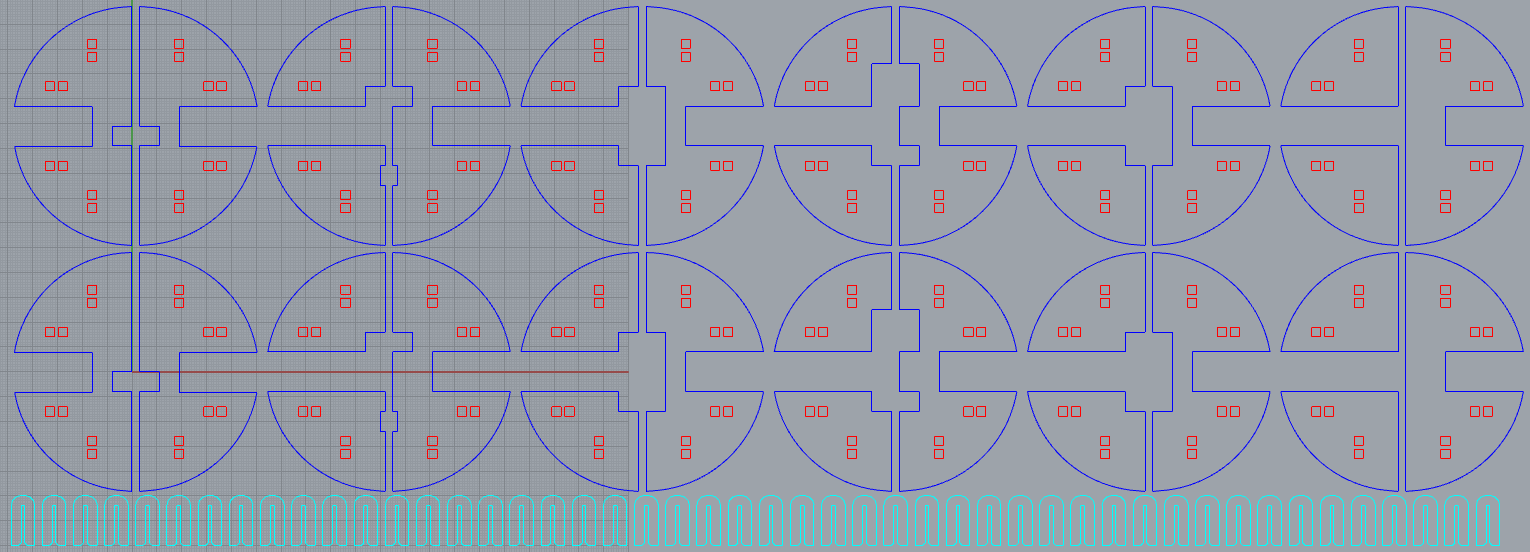
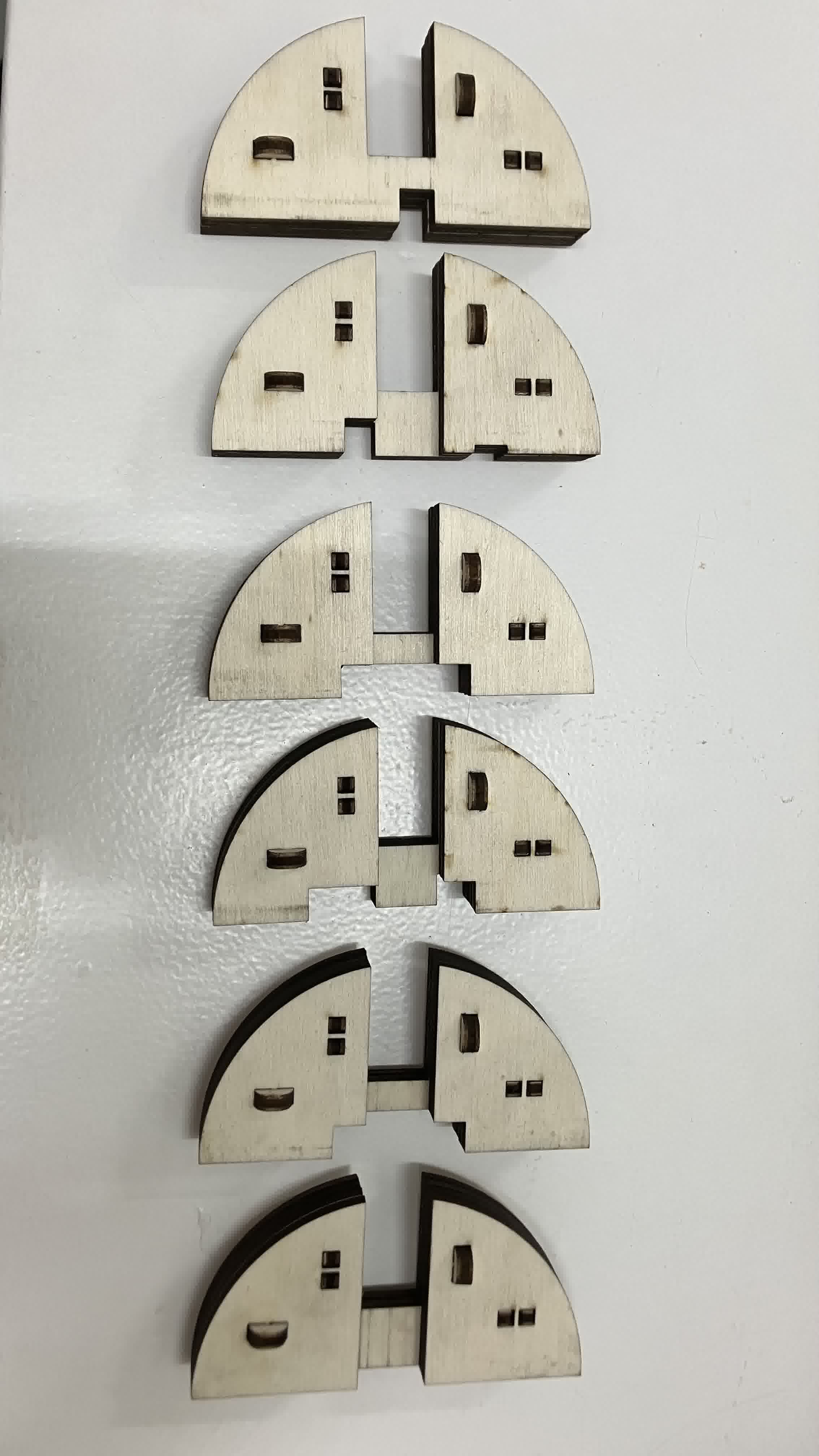
I was half-asleep doing the first version of the design and I got the ratio for some dimensions wrong, so my first cut was a failure. I also made the joint holes slightly too big, so the locking pins slid out in most pieces. I then re-parametrized the shapes so that the puzzle would lock, and also changed the size and location of the joint holes so that the structure was better supported. However, I made the joint holes too small this time, so for the puzzle to lock I had to tape the pieces together. Below is a side by side comparison of my first two cuts.
After two failed attempts, I re-designed the joints so that instead of being single pins, they would be actual joints. I had originally planned to do this modification for the second cut but I didn't have time before my booked slot on the cutter.
My final working design went like this:
For each piece I:
- Opened a new file for each piece.
- Created a new component and named it according to which piece I was working on.
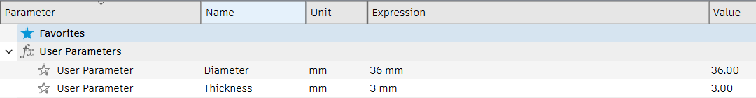
- Established the parameters "diameter"=36mm and "thickness"=3mm.
- Created a sketch.
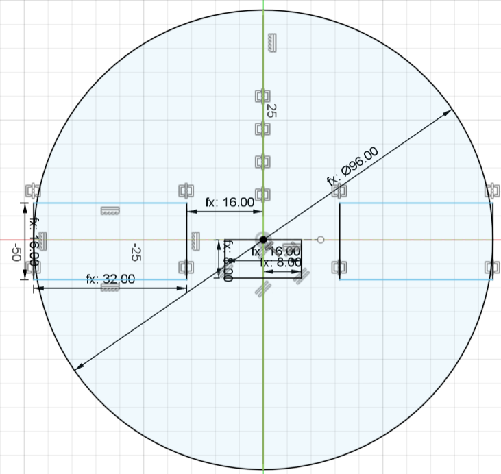
- Created a center diameter circle from the point of origin with the diameter being the "diameter" parameter.
- Created construction lines through the middle of the circle along the X and Y axis.
- Sketched each piece following the reference. If the reference's dimension was 3mm, my dimension was ="thickness" parameter. If the reference's dimension was 6mm, my dimension was ="thickness" parameter * 2. Every other constraint or dimension was arithmetically derived from thes ebasic principles.
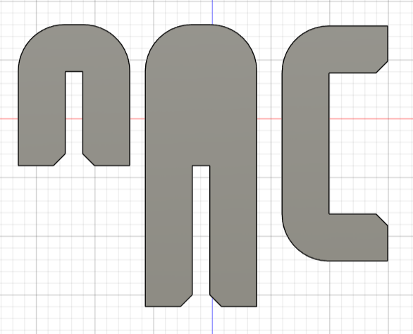
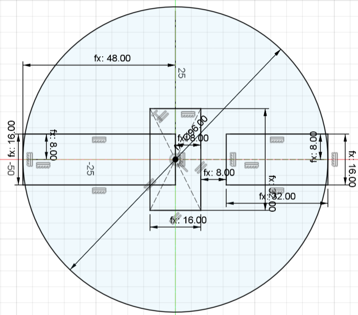
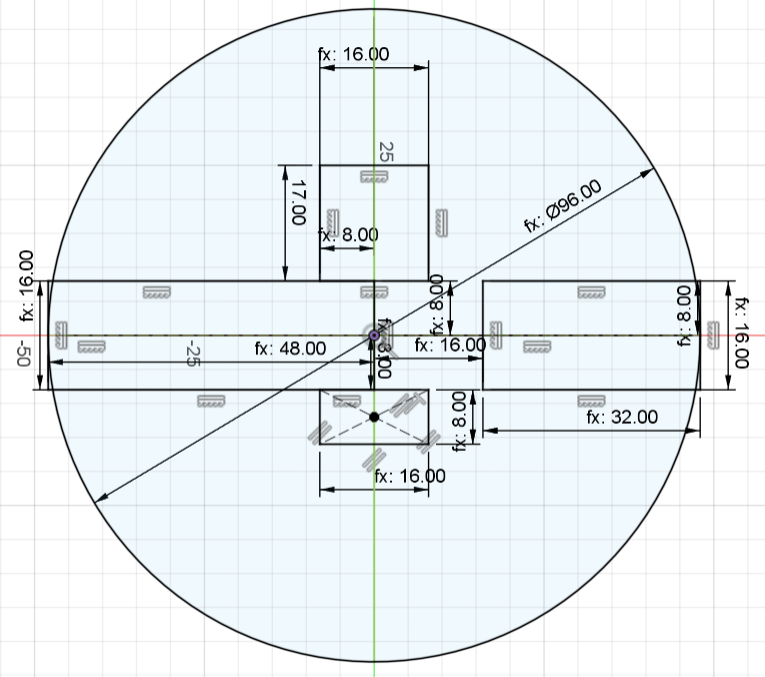
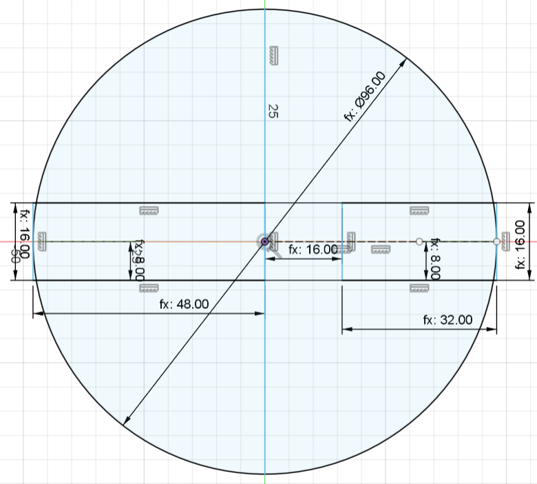
Each piece's sketch ended up looking like this:
Piece 1
Piece 2
Pieces 3 and 5
Piece 4
Piece 6
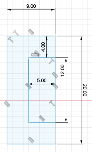
Then, I created the holes for the joints:
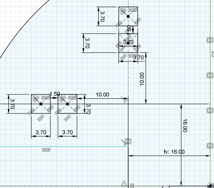
- Created a construction line from the center x-axis to the edge of the circle.
- Created a 16mm distance between the previously created line and the center y-axis.
- Created a construction line from the center y-axis to the edge of the circle.
- Created a 16mm distance between the previously created line and the center x-axis.
- Created a 3.7mmx3.7mm center rectangle on the first construction line.
- Created a 10mm distance between the previously created rectangle and the center y-axis.
- Created another 3.7mmx3.7mm center rectangle on the first construction line.
- Created a 1.5mm distance between both rectangles.
- Created a 3.7mmx3.7mm center rectangle on the second construction line.
- Created a 10mm distance between the previously created rectangle and the center x-axis.
- Created another 3.7mmx3.7mm center rectangle on the second construction line.
- Created a 1.5mm distance between both rectangles.
- Mirrored all 4 rectangles across the y-axis.
- Mirrored all 8 rectangles across the x-axis.
After each sketch was finished, I extruded each side of the piece as a new body with a height = "thickness" parameter.
Once I was done with all the pieces, I created the joint pieces in a new file. I essentially copied the final joints from my planetary gears assembly (with fillets and chamfers on the extruded body), I just changed the length to fit this design and extruded the object with this design's "thickness" parameter.
Then, I:
- Created a new file to lay down the whole assembly.
- Opened all the files.
- Copied each piece's component from their original file.
- Pasted each piece's component as new twice on the assembly file.
- Separated the duplicate pieces by 3mm across the X axis.
- Copied the joint component on the joints file.
- Pasted the joint component as new on the assembly file.
- Separated the joints by 3mm underneath the pieces.
Then, I:
- Created a sketch on the file.
- Projected all the bodies into the sketch.
- Exported the sketch as a .DXF file.
- Opened the .DXF file on Rhino and edited the shapes to be colorized and joined for the cutting.
- Saved the Rhino file and uploaded it to the FabCloud to send to the printer.
The way I did all the pieces in different files and then created a new file to lay them all out, I now realize, was definitely not the most efficient way to work. I should have done what I then did for the planetary gears. I think that would have reduced my working time by a lot. I also thinnk instead of mirroring the rectangles for the joint holes, I could have done circular arrays and that would have also saved me some time. But this is how you learn! Luckily I applied some of these learnings into the planetary gears assembly and that reduced my working time and allowed me to fine tune more details.
The Fusion file can be found here. The Rhino file can be found here.
Press-fit Construction
- Placed my sheet of 4mm plywood on the Rayjet 500 machine and clamped it down.
- Focused the laser with its respective tool.
- Imported the file from our local cloud into the cutter's file manager.
- Placed the job on the manager's surface.
- Moved the laser along the length and width of the job to ensure my placement was ideal along the material.
- Adjusted the laser's parameters to cut with 50 on power and 1.8 on speed at every process.
- Turned the air supply on and closed the lid.
- Sent the file and cut the pieces.
- Opened the lid, shut the air supply off, and extracted the pieces.
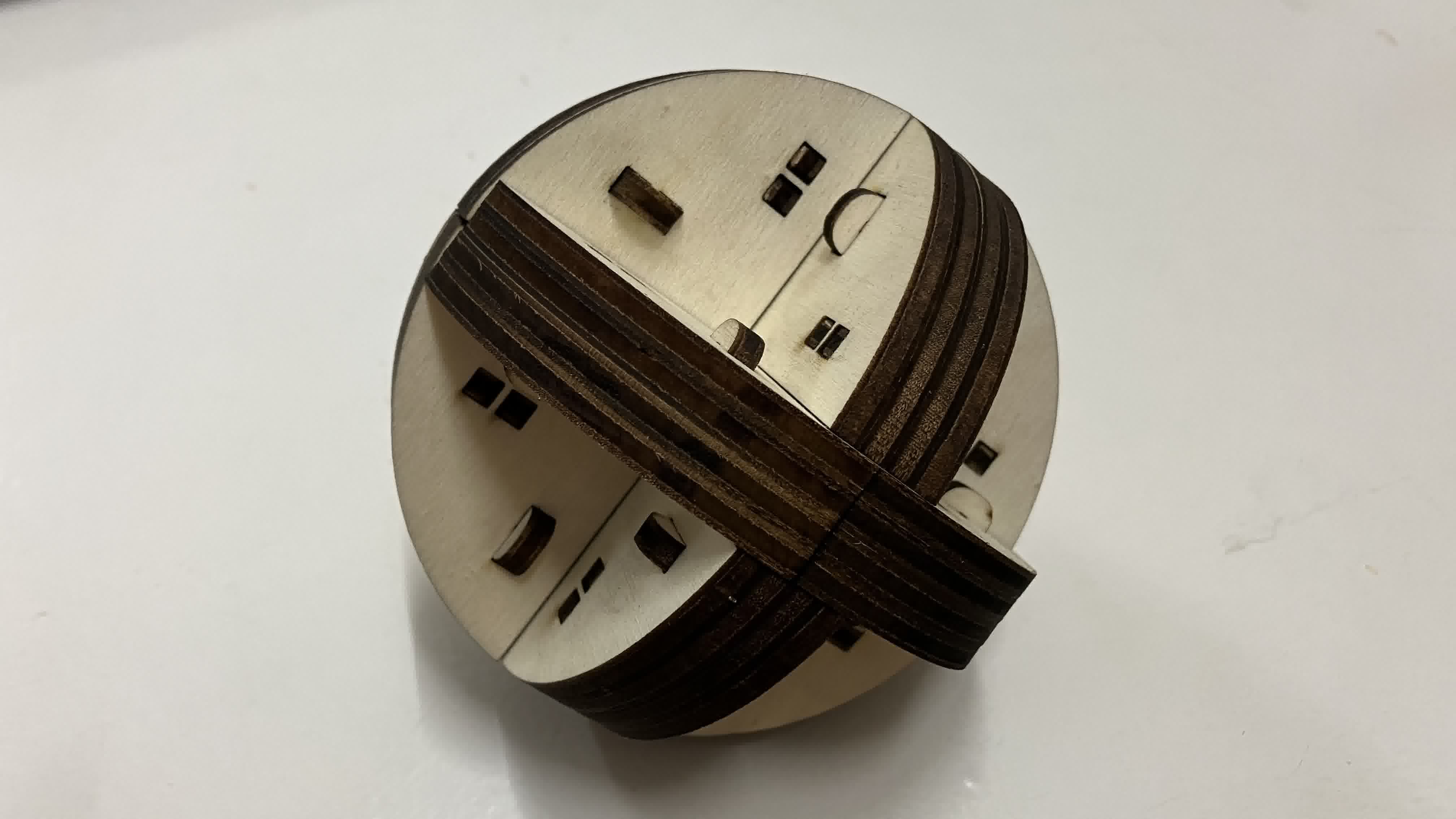
After I extracted the pieces, I joined all the layers with the joints to make the individual pieces.
Then I followed these instructions, which I found in the original blogpost I followed, to assemble the puzzle. In the end, it looked like this:
4. Cut something on the vinylcutter

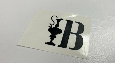
- Downloaded the Silhouette Studio software to drive the cutter.
- Downloaded the image I wanted to print, which is the logo for the 37th America's Cup (seen above).
- Imported the logo into Inkscape.
- Traced the bitmap of the image using the edge detection mode.
- Removed the original image.
- Exported the trace as an SVG file.
- Opened the SVG file in Silhouette Studio.
- Connected the computer to the cutter.
- Loaded my vinyl piece into the cutter, making sure it was inside the rollers that determine the material's width.
- The cutter detected the size of my material and adjusted its blade's depth accordingly (automatically).
- Sent the file and cut the logo.