Week 2
Computer Aided Design
Week Outline
- Wednesday: First Global Review. Global Lecture on Computer Aided Design.
- Thursday: Local Class on 2D and 3D Modelling, Rhino, Inkscape, and TinkerCAD.
- Friday: Local Class on OpenSCAD, Fusion, and Blender. I finished the LEGO exercise and caught up with my weekly documentation.
- Tuesday: I finished my weekly assignment.
- Wednesday: I caught up with the documentation for the weekly assignment. Global Review.
Using CAD software is like speaking a language. This week we focused on finding what language we feel more comfortably speaking in by trying to learn the same words in many different ones.
Global Class
On this week's global class, Neil gave a very basic introduction to what 2D and 3D modelling are. He explained the basics of how they worked. For 2D Design, he talked about raster and vector images, booleans, and constraints. For 3D design, he talked about the types of representations (boundary, function, volume), the types of design (imperative, declarative, generative), and the basic actions. He gave us some tips and tricks for general CAD modelling and showed us a lot of different softwares we can use. He also talked about interchange formats for our CAD files.
Local Classes
Introduction to 2D and 3D Modelling
Daniel started our local classes this week by going more in depth into what Neil covered in the global class. He talked about the difference between vectors and pixels in 2D and the difference between mesh and NURBS in 3D. He also gave us some modelling strategies.
The LEGO Exercise
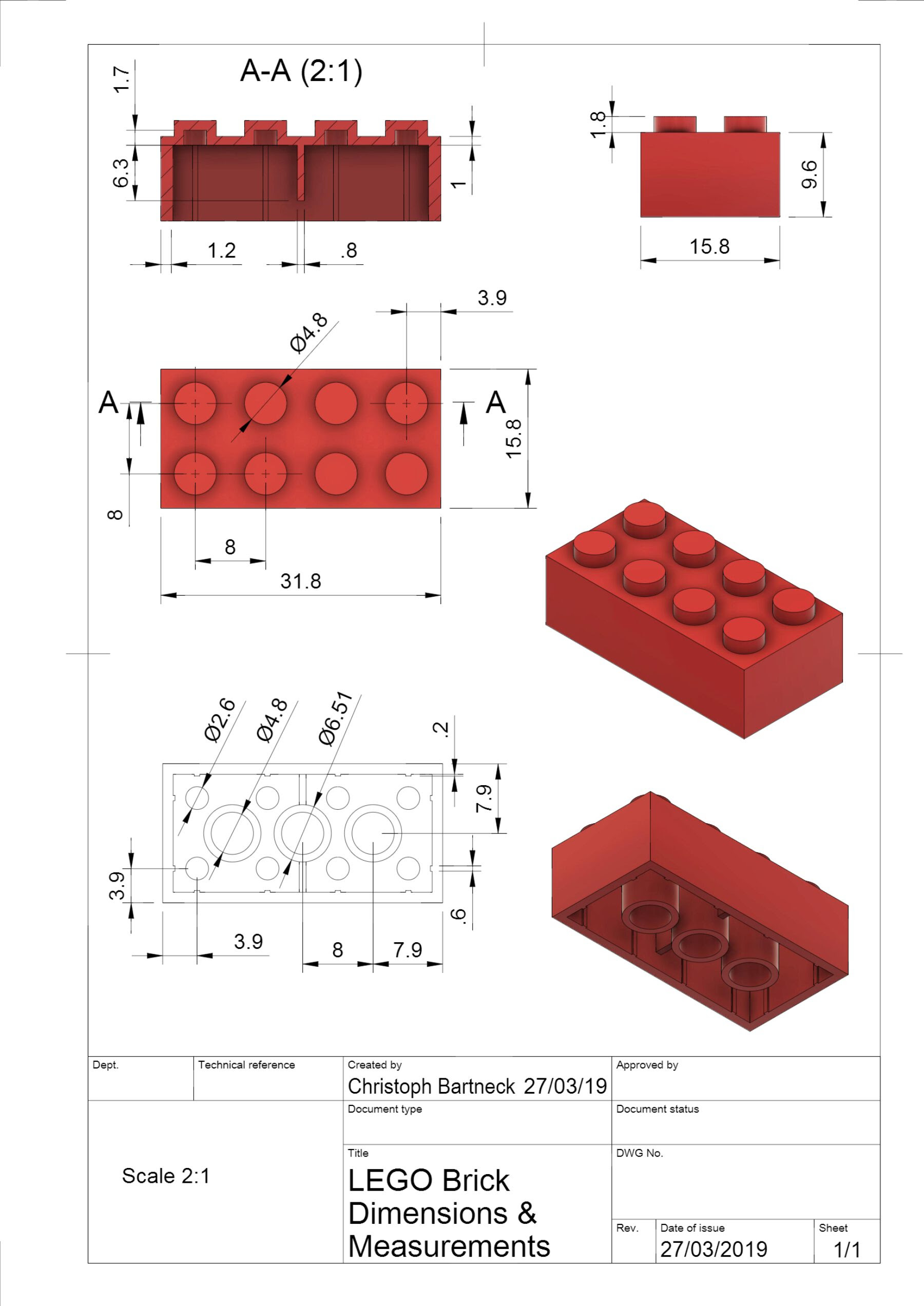
The biggest learning outcome intended for this week is to evaluate and select 2D and 3D software for our use throughout FabAcademy. Nowadays there is an infinite number of programs for both techniques that can get the job done. Some are better than other in very objective ways, but there is also a lot of subjectivity. Like I mentioned at the top of the page, it's just about seeing which program we feel most comfortable with. FabLab Barcelona's way of helping us find out which one we like best is through the simple exercise of using multiple softwares to build this Lego piece:
Rhino
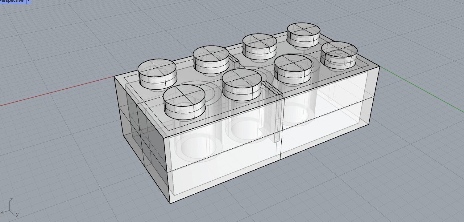
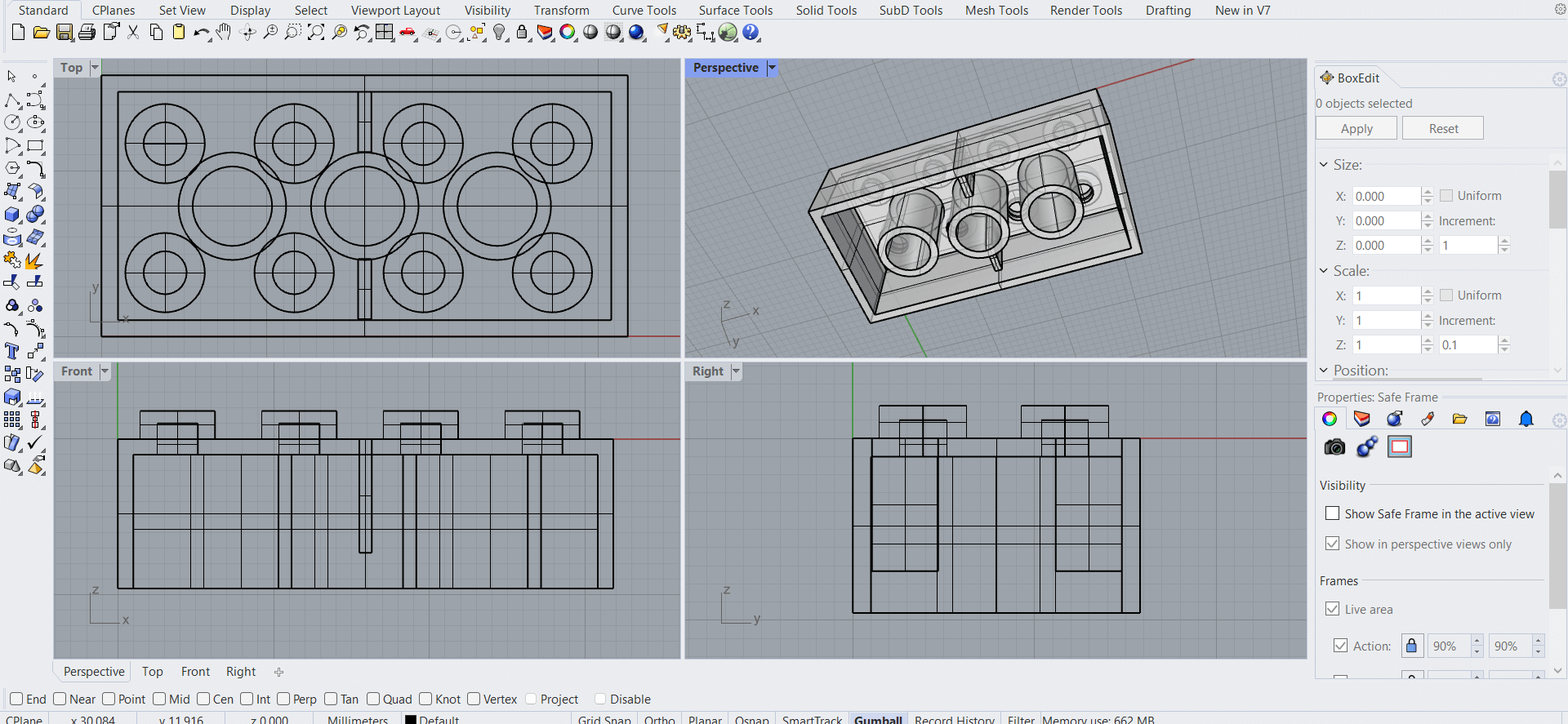
I took a course called "Naval Architecture and Design" in my second year of college. In this course I used Rhino 7 (with the Orca extension) to produce very basic plans and models of sailboats. So although I did have some previous experience with the program, it's been so long since I used it that it was like starting all over again. Luckily for me, Daniel walked us through the process of building the Lego brick step-by-step and I managed to keep up with him.
The design approach for building the Lego brick with Rhino consisted of drawing all curves in 2D from the top and then extruding them to build the brick and its parts. The basic outline of what we did is the following:
- Drew a rectangle for the main body
- Drew circles for the top parts (drew one and copied and moved the rest)
- Extruded the rectangle into a block
- Extruded the inner space of the block back in by offsetting and pushpulling
- Extruded the circles into cylinders
We ran out of time in class but already had the main structure done. I finished the rest of the structure at home the following day and, naturally, found using the program much harder to do by myself. Nevertheless I acquired a decent result. I wouldn't say this is my go-to software but I would still like to continue getting better with it since it is a very powerful tool.
My design file can be downloaded here.
OpenSCAD
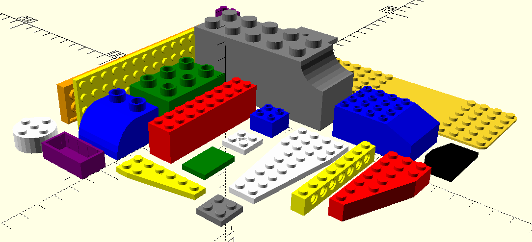
Considered an outdated and simple program, OpenSCAD proved to be very fun. Xavi provided us with the printed version of this cheat sheet. He then gave us a rundown of the platform, ran us through a basic example, and then showed us the LEGO.scad library.
For the basic example, we managed to produce the following model
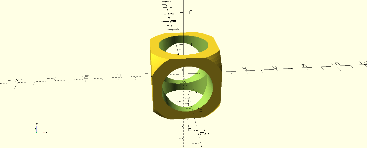
with a code as simple as
$fn=100;


difference(){

intersection(){

cube(4,center=true);


sphere(3);


}


cylinder(10,1.5,1.5,center=true);


rotate([90,0,0])

cylinder(10,1.5,1.5,center=true);

}
My design file can be downloaded here.
Then, for the Lego exercise, I first looked for the code to build a 4x2 brick within the library examples document. So I was able to produce this model
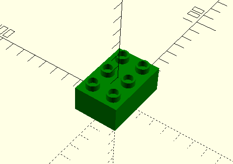
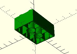
with this very simple code:
use
color("green")
place(0, 0, 0)
block(
width=2,
length=3,
brand="duplo",
reinforcement=true,
stud_type="hollow"
);
My design file can be downloaded here.
The OpenSCAD class was short, so we didn't have time for anything else. However, I wanted to try building the Lego block without the use of the library. Xavi put the code for doing this in our local class documentation, so I followed along by copying, pasting, and rendering the different steps. Basically:
- He created a cube, made it parametric, and changed the color
- He created the top cylinders
- He defined the internal walls
- He created the internal cylinders
So that the code ended up being:
// OpenScad special variables

$fn = 50;


//Lego brick parameters


brick_width = 15.8;

brick_length = 31.8;

brick_height = 9.6;


cyl_diameter = 4.8;

cyl_height = 1.8;

number_cyl = 4;


// Step 3

brick_wall = 1.2;


// Step 4

number_cyl = 4;

// Step 6

minicyl_diameter = 2.6;


// Step 10 - Int cyl

intcyl_diameter = 6.5;

intcyl_diameter2 = 4.8;

// End parameters


module lego_brick(){


// 3D Model

// Boolean Operator

union(){ // Lego Piece

color("red")

difference(){ // Cube walls


cube([brick_width, brick_length,brick_height],center=false);


translate([brick_wall,brick_wall,-brick_wall])

cube([brick_width-brick_wall*2, brick_length-brick_wall*2,brick_height-brick_wall],center=false);

}


// Top Cyl

for (a =[0:number_cyl-1]){


// Step 2

translate([3.9,(3.9+(8*a)),brick_height])

cylinder( h = cyl_height, d=cyl_diameter, center = true);


// Step 4

translate([3.9+8,(3.9+(8*a)),brick_height])

cylinder( h = cyl_height, d=cyl_diameter, center = true);

}


// Internal Cyl

color("yellow")

for (a =[0:number_cyl-2]){

translate([brick_width/2,8+8*a,-0.2])

difference(){


cylinder( h = brick_height, d=intcyl_diameter, center = false);

translate([0,0,-brick_wall])

cylinder( h = brick_height-brick_wall, d=intcyl_diameter2, center = false);


 }

}

}

}


lego_brick();
and the model looked like this:
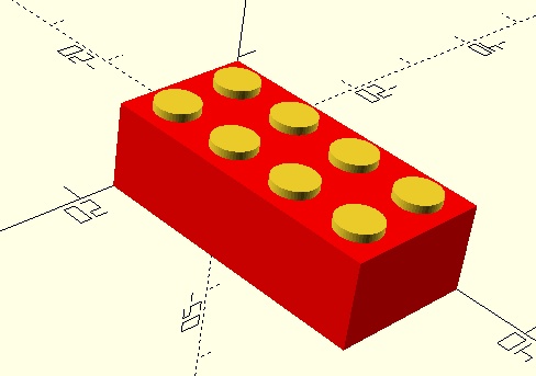
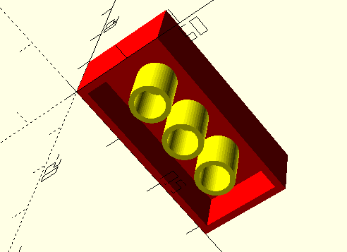
My design file can be downloaded here.
The way this program works is very different from the other ones I have used and the other ones we tried this week. It was very fun and cool to work with. However, it is not as powerful as the other programs and it doesn't do everything I need from a CAD package, so it unfortunately wont be my "go to".
Fusion
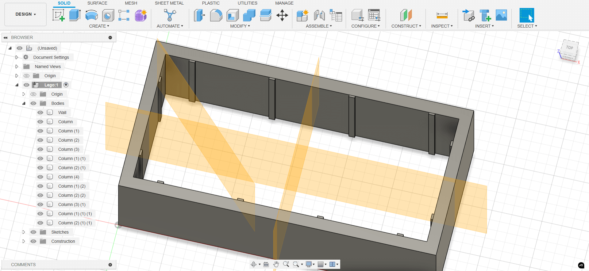
Fusion was by far the most intuitive program for me this week. Didac gave us a brief overview of the platform and then guided us through the modelling of the Lego brick. Just like with Rhino, our approach consisted of sketching in 2D from the top and then extruding to build the brick and its parts. The basic outline of what we did is the following:
- Sketched the main block, offset the inner wall and extruded it
- Sketched, extruded, mirrored, and patterned inner columns
- Sketched and extruded top surface for block
- Sketched, extruded, and chamfered the top cylinders
- Sketched, patterned, extruded, and boolean-differentially removed inner holes
- Sketched, offset, patterned, and extruded inner cylinders
I later realized I forgot to put the middle wall inside the block. In the end my Lego block looked like this:
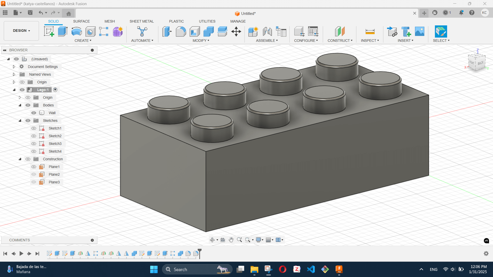
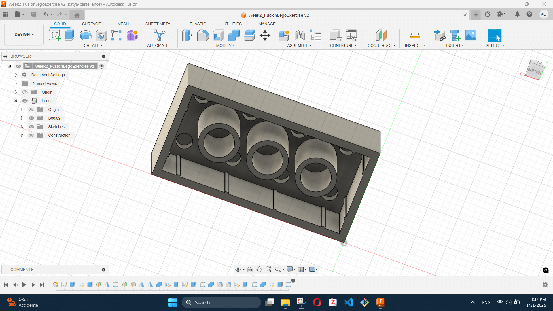
I really enjoyed the workflow of Fusion. It is a very powerful tool with which I feel pretty comfortable experimenting. By the looks of it, this one might be my "go to".
My design file can be downloaded here.
Blender
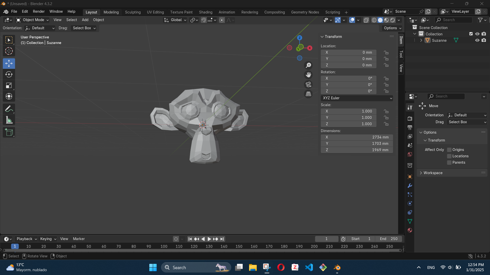
Adai showed us how to do some basic functions on blender (which is how I met Suzanne) and then he guided us step by step in the creation of our Lego block. He gave us a printed version of this cheat sheet. I will admit that I spent a solid hour trying to figure out why every time I changed an item's dimensions the scale would change. I did not google it from the start or asked Adai, which was a bad move. I ended up partly listening to the steps to create the block and partly getting my issue fixed. After a quick google search, I managed to discover I was sizing objects in the wrong mode and thats why the scale would move with the dimensions. After I managed to get the program set up well, the program was actually quite enjoyable. The basic outline of what we did was:
- Created a cube with the dimensions of the block
- Created a cube with the dimensions of the empty space inside the block
- Created a boolean difference modifier to subtract the volume of one block from the other one
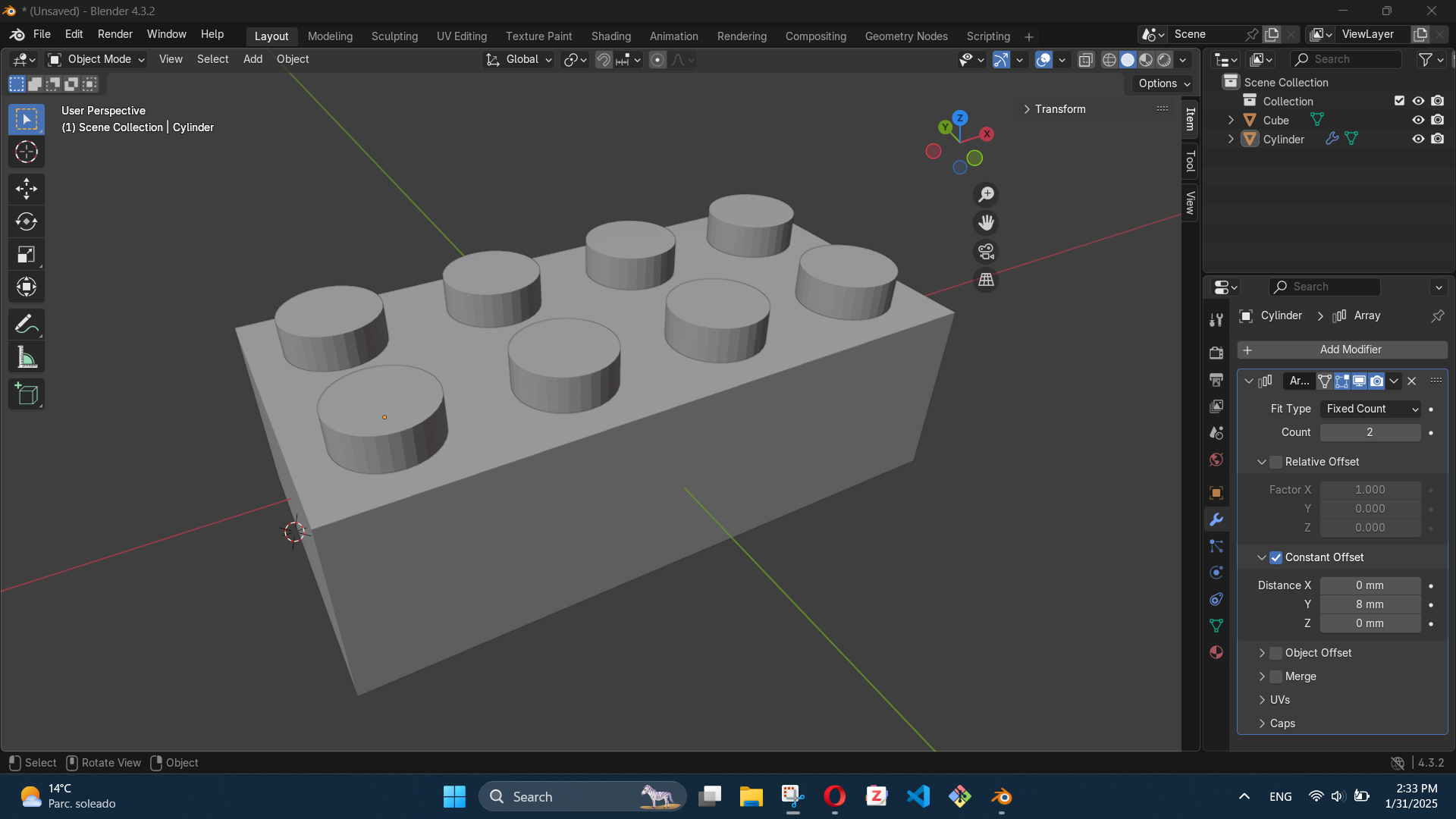
- Created the cylinders for the top of the block and created an array to multiply them
- Created cylinders with the dimensions of the inside holes and created a boolean difference modifier to subtract their volume from the outer cylinders
- Created the inner cylinders
- Created cylinders the size of the empty space inside the inner cylinders and created a boolean difference modifier to subtract their volume from the main ones
- Created the middle inner walls by creating cubes
After a long fought battle, my Lego block ended up looking like this:
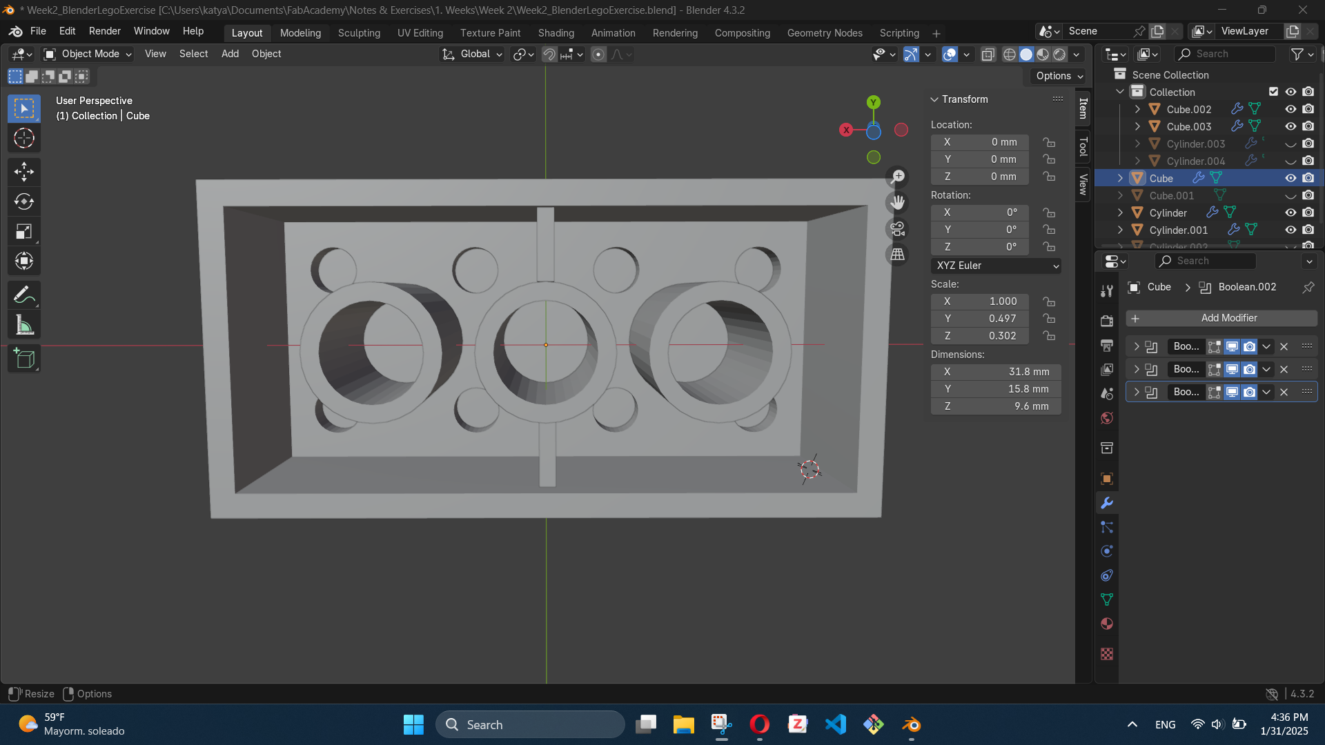
My design file can be downloaded here.
Other Softwares and General Notes
While we didn't use them as part of the Lego exercise, we also learned some other programs. Santi taught us how to use Inkscape and TinkerCAD and showed us WOMP. Inkscape is essentially the open source version of Adobe Illustrator. It is great to work with 2D modelling using vectors. TinkerCAD is an online program that can be used for 3D modelling, electric circuits, and codeblock design. Both softwares are very interesting and useful in their own way. I'm sure I will be using both of them for one thing or another in the future.
Some things I noted and would like to improve for my own future modelling experience are:
- Labeling components/bodies/solids in an effective way. Our classes were short and fast-paced so we didn't focus as much on this, but it is a habit I want to make sure I develop.
- Documenting more and doing it as I go. Maybe taking a picture of each new feature might be too time and storage consuming, but remembering to take more pictures of the process is another habit I want to make sure I develop.
Assignments
1. Model (raster, vector, 2D, 3D, render, animate, simulate, ...) a possible final project
I wanted to use this assignment to model my final project with as many techniques and softwares as possible. However, I obviously had time limitations, so I stuck to one 2D software and one 3D software. As time keeps passing I do intend to try out different softwares, even if it is just importing files from other softwares and then playing around with them.
2D Vector Modelling with Inkscape
I started to plan this project with a basic external sketch last week, so I wanted to start this week with a basic sketch that combined the externals, the internals, and the CAD software we learned to use this week. I decided to use Inkscape for this since it is a great tool for 2D modelling with vectors. My final sketch ended up looking like this:
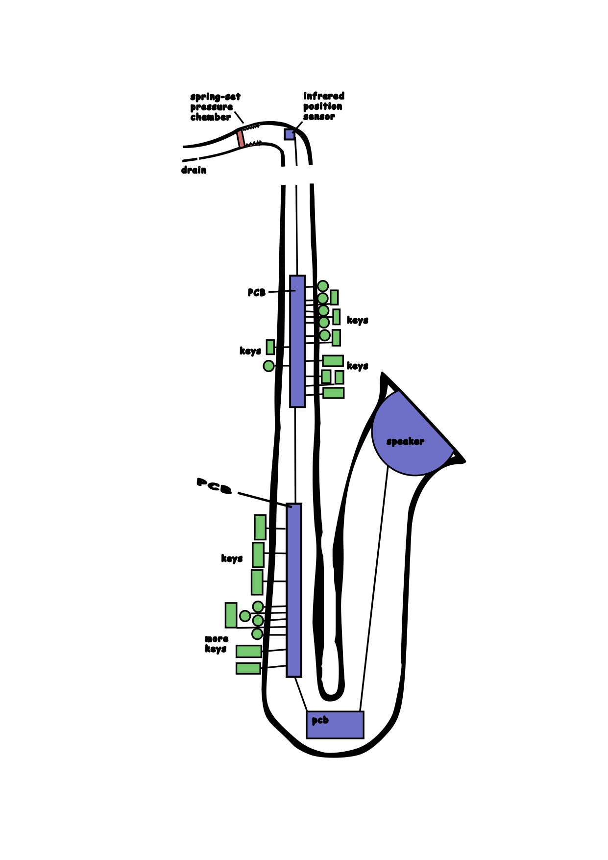
and I accomplished it by following these steps:
- I downloaded a vector image of a tenor saxophone's silhouette
- Opened Inkscape and imported the image
- Traced the bitmap of the image into a new layer and hid the layer with the original image
- Used the Node Tool to modify the silhouette into the outline I wanted for my pieces
- Used the rectangle and ellipse/arc tools to create shapes that represented the components
- Used the pen tool to draw all the lines that joined shapes and also the springs on the pressure chamber
- Used the text tool to label all the components
Satisfied with my concept sketch, I exported the file as a pdf and used ilovepdf.com to convert it to JPG format. I also downloaded it as a SVG document. The SVG file can be downloaded here.
3D Modelling with Blender
Blender and Fusion were the two most intuitive softwares for me, so I wanted to do this assignment with one of them. I originally started with Fusion but I kept getting too worked up about specific details, so I decided to do a design focusing on the visuals and the actual viability of my ideas for the structure, and then work on the specifics. For this reason, I moved over to Blender. In the end, my model looked like this:
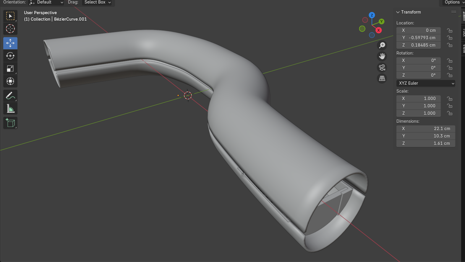
Currently, my idea is to print the neck of the saxophone as a single piece to prevent leaks from the pressure chamber. This piece will then fit into the main body of the saxophone, which I want to split halfway through the Z plane, in a way that the components can be easily installed, and have both halves connect with grooves. However, for my initial design, I split the neck through the X plane, so that I could easily see the internals and verify the viability of what I wanted to do with the components.
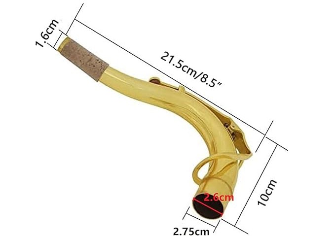
For this week's assignment my biggest struggle, other than getting a grasp of the programs, was the fact that I don't have a saxophone with me (yet! I am saving up), and I therefore don't have precise measurements at my disposal. Nevertheless, I managed to find a range of measurements online that gave me an average for the main parameters. One of the most useful sources I found was this project by the user "hungn" on Autodesk's community. I downloaded the file, played around with it in Fusion, and got some rough measurements for the neck piece. I also used this image from a saxophone neck for sale on amazon:
I tried sticking to real dimensions as much as possible when it came to the design. What I set out to achieve was to have an overall structure for the saxophone's neck, and have a detailed first version of the mechanism for the breath chamber. My idea for the breath chamber is to have breath push a sort of lid through the chamber, which will be pushed back by a very soft spring in order to reset it when it is not being played. At the end of the chamber, I want to have an infrared sensor that will detect how far or close the lid is, and use this as the base signal for the volume the instrument is being played at. I want the chamber to be as sealed as possible so that the measurements are precise, however I do need to add a small hole in the bottom. This hole will serve both the function of a siphon for any saliva, and as an escape for the air being blown in. The final version of this initial chamber model ended up looking like this:
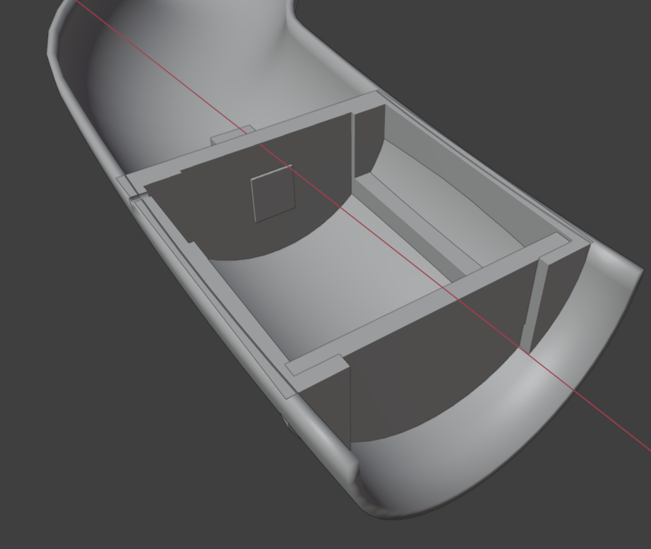
My design process was very trial and error, filled with google searches and re-do's. The steps I ended up taking for the general design of the neck pipe were:
- Googled "how to make a pipe follow a path in blender" and followed this tutorial:
- Created a curve circle with the diameter I wanted the pipe to have
- Created a Bezier curve with the shape I wanted the neck to have based on a hand sketch I did where I graphed the points of the curve
- I wanted to give the pipe a specific thickness. So I Googled "how to add thickness to mesh from curve blender" and followed a reply to this Reddit post that suggested applying a solidify modifier
- I wanted to split the pipe in half to make it easier for me to work on the inside components and to make them more visibly available. So I Googled "split a mesh object blender" and followed this tutorial:
- Going into edit mode and selecting all the vortexes of one half
- Pressing "P" and choosing "Selection"
- This created a new object with the selected mesh, so I just moved it out of the way to work on one half
Once I had that done, I focused on the pressure chamber. So for this, I:
- Created a mesh cylinder
- Fit the cylinder to the inside of the pipe in the section were I want the pressure chamber to be
- Created a cube that encapsulated the side of the cylinder that stuck out of the neck's half
- Created a boolean modifier on the cylinder, creating a difference between it and the cube, and then hid the cube
- Created a cube for the channel where the lid will slide through when breath is being blown in
- Created a boolean modifier on the cylinder, creating a difference between it and the cube, and then hid the cube
- Created a cube for the groove where the spring will be placed in
- Created a boolean modifier on the cylinder, creating a difference between it and the cube, and then hid the cube
- Repeated the last step on the other side of the channel
- Created a cube for the lid that will slide through the chamber
- The lid's cube extruded from the whole structure, and although I conducted plenty of google searches for different ways of removing the extrusion, in the end I created a torus that encapsulated the protruding parts of the lid's cube around the neck piece
- Created a boolean modifier on the cube, creating a difference between it and the torus, and then hid the torus
- Created a cube for the infrared sensor
Since this is a very preliminary model of my final project, some things I want to do differently in the next version are:
- Adding the springs in to the design
- Using more control points on the Bezier curve so that I can make the pipe smoother
- Modifying the taper of the shape to simulate real saxophone necks
- Making the measurements more precise
- Name my objects in a way that makes sense
My design file can be downloaded here. The next iterations of the saxophone's neck can be found here.
2. Compress your images and videos, and post a description with your design files on your class page
My general documentation process so far has been taking screenshots as I go and then naming them so that I know what week they belong to and what exactly they show. So far, I have rarely ever had to compress the images, since they stay around 300KB. However, for those heavy screenshots and any images I download from the internet, I have been using TinyJPG.com or ReduceImages.com. So I upload the images, let the site compress them for me, download the smaller image, and push that into my repository.
I then also learned to use ffmpeg to compress media locally. To install it, I followed these steps:
- Retrieved the source code through Git Bash by using the command:
git clone https://git.ffmpeg.org/ffmpeg.git ffmpeg - Downloaded the latest git master branch build from the git master builds section.
- Downloaded 7zip.
- Extracted the contents of the downloaded git master branch build file by right clicking the file and then selecting 7zip > Extract Here.
- Renamed the folder "ffmpeg" and moved it to the root of the C drive.
- Set the windows environment variables to add ffmpeg to the path by typing "Edit the system environment variables" into my computer's search bar, then selecting "environment variables" > "advanced" tab > "path" under the "user variables" section > "edit" button > "new" button. I added
C:\ffmpeg\binto the empty field and confirmed the changes with OK. - I confirmed the installation by running
ffmpegon the command prompt in my computer.
Having ffmpeg installed, means I can now compress media from my GitBash terminal. For example, the video below, which shows me compressing a video, was then also compressed with the process seen in the video (very Matrix). I followed the instructions from this GitHub Gist.
When it comes to design files, my files for this week were very small, so I didn't have to compress any of the 3D models. For the 2D model of my assignment, I exported the file as a pdf and used ilovepdf.com to convert it to JPG format, like I mentioned before. Luckily the JPG was quite small so I did not have to compress it.