Flight Electronics
I have been working on an AT MEGA 328 PU based controll board.
We designed the board in Kicad with my instructor's guidance.
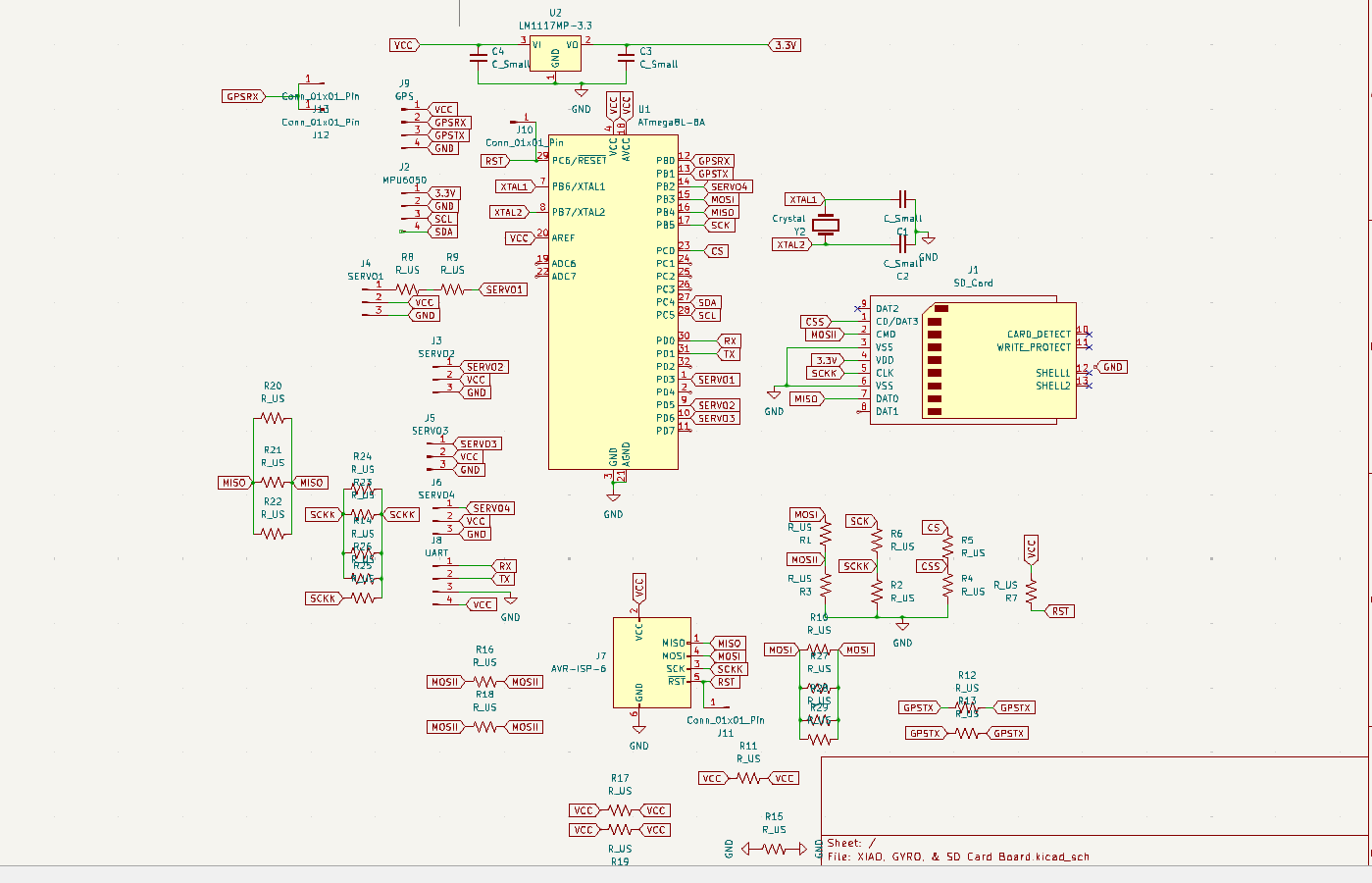
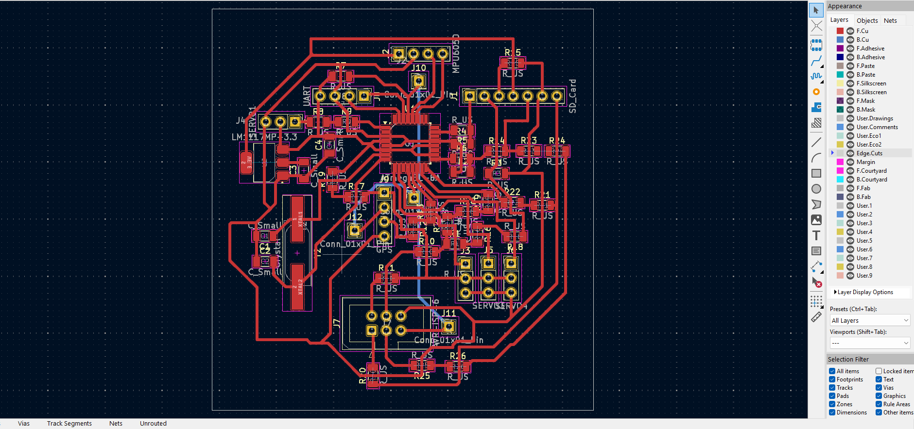
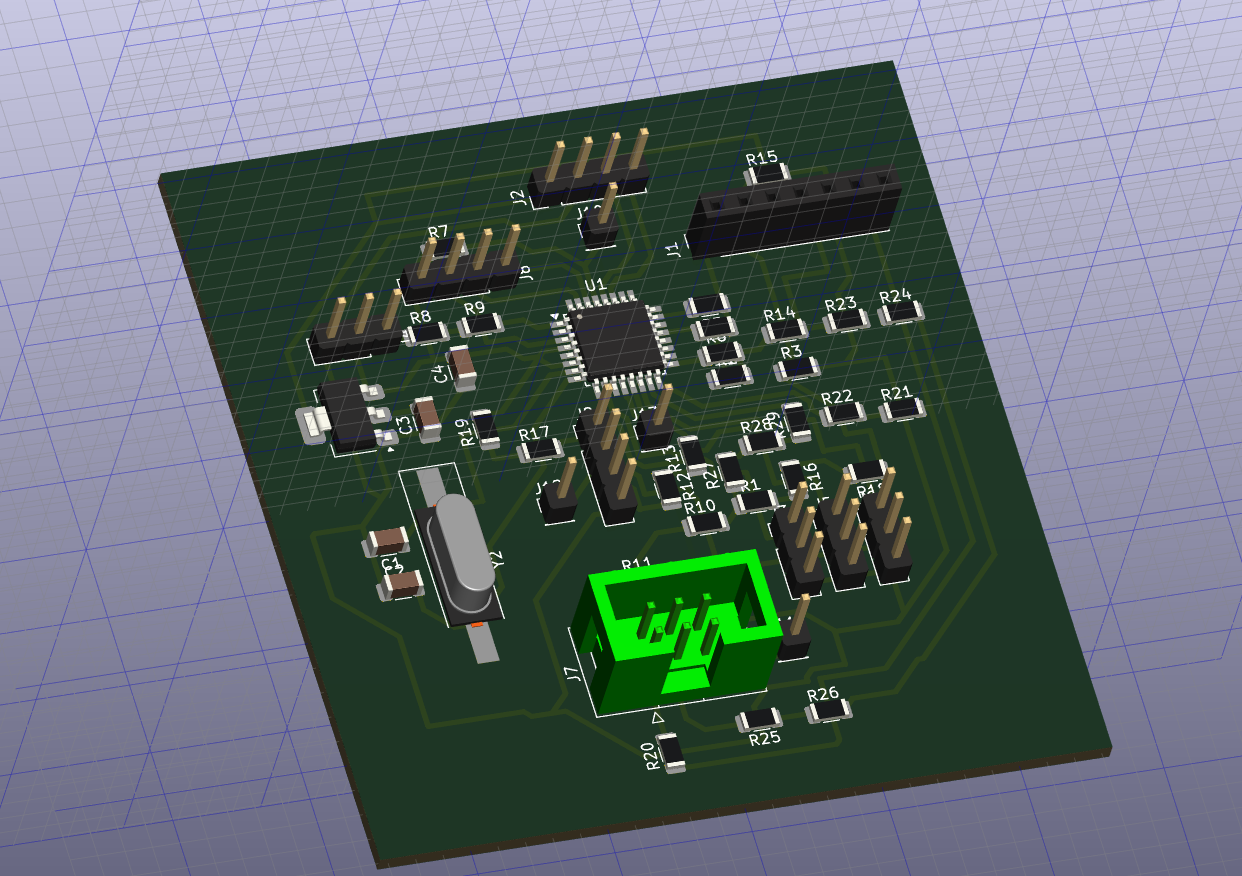
The board has the AT MEGA chip, a GPS module, 4 pins to connect a WiFi Module, 4 servo motor 3-pin connectors, and a programmer (in Green) as the main parts amongst others.
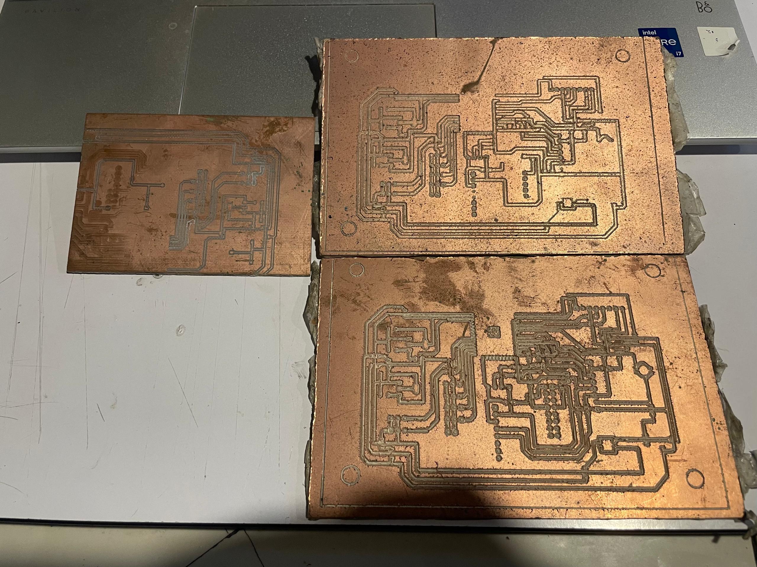
It was a nightmare though to print it on our machine (SRM 20). The Microchip's footprints were hard to make with precision.
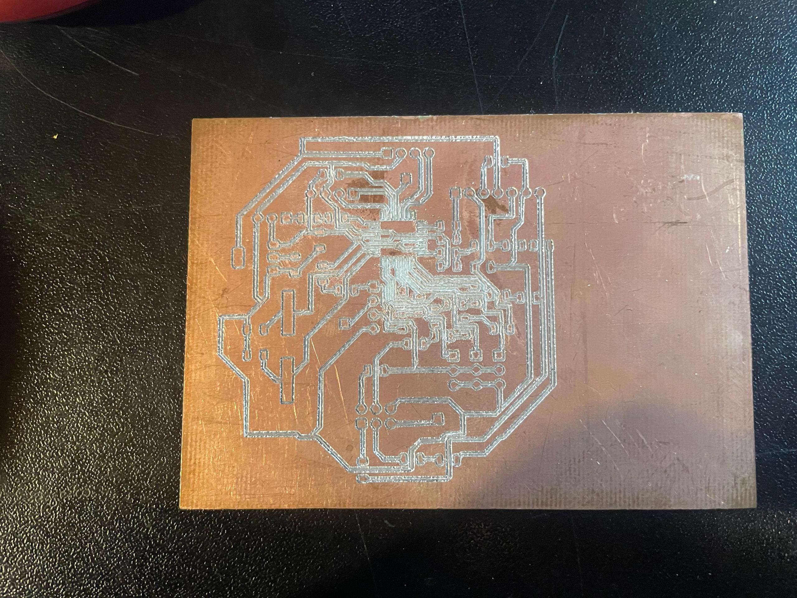
first attempt: printed inverse by mistake.
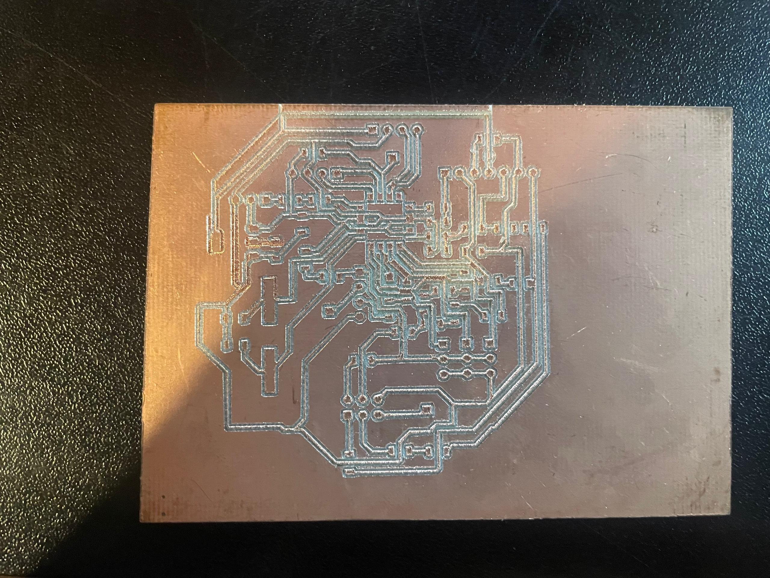
2nd attempt: the chip footprints formed pairs instead of coming out individually.
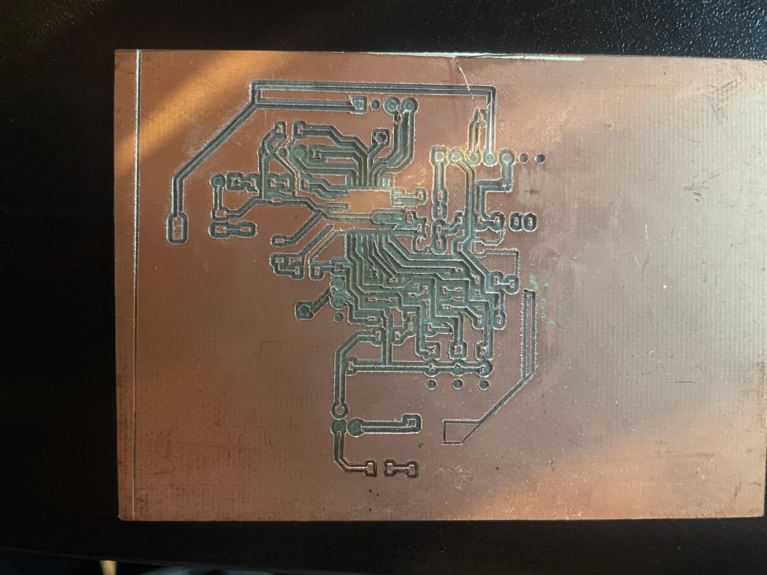
This failed mid-way due to unleveled of the bed.
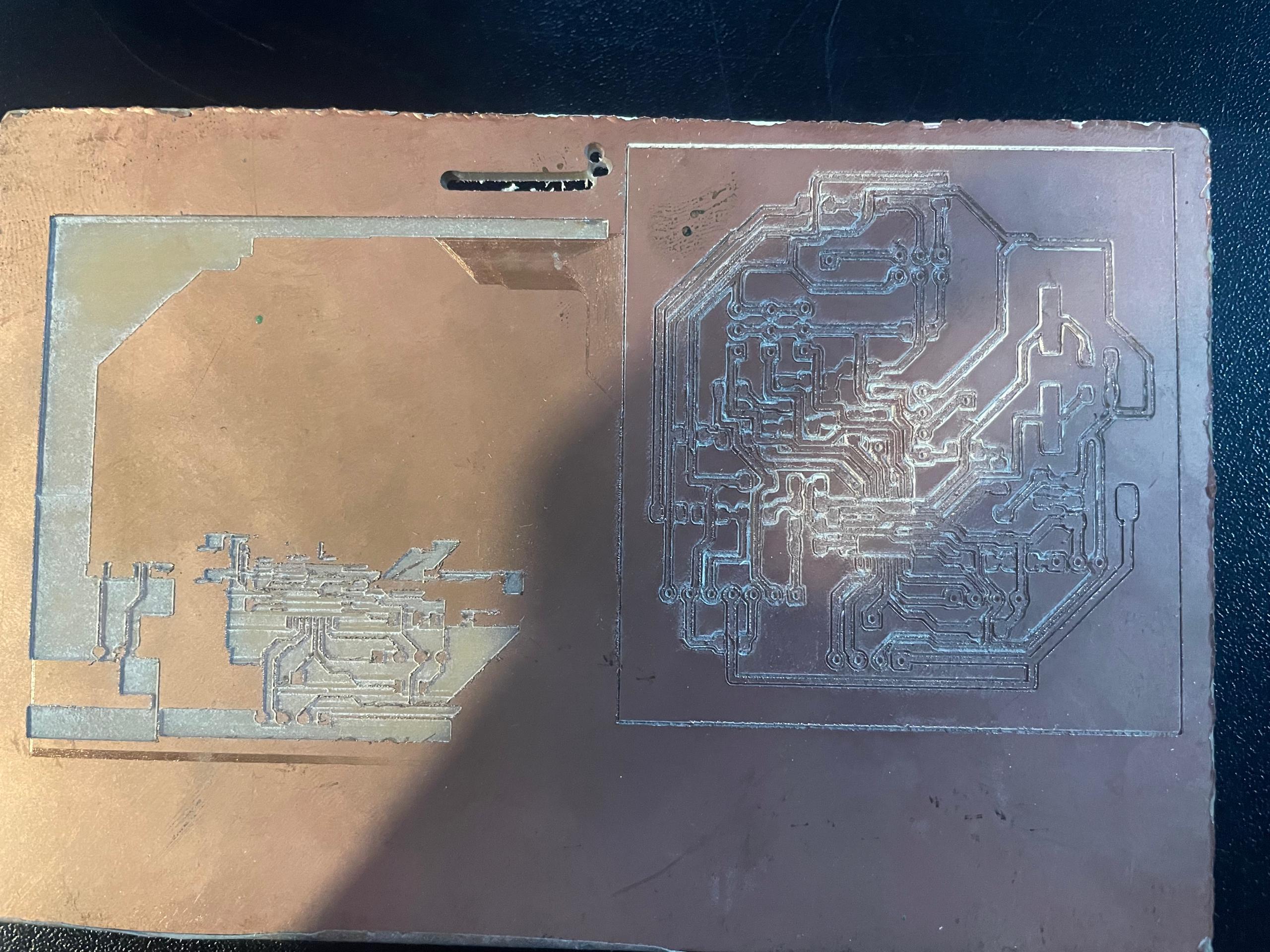
This picture has another faild attempt and on the right side a successful attempt. But immediately after that we realized how much of a nightmare the soldering will be.
we also didn't have the chip, and other sensors to solder and start programming. So I figured an ESP32 C3 based board would be easier to solder (more spaced footprints), it has a built-in Wifi module, and I already have some projects/codes to integrate for the final project.
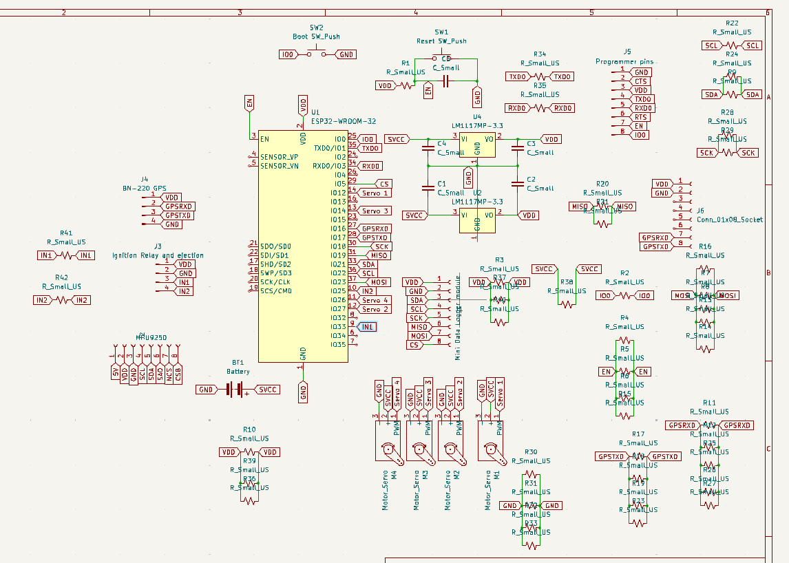
In the end we made a new similar board, but based on the ESP32-DEVKIT-V1 chip and it very well documewnted in electronics design. Link to Electronics Week
ESP32-WROOM/ESP32-DEVKIT-V1 Chip
We went for this chip for a couple of reasons:
It has built-in wifi, a more spaced footprints, and we didn't have either this chip or the ATMEGA, we were about to purchase more electronics at our Fablab.
So I went in Kicad and design a new PCB from the ground up. I enjoyed regardless of all the work and time it was costing me in the grand scheme of the Fab Academy (I wanted to master it).
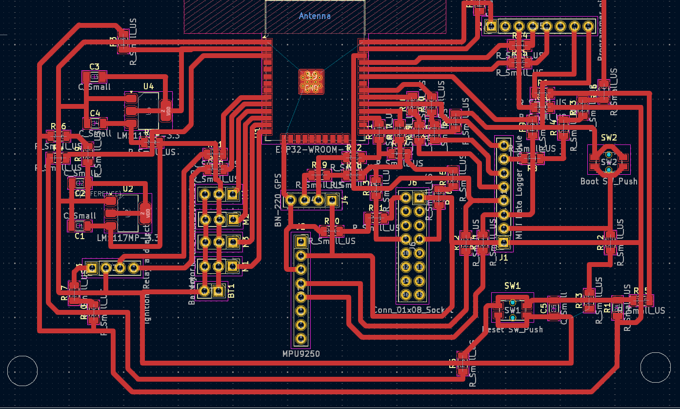
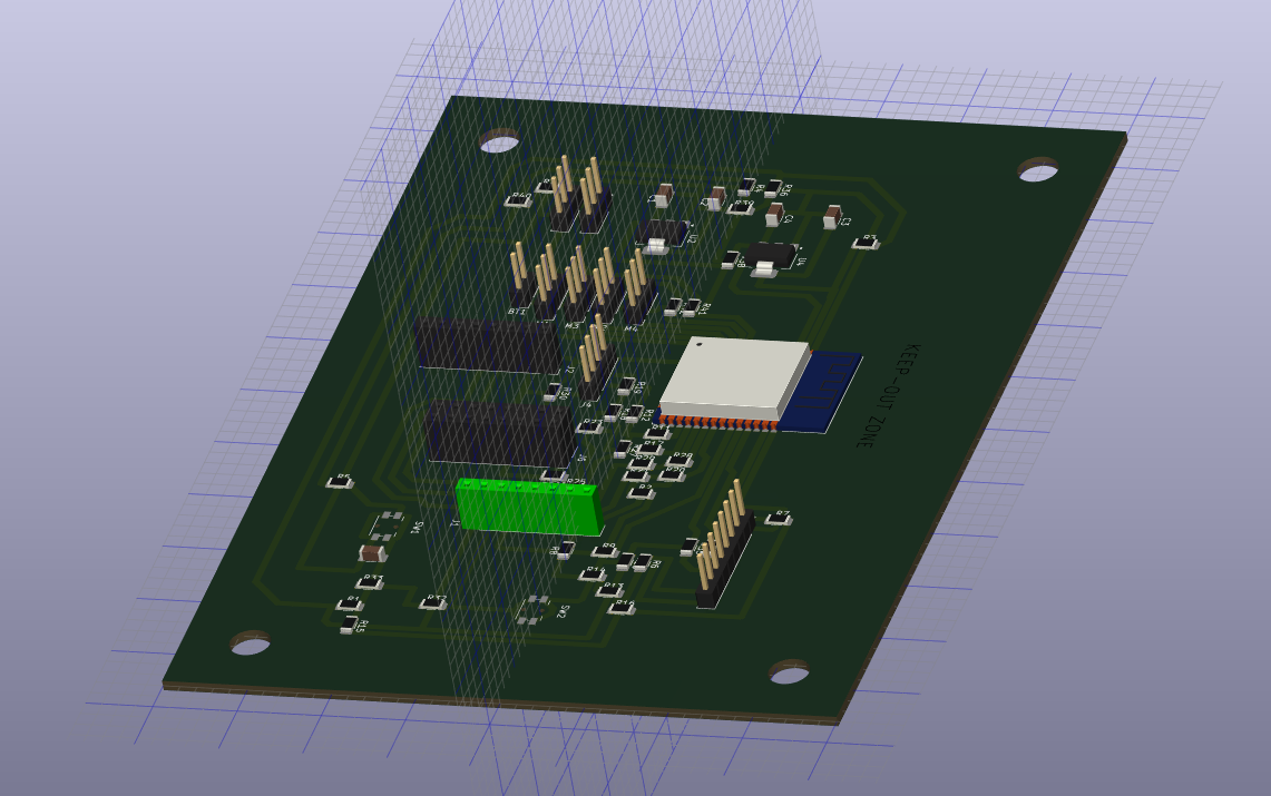
I designed a box for it as well but lost it amidst an accident (1.5Kg Rocket fuel caught fire in our lab and we lost a few stuff in the craziness).
.png)
A few prints of this version below:
The model was basically good to go, but it was too big to fit inside our rocket (version1 and version2[which was even a smaller rocket]), so design was havily modified with my instructor Lambert, and this time we rebuilt it again from EasyEDA.
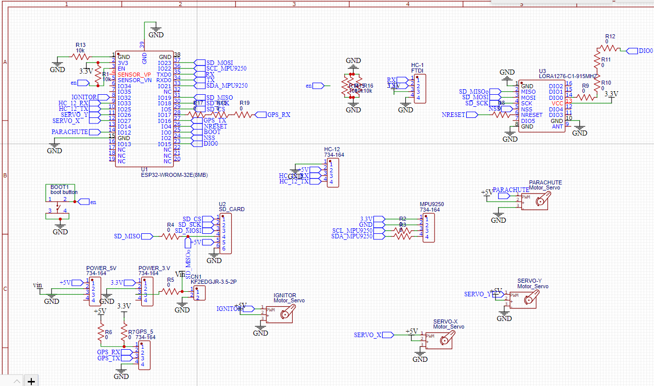
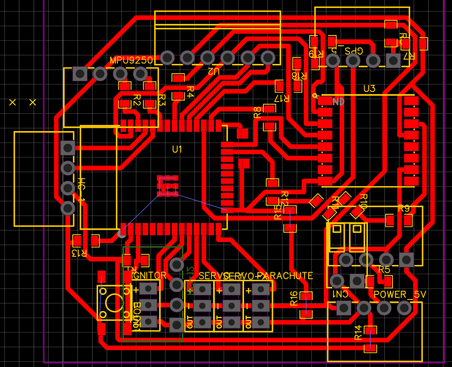
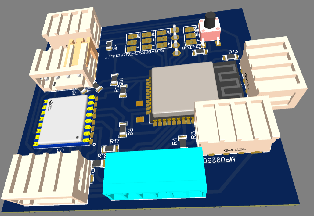
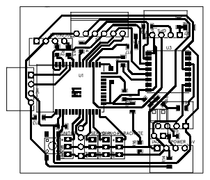
PNG of the PCB
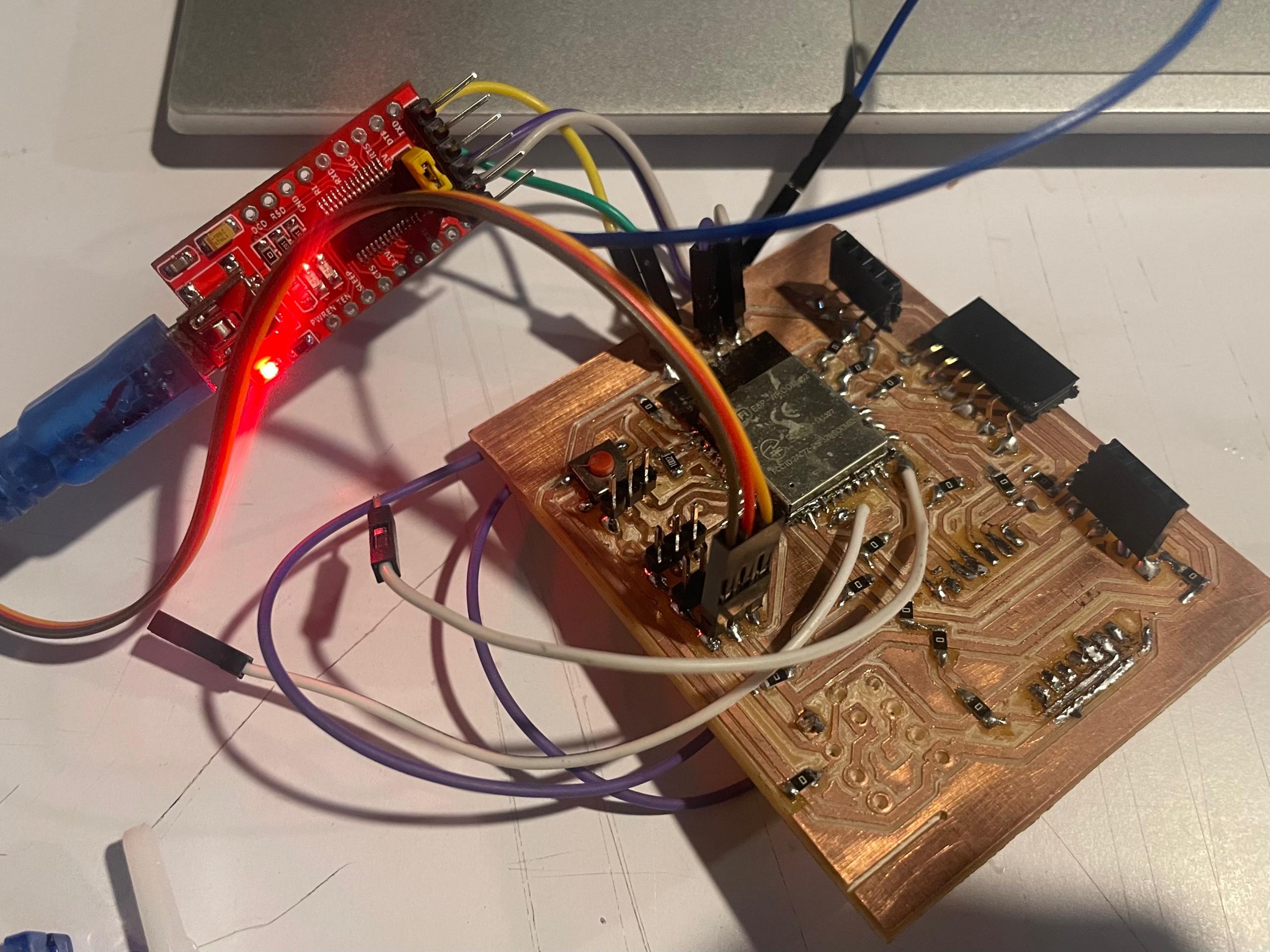
A simple test of servo controls with the board. This is because in the future (after Fab Academy, I want to further develop the project and include thrust vectoring by gimbaling the rocket motor).
We are also going to use the servo to open the parachute bay, which is the rocket nose, Once the computer senses a decrease in apogee (or altitude). The servo will be triggered by the gyroscope data.
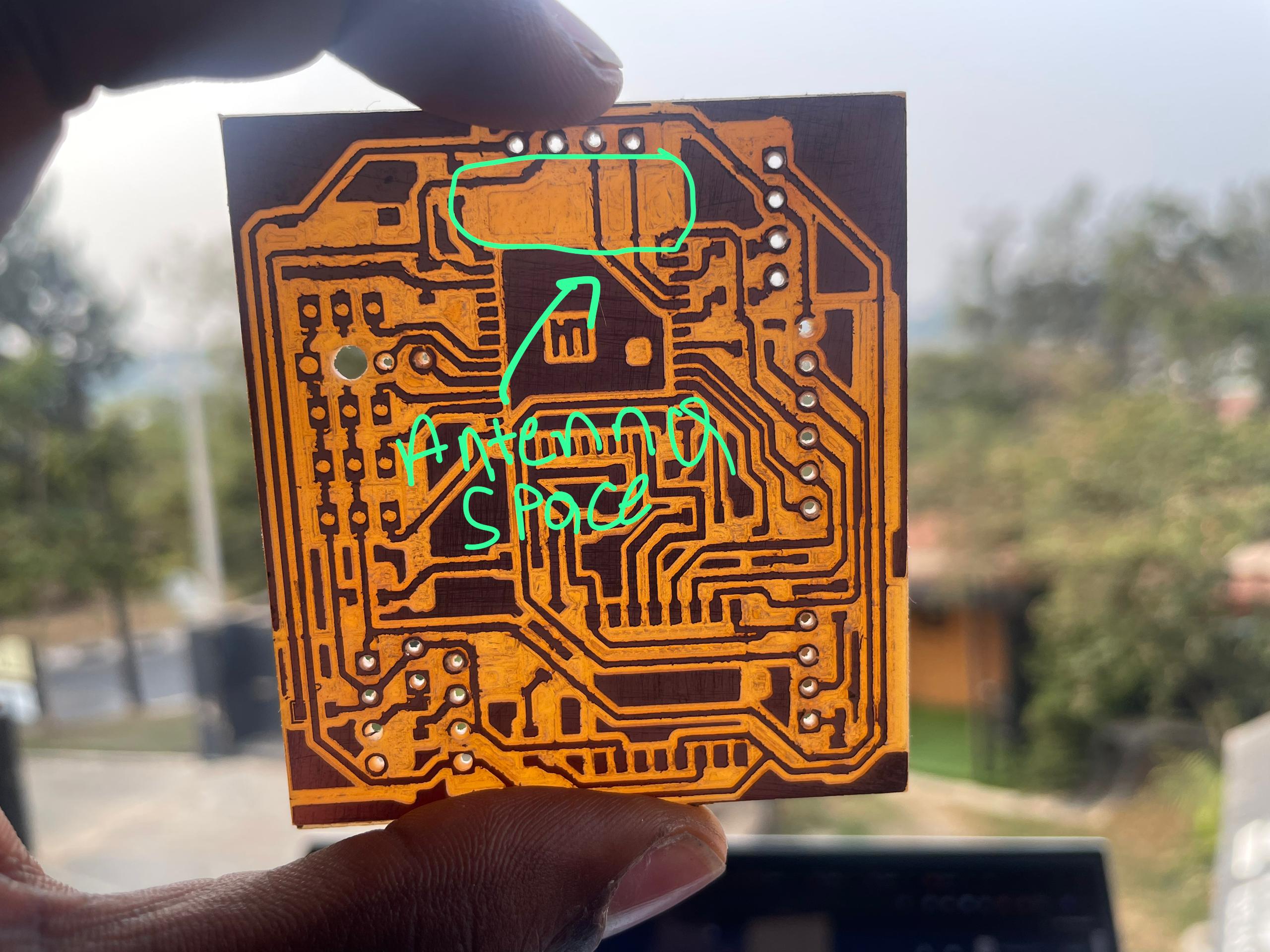
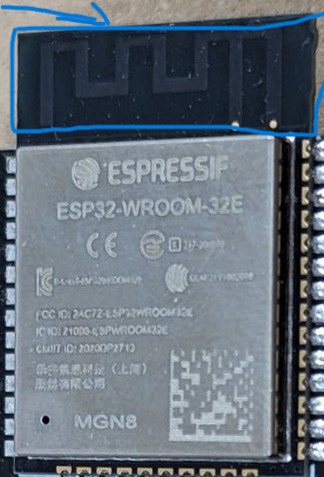
If you are going to be using your board with wireless programs, you want to remove the copper beneath the antenna to eliminate electromagnetics inconsistencies that can lead to noise or misbehaviour of the ESP built in antenna.
This the Software for the computer
(the Documentation is done as comments within the codes for times efficiency's sake.)
Flight Data recorded
Flight 1
Flight 2
One deduction we made From this data is thatwe were able to record the speed of the rocket's initial jump, which was about 3.7km/h.
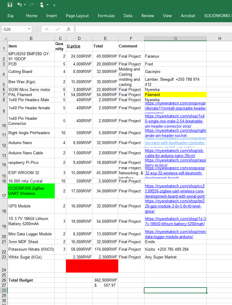
BOM
Project Development
- NKP/KNO3: Potassium Nitrate & Sugar
- PVC Pipe
- Processor: ESP32-DEVKIT-V1
- Data logger
- Gyro & Accelerometer
- RF transmission
- Data recorder: SD Card
- Parachute Deployment
- Body Tube
- Nose Cone: Electronics Housing
- Center rings
- Shock Cord
Contact
Happy to receive your inquiries.
Location:
Kigali, Rwanda
Email:
philemonmail77@gmail.com.com
Call:
+250 780 716 155
