
Week 4: PCB (Printed Circuit Board) fabrication
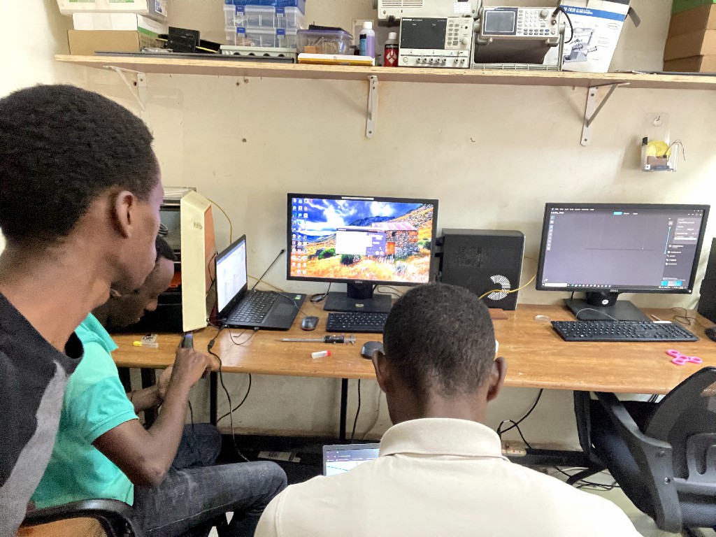
Group work
It was personally very confusing how we should produce boards we haven't designed, and more so because I never designed one before.
Then I realized that we just need to work with my coleagues to print the quentorres. Our Instructor gave us a very hands on deep dive on boards (types, layers, pads, via) and production processes.
And it was all fun afterwards. We printed a couple of boardsd and did the soldering together. I had a couple of failed ones with the SRM-20, especially when drilling, So I didn't make it to customization.


Then I downloaded the quentorres PNG files from Adrian Torres. to start producing a the board myself.
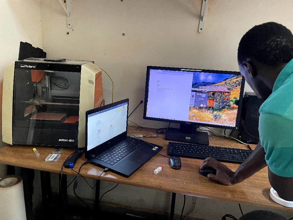
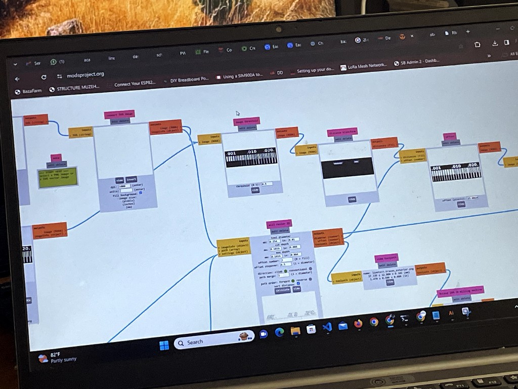
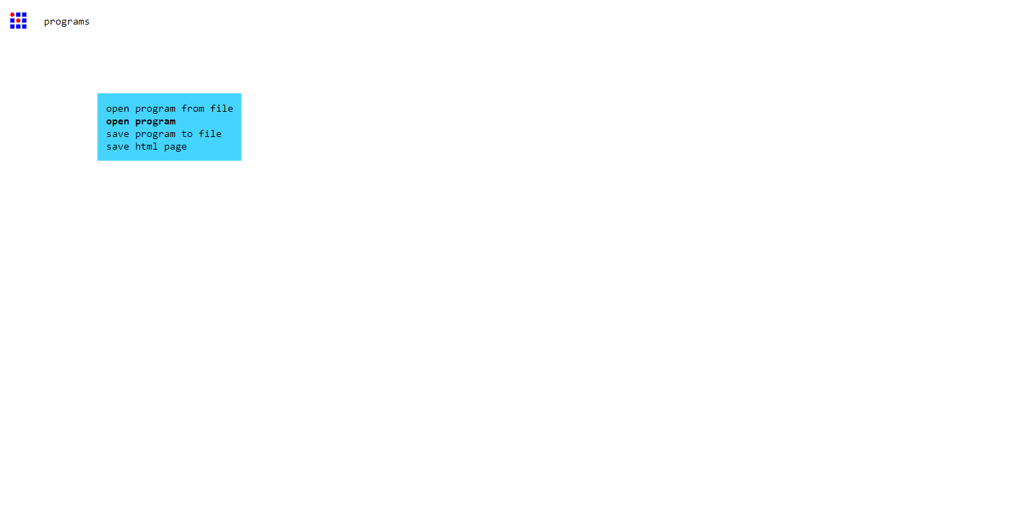
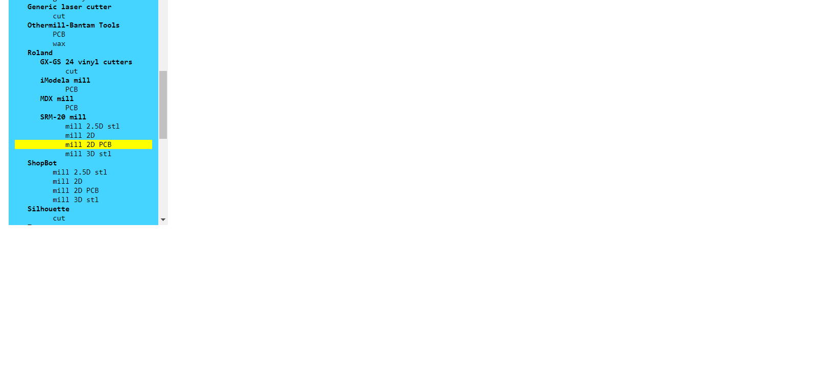
I generated the toolpath for our machine (SRM-20) to print and cut the Quentore microcontroller development design with Fab Mods.
the board files: Traces, Drills, and cutouts as Picture-listed here respectfully:
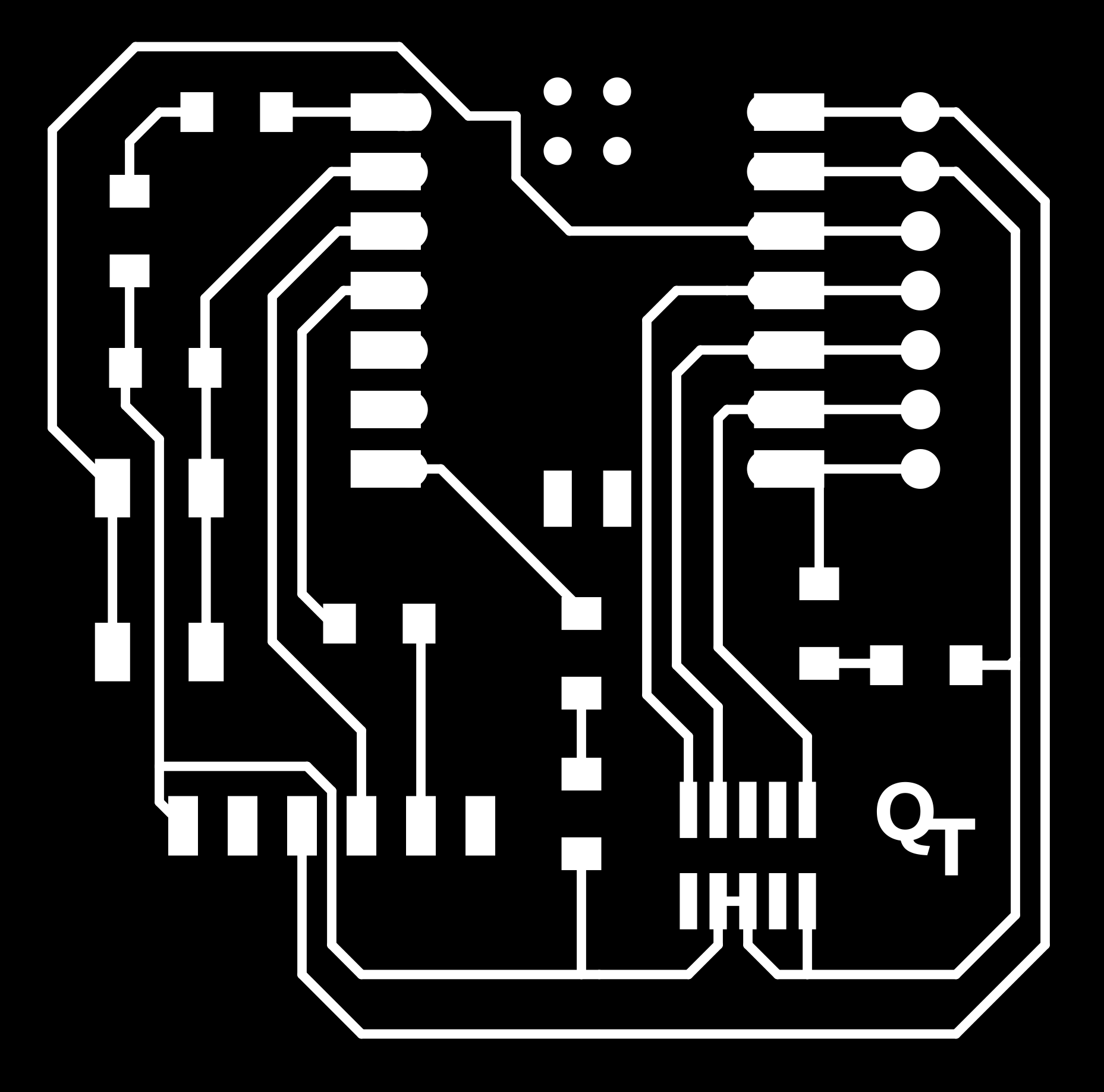

-
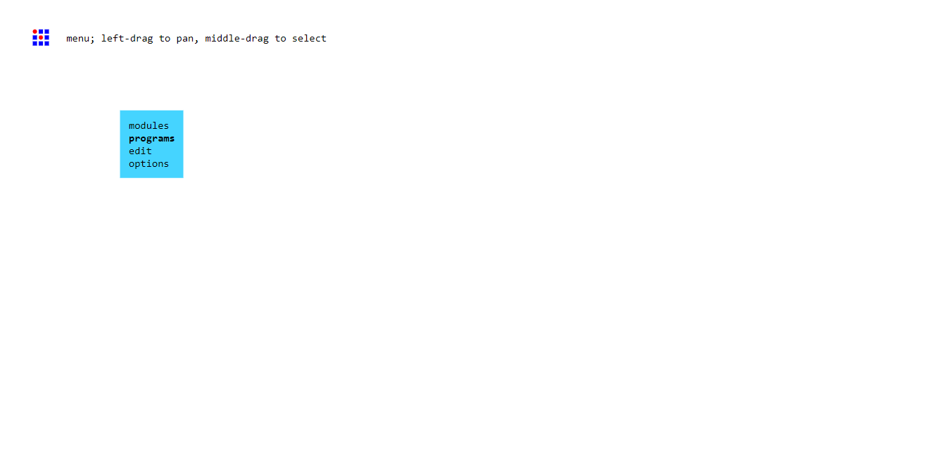
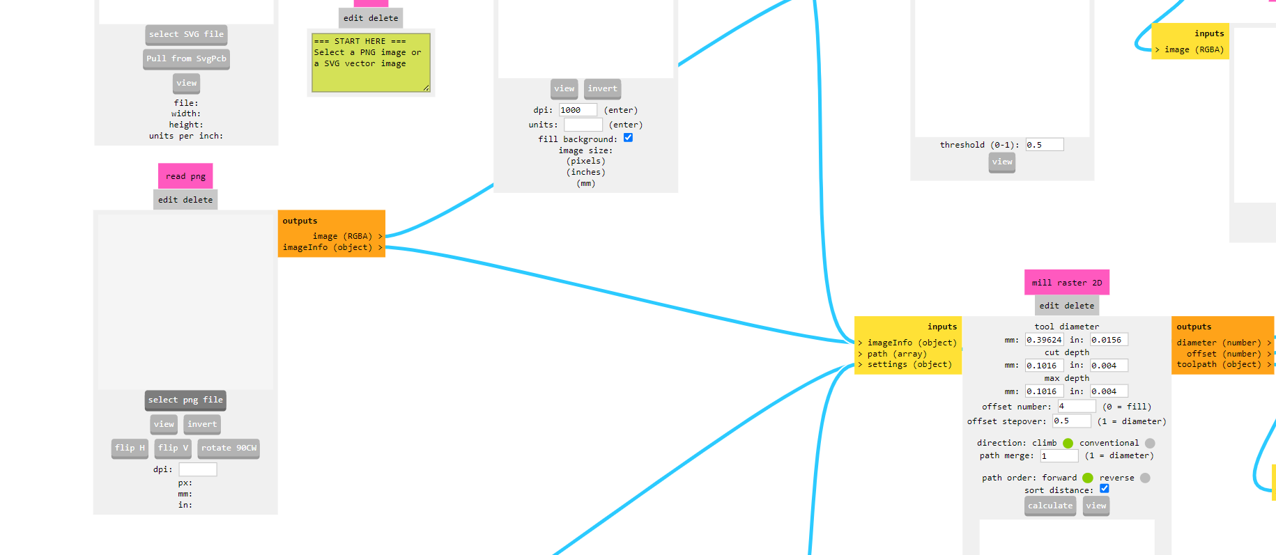
Set up the tool size and cut depth Itried lots of offsets before I understood what do: It's how much cleared of unnecessary copper layer your final PCB is. This one had the default 4 [passes around the trace].
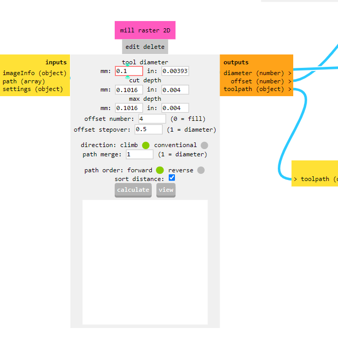
Hit calculate
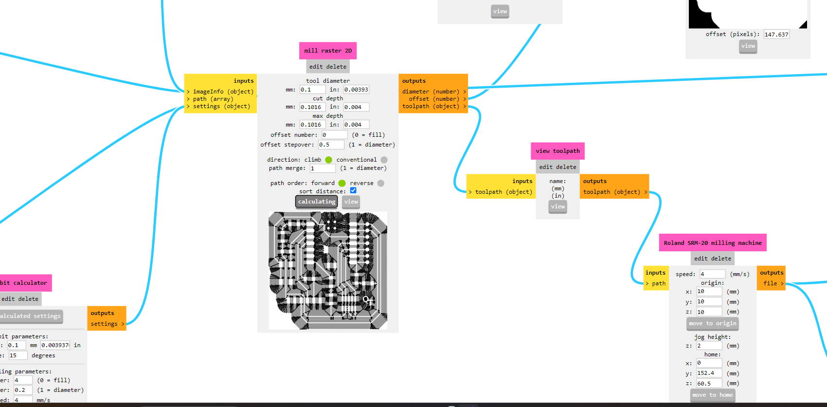
If the lower in put to output toggle is turned on, the toolpath file will be immediately downloaded. See pitcure below
.png)
-
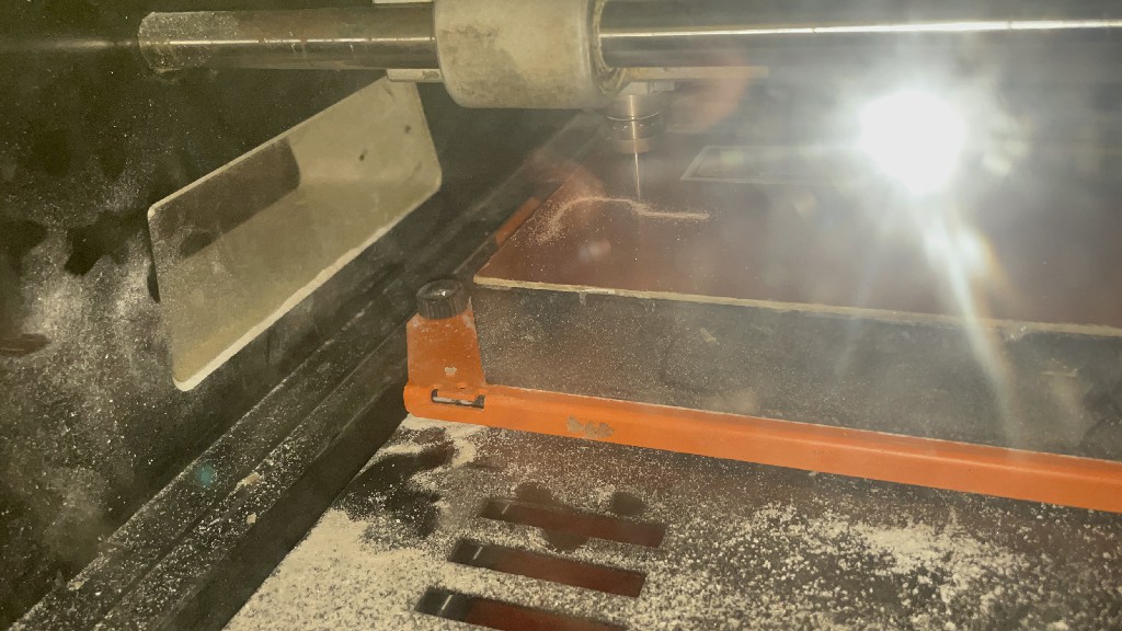
I insterted the drill bit in the machine.

Then I took starting coordinates [in VPanel for SRM-20] from where the machine will start to print circuit.
.png)
.png)
.png)
When you hit cut in VPanel Dashboard, it takes you to where you tell it which toolpath to execute. You want to delete the files you find in there, if you're sharing a computer, so that you're not confused.
Hit "add" button, then you will let you browse your computer to find the desired toolpath file wherever you saved it.
.png)
When you hit the "output" the machine will start the spindle and move according to the toolpath, reverse engraving your circuit on the Copper layered piece.
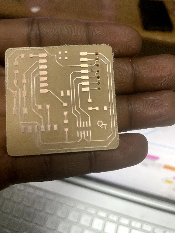
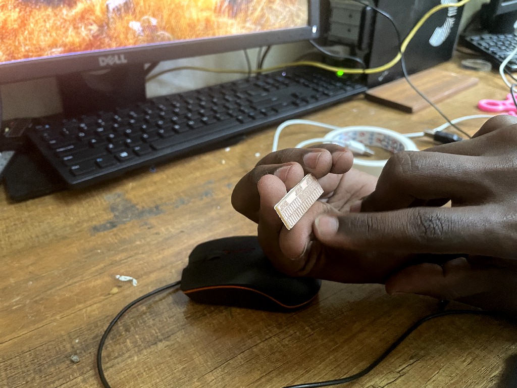
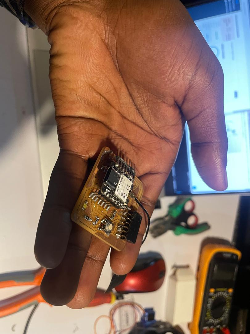
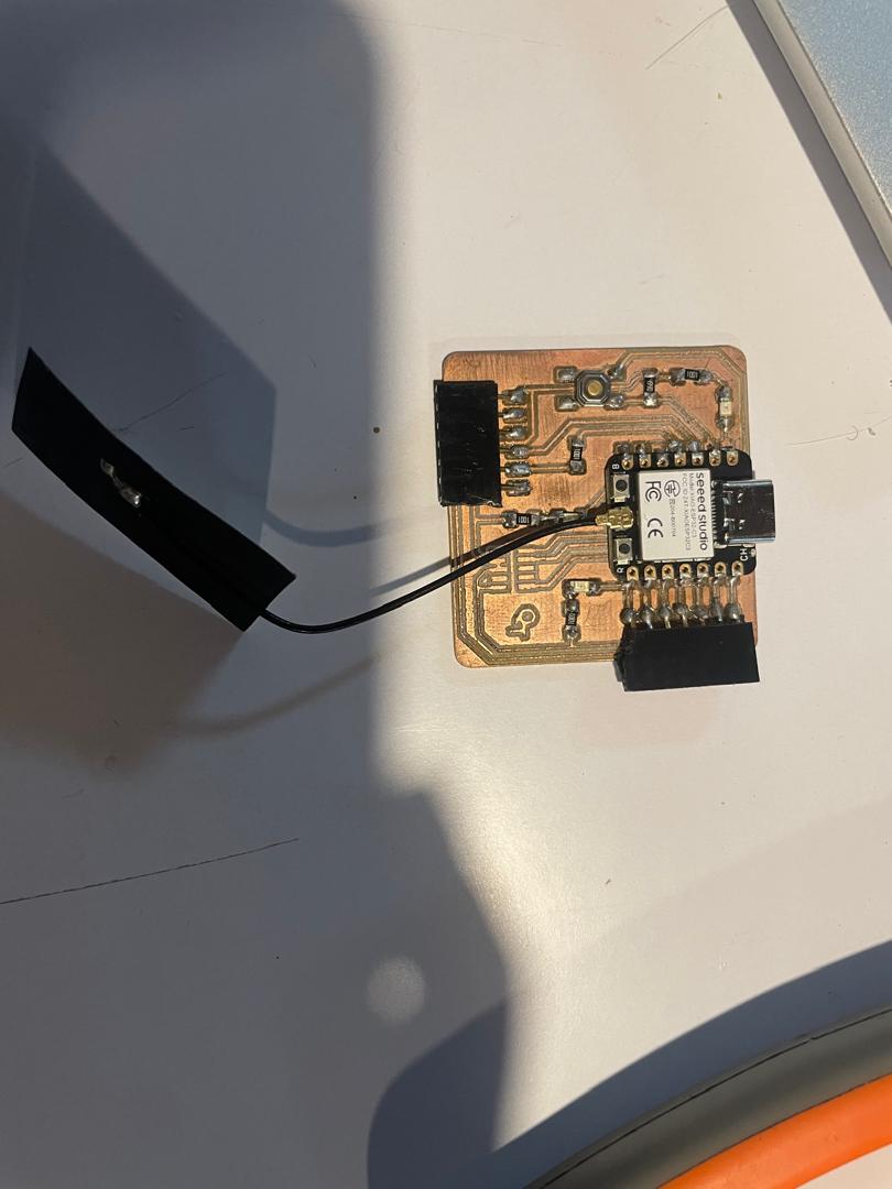
The quentorres is designed for the XIAO RP2040 but, which we don't have. So I used the XIAO ESP32 C3, which has a pinout that works well with the same board. The board was also another print attempt with a lower offset. higher offset numbers make it easier to solder and avoind shortn circuits, but they cost much in time, and the first board and chip were both not working well.
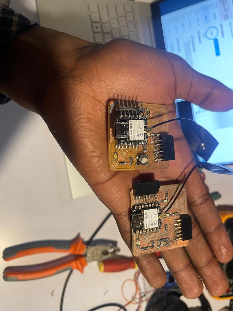
Blink test code
code file: Blink-Test.ino
Contact
Happy to receive your inquiries.
Location:
Kigali, Rwanda
Email:
philemonmail77@gmail.com.com
Call:
+250 780 716 155