
Group Assignment Link here
Gyro system and accelerometer
I selected Gyros as input devices beacause I will use them latter in my final project to control the rocket's whereabouts in the flight computer that I am building.
I am using the Arduino UNO this time to collect information from the Gyro movement siganls. I am using MPU6050 gyroscpe and accelerometer model.
MPU6050 (and MPU6050-Module-Pinout)
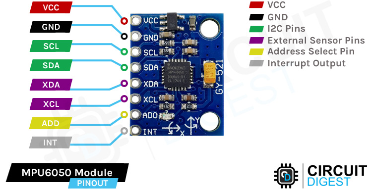
Find the MPU6050 Datasheet Here
I connected the Gyro to an an Arduino Uno; VCC-3V, GND-GND, SCL-SCL, and SDA-SDA. Then the Arduino to my 4 Servo motor board (Only 2 motors work) and Tried different codes to map the gyrocsopes readings (inputs) to signals for the servo (Output).
            #include < MPU6050_tockn.h>
            #include < Wire.h>
            #include < Servo.h>

            int servopin1 = 5;
            int servopin2 = 6;
            int servopin3 = 8;
            int servopin4 = 10;
            Servo servo1;
            Servo servo2;
            Servo servo3;
            Servo servo4;

            MPU6050 mpu6050();
            int16_t ax, ay, az;
            void setup() {
              Serial.begin(9600);
              Wire.begin();
              mpu6050.begin();
              mpu6050.calcGyroOffsets(true);

              servo1.attach(servopin1);
              servo2.attach(servopin2);
              servo3.attach(servopin3);
              servo4.attach(servopin4);
              // put your setup code here, to run once:
            }
            void loop() {
              mpu6050.update();
              if(millis() - timer > 1000) {
                Serial.print("angleX : "); // print
                Serial.print(mpu6050.getAngleX());
                Serial.print("angleY : ");
                Serial.println(mpu6050.getAngleY());
                Serial.print("angleZ : ")  //Added Z axis custom to display in my serial too
                Serial.println(mpu6050.getAngleZ());
                timer = millis();
              }
              //x-axis / roll
            if(mpu6050.getAngleX() == 0){
                servo2.write(90);   //set to 90 degree
              }
                servo2.write(90 - mpu6050.getAngleY()); //unstable angle
                  if(mpu6050.getAngleX() == 0){
                    servo1.write(90);   //set to 90 degree
                }
                servo1.write(90 + mpu6050.getAngleY()); //unstable angle
              // put your main code here, to run repeatedly:
            //y-axis / pitch
                  if(mpu6050.getAngleY() == 0){
                      servo3.write(90);   //set to 90 degrees
              }
                servo3.write(90 + mpu6050.getAngleX()); //unstable angle
                  if(mpu6050.getAngleY() == 0){
                    servo4.write(90);    //set to 90 degrees
                }
                servo4.write(90- mpu6050.getAngleX());
            }
This code, despite beign sophisticated did not work.
And I can't trace back where I got the guide to build this kind of way.
This code was from my outputs assignment but with a few more lines to map the
gyroscope axis reading to different motors to imitate fin motors on a
rocket steering/stabilization that I look forward to in my final project
but it didn't work.
I then consulted Copilot for a code that can serve the same purpose. It suggested a simple code, that I modified to work with my specific motors and arduino pins.
            #include < Wire.h>
            #include < MPU6050.h>
            #include < Servo.h>

            Servo sg90;
            int servo_pin = 5; // Connect the servo to pin 2

            MPU6050 sensor;
            int16_t ax, ay, az;

            void setup() {
                sg90.attach(servo_pin);
                Wire.begin();
                Serial.begin(9600);
                sensor.initialize();
                Serial.println(sensor.testConnection() ? "Successfully Connected" : "Connection failed");
                delay(1000);
                Serial.println("Taking Values from the sensor");
                delay(1000);
            }

            void loop() {
                sensor.getMotion6(&ax, &ay, &az);
                ax = map(ax, -17000, 17000, 0, 180); // Map acceleration values to servo angle
                Serial.println(ax, ay, az);
                sg90.write(ax);
                delay(200);
            }
I could get it to worked this time.
I also realised from reviewing the code with my instructor that it was because in the first program, it wasn't specified that the gyroscope readings have to get written to the servo.
One interesting thing was that though I mapped just the x axis to one motor, one more functioning servo was connected it was picking up signals from the y-axis. I know it's the Y-axis because we tested this gyro with my instructor just after buying and the found the everything works excepting reading Z-axis orientations or motions
The custom board that I am using is built with the ESP32-DEVKIT-V1 chip, designed in the Week8-Electronics-Design
Initially I translated the working code from arduino to ESP32, (basically the libraries)
ESP32 MPU6050 Servo Control
          #include <Wire.h>
          #include <MPU6050.h>
          #include <ESP32Servo.h>

          Servo servoX;
          int servo_pin = 12; // Connect the servo to pin 2

          MPU6050 sensor;
          int16_t ax, ay, az;

          void setup() {
              servoX.attach(servo_pin);
              Wire.begin();
              Serial.begin(9600);
              sensor.initialize();
              Serial.println(sensor.testConnection() ? "Successfully Connected" : "Connection failed");
              delay(1000);
              Serial.println("Taking Values from the sensor");
              delay(1000);
          }

          void loop() {
            //Updating sensor data
              sensor.getAcceleration(&ax, &ay, &az);

              //**********changes/modifications from the arduino code are only below******

            // Map acceleration values to servo angle
              int mapped_ax = map(ax, -17000, 17000, 0, 180);

              //We print the values for debbugging
              Serial.print("ax: ");
              Serial.print(ax);
              Serial.print(" | ay: ");
              Serial.print(ay);
              Serial.print(" | az: ");
              Serial.print(az);

              //Here we going to move the servo
              servoX.write(mapped_ax);
              delay(200);
          }
For a very long time I couldn't understand why the code wouldn't do what I thought it should. since it was clear at the bottom end of the code that the MPU6050 readings should get written to the servos, unlike the very first program.
When I couldn't figure it out, I told Chat GPT to write a code that would achieve the same result.
I found out that using floats is very important for such data, and it was when I got a better idea of what foats are: numbers with decimals.
Basically what the floats helped us was to deal with the math necessary to convert the data into information that the servos can work with in the read write loop we created/desired [void loop()].
The float data type in the code is essential for handling the precise and continuous values resulting from trigonometric functions and for representing the computed angles in degrees. Without float, these calculations would lose precision, leading to incorrect or imprecise servo movements.
              #include < Wire.h>
                #include < MPU6050.h>
                #include < ESP32Servo.h>

                // Define the servos
                Servo servoX;
                Servo servoY;

                // Define the servo pins
                #define SERVO_PIN_X 12
                #define SERVO_PIN_Y 27

                // Create an instance of the MPU6050
                MPU6050 sensor;

                // Variables to store the MPU6050 readings
                int16_t ax, ay, az;
                int16_t gx, gy, gz;

                // Setup function to initialize the MPU6050 and servos
                void setup() {
                    // Attach the servos to the defined pins
                    servoX.attach(SERVO_PIN_X);
                    servoY.attach(SERVO_PIN_Y);

                    // Initialize I2C communication
                    Wire.begin();

                    // Initialize serial communication for debugging
                    Serial.begin(115200);

                    // Initialize the MPU6050 sensor
                    sensor.initialize();

                    // Check if the MPU6050 is connected successfully
                    if (sensor.testConnection()) {
                        Serial.println("Successfully Connected to MPU6050");
                    } else {
                        Serial.println("Connection failed");
                    }

                    // Provide some delay for stability
                    delay(1000);
                }

                // Loop function to read the MPU6050 data and control the servos
                void loop() {
                    // Read the acceleration and gyroscope data from the MPU6050
                    sensor.getMotion6(&ax, &ay, &az, &gx, &gy, &gz);

                    // Calculate the rotation angles (pitch and roll)
                    float pitch = atan2(ax, sqrt(ay * ay + az * az)) * 180.0 / M_PI;
                    float roll = atan2(ay, sqrt(ax * ax + az * az)) * 180.0 / M_PI;

                    // Map the pitch and roll angles to servo angles
                    int servoAngleX = map(pitch, -90, 90, 0, 180);
                    int servoAngleY = map(roll, -90, 90, 0, 180);

                    // Write the mapped angles to the servos
                    servoX.write(servoAngleX);
                    servoY.write(servoAngleY);

                    // Print the angles for debugging
                    Serial.print("Pitch: ");
                    Serial.print(pitch);
                    Serial.print(" | Roll: ");
                    Serial.print(roll);
                    Serial.print(" | ServoX: ");
                    Serial.print(servoAngleX);
                    Serial.print(" | ServoY: ");
                    Serial.println(servoAngleY);

                    // Provide some delay to control the update rate
                    delay(200);
                }
Contact
Happy to receive your inquiries.
Location:
Kigali, Rwanda
Email:
philemonmail77@gmail.com.com
Call:
+250 780 716 155