
Design tool: KiCAD
Group_Assignment: Electrinics Design
We had an indepth session with our instructor on KiCad: Importing models (boards), adding electronics to your designs, and more. But first we installed it, obviously.
.png)
We went to preferences, manage symbol librairies and imported the XIAO libraries to then use in further designs.
.png)
.png)
It was my first time with KiCad, so it was a bit confusing where to find stuff, because I also couldn't do the whole session with my classmates and instructor.
I did some practice trying to replicate the Quentores. I put the image aside and attempted tracing the connections and played with the components/symbols library to find similar resistors, connectors, and LEDs but with the XIAO SAMD23.
.png)
Latter after I had a better idea of how things work with Kicad and set off to design a custom board that I will use latter to connect and interact with my servo motors with the ESP32 C3 Quentores.
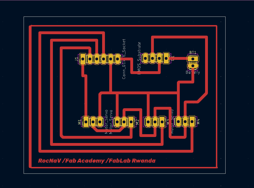
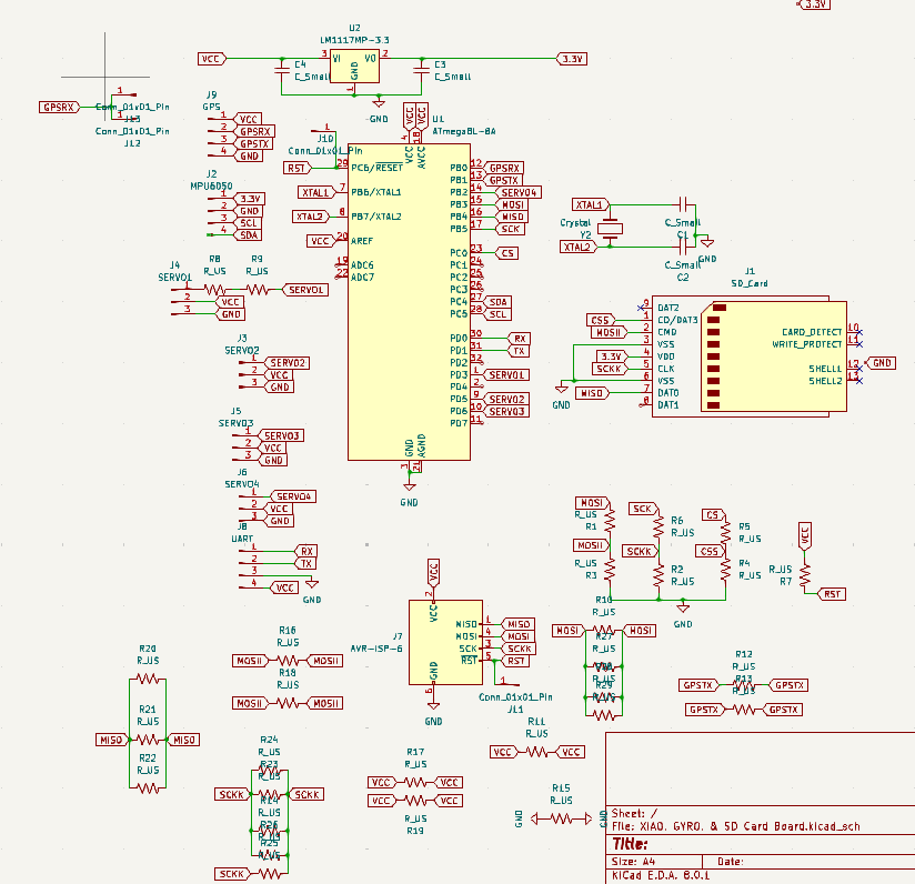
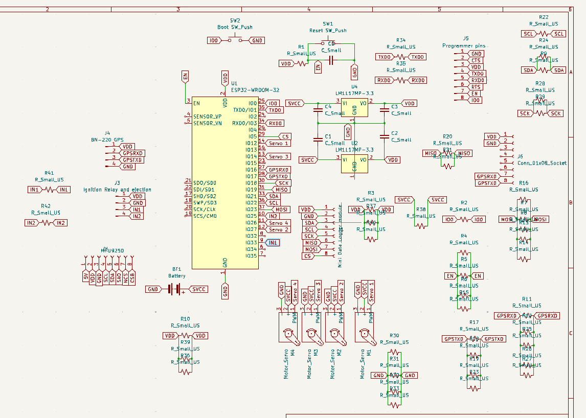
My new board is supposed to host 4 servo motors, a mosfet, a battery, and an interface with the XIAO (J1) and play around with setting motions to them. J1 has 4 PWM terminals (pin outs) to receive signal form the XIAO, 1 pin out for all the motor groungs to The XIAO, and the another for the mosfet's ground. All the motors positive terminals meet before they all go to the mosfet's source, while the motor grounds all go to the Battery's as well (because they also went to the XIAO). Finally the mosfet's drain is going to battery positive, which allows to use a switch in our control system for the motors (It's also connected to the Xiao and motors in a structure mentioned above). See the schematic below
.png)
.png)
.png)
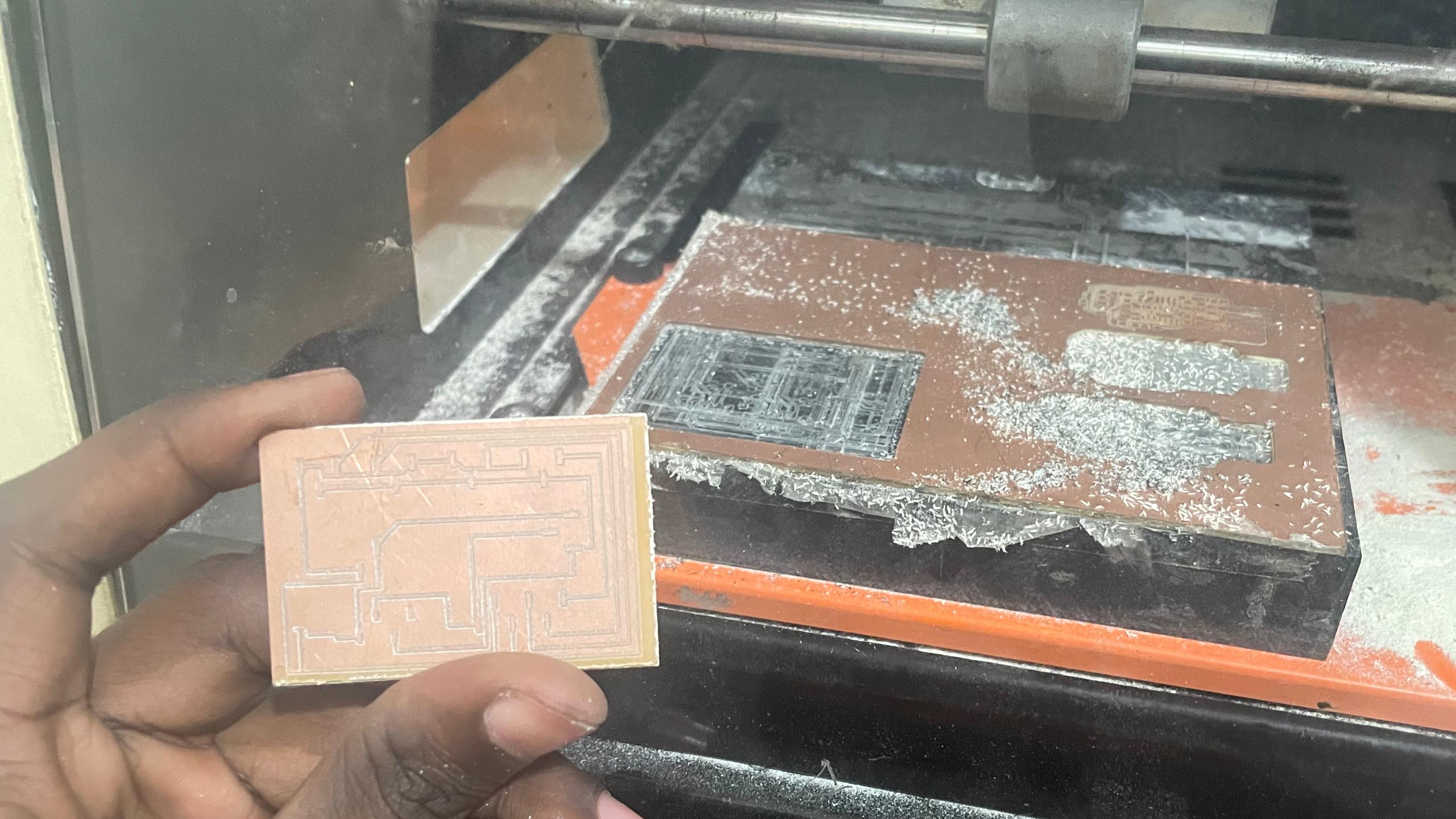
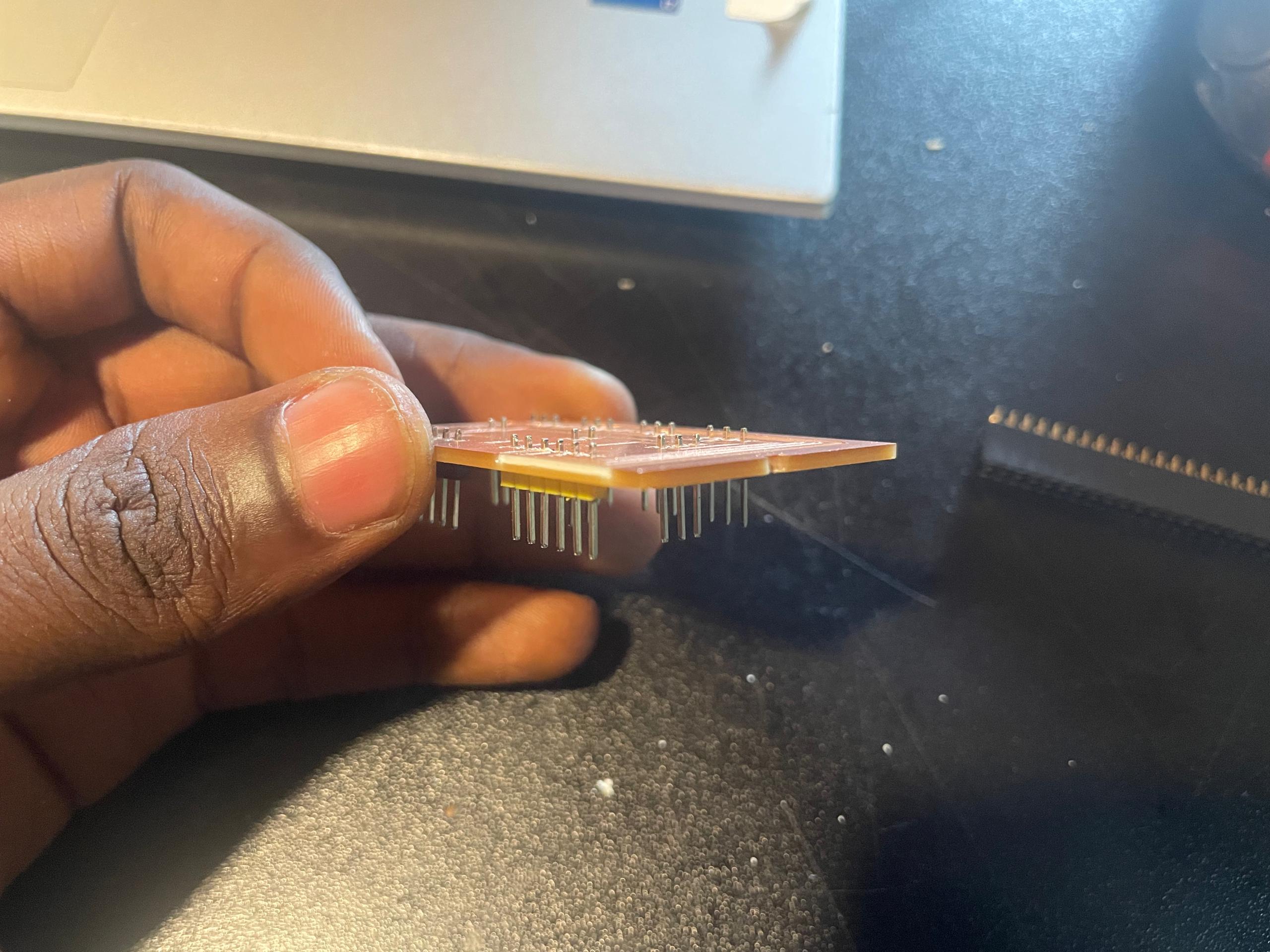
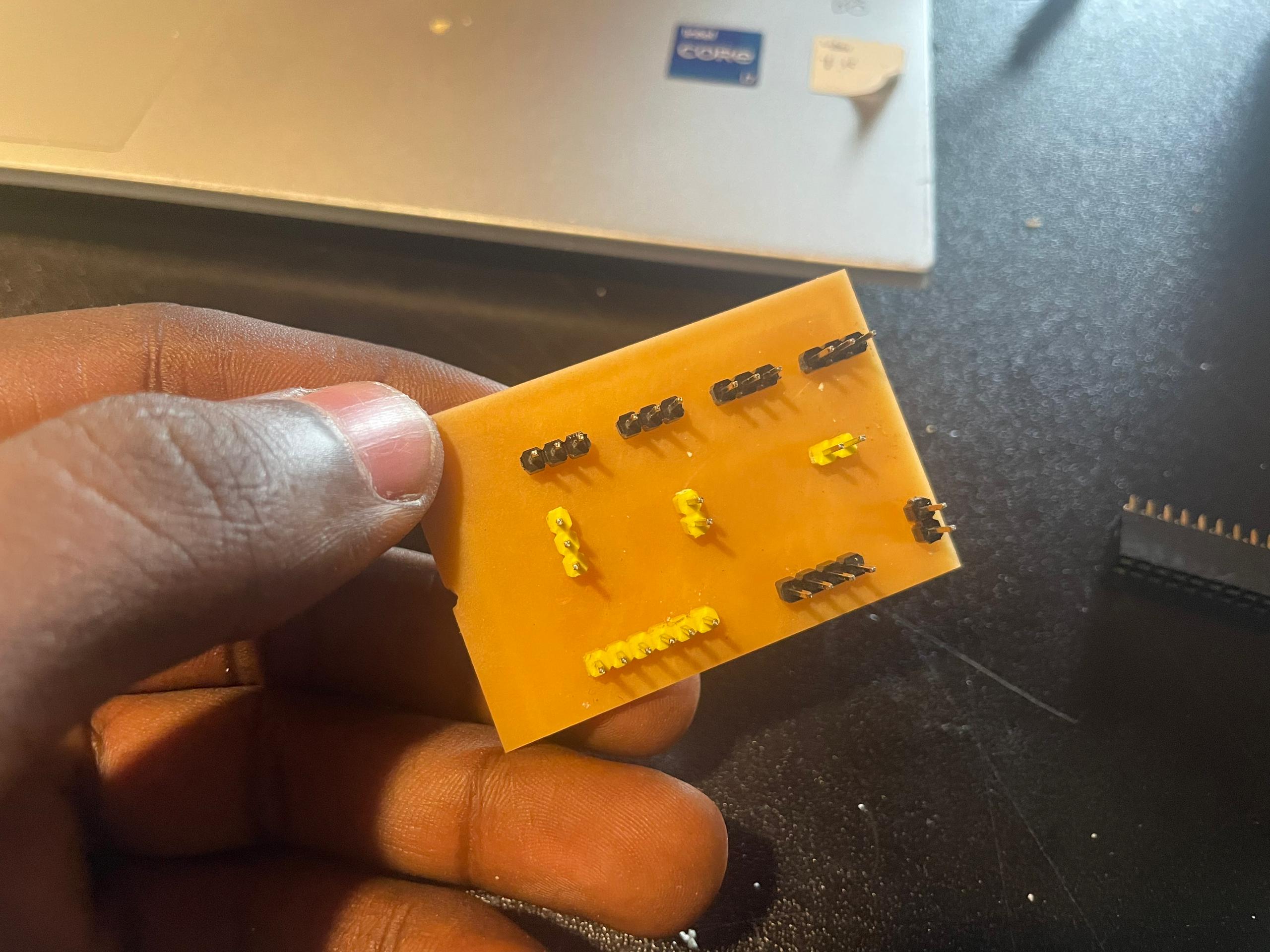
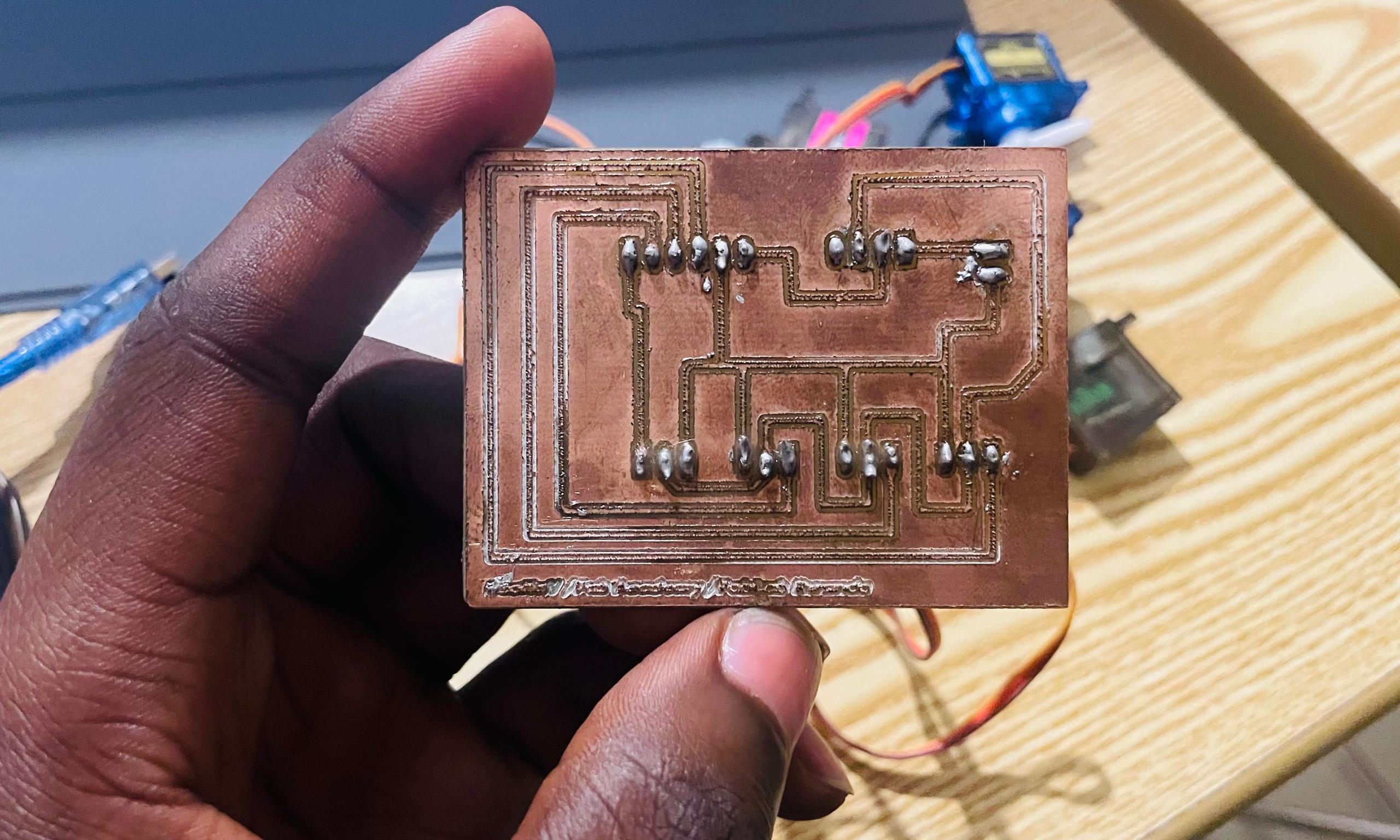
After printing my board I realized soldering aluminium pinheaders on the board (They don't easily as bronze), I then redisigned the board and featured through holes to make drills at the connection zones.
.png)
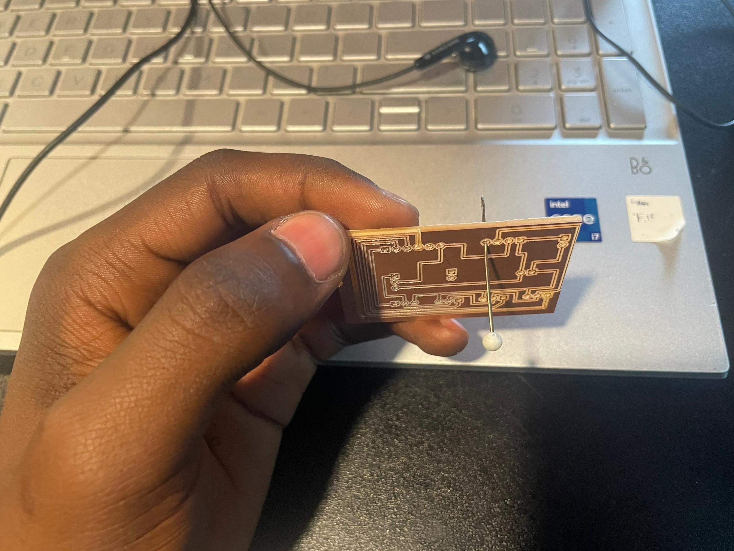
I Printed it, then drilled halfway through because the Vbit I had a bigger diameter and could erase the copper layer on the sides of the drills if it went much deeper. I did the rest of the drilling by hand with a superglue pin. The whole goal was to make it ease to secure my connectors in the board, so that they don't easily drop out when I solder them latter (my soldering still makes weak connections at the moment, so I am trying different technics to help my boards hold on to the connectors)
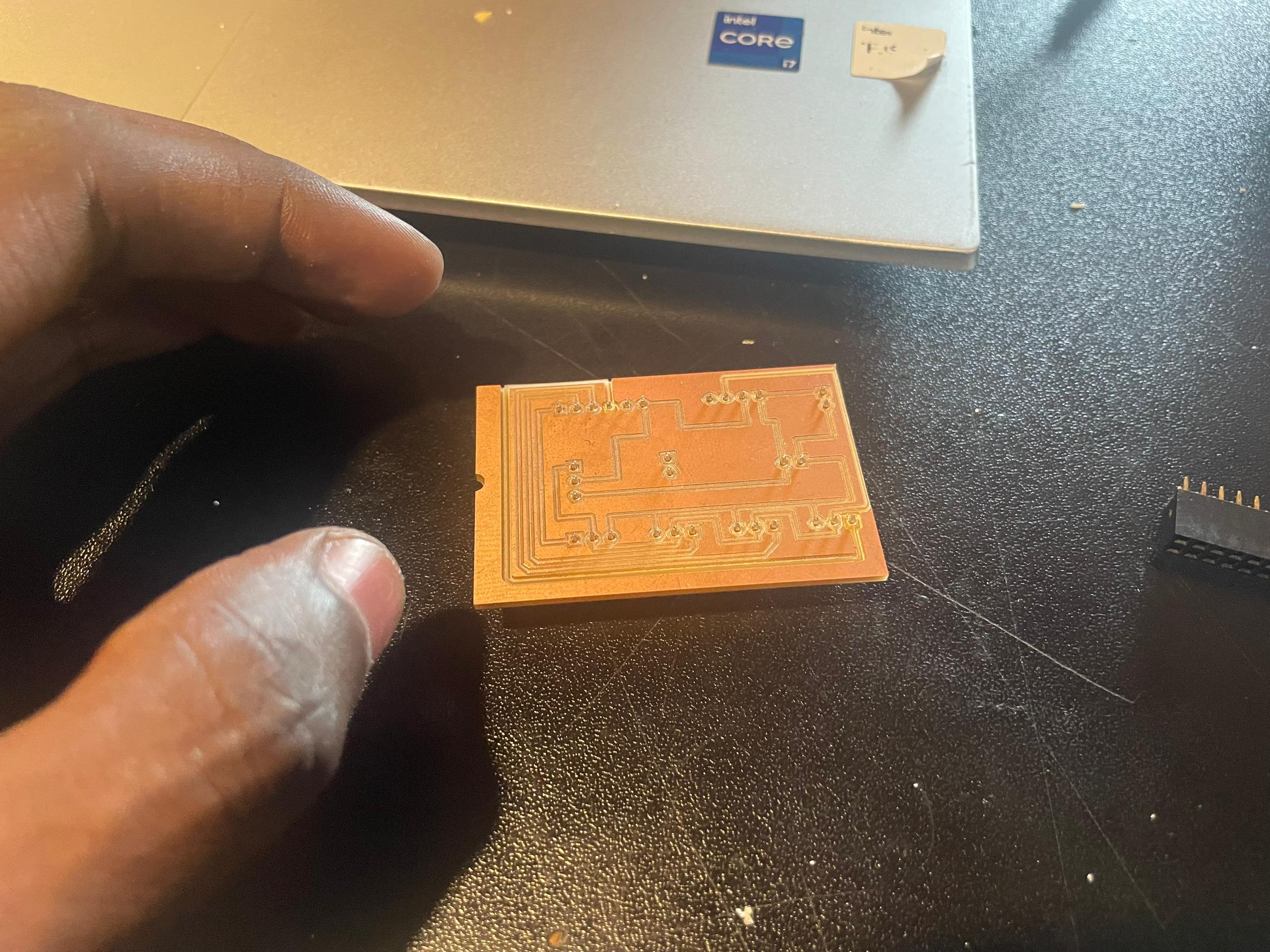
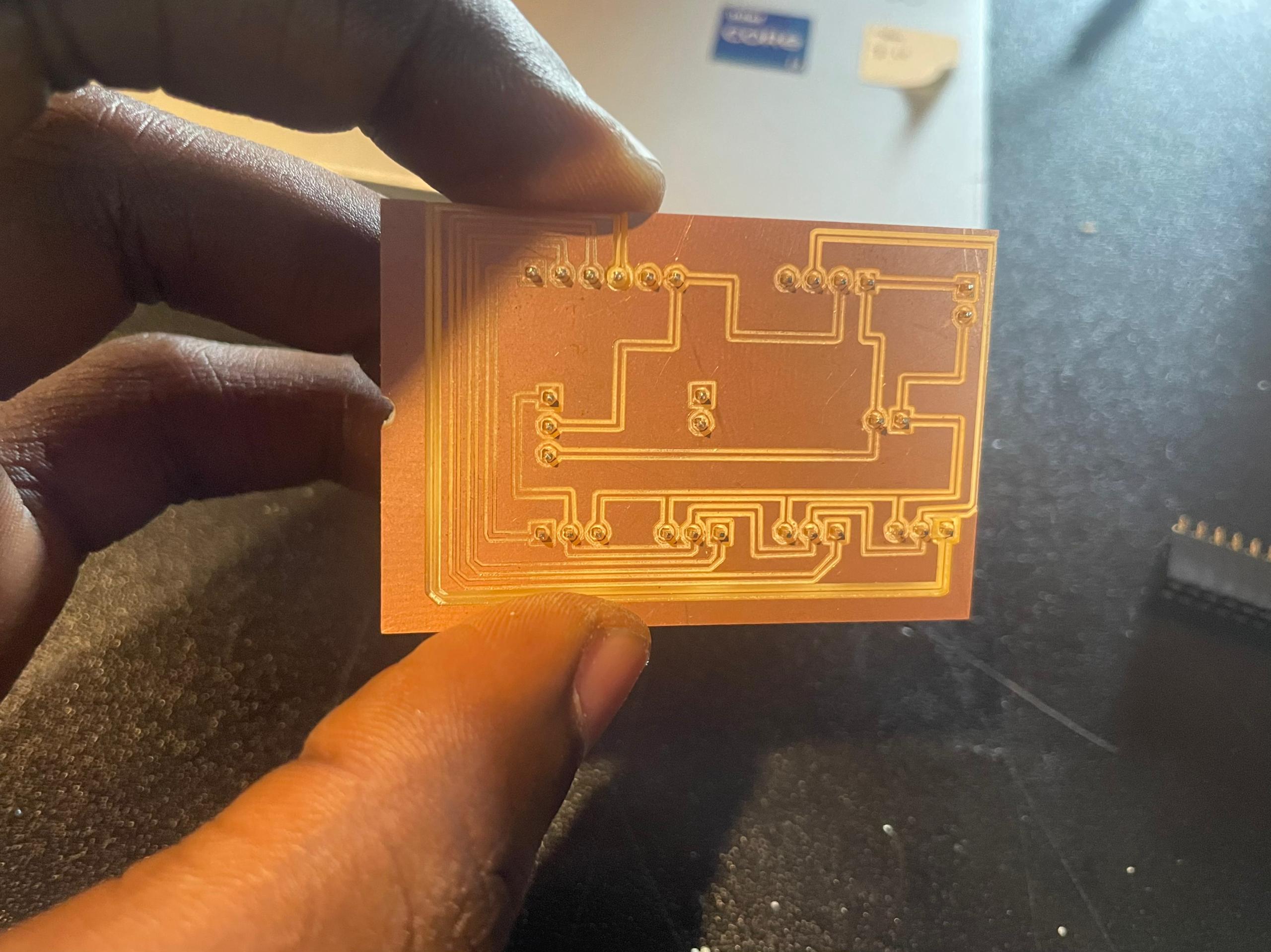
I latter made upgrades to the board design, printed it again for more projects that will involve motors
I realised I have to build a micro-controller board, not just any board.
So I took the opportunity and started to work on a Final project's board. I went through a lot of different versions before I reached the model we are currently using.
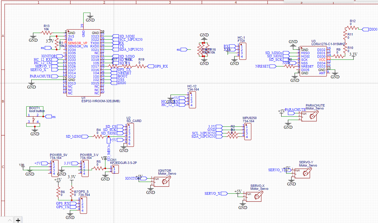
Regardless of the micro-controller I use, I wanted the board to have/be a integrated system (with a program on it) that can monitor the rocket's behavior, know where it is (Navigation), and allow us to control some physical subsystems on the rocket.
Essential components
Information Processor: we explored both AT-MEGA328PU and the ESP32-DEVKIT-V1
Data logger: SD-Card
Gyroscope and Accelerometer
GPS
Communication Module: NRF, LoRA, Zigbee, and more trys
And SERVOs to steer the rocket (Extra feature): Thrust Vectored Control
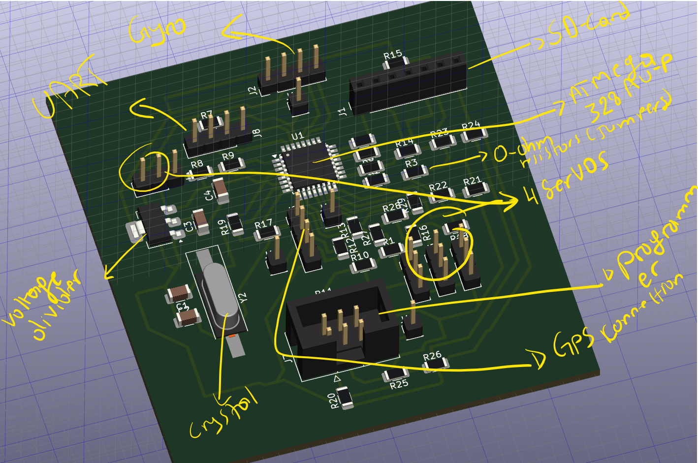
The first model was build around the AT-MEGA328p-AU shown below:
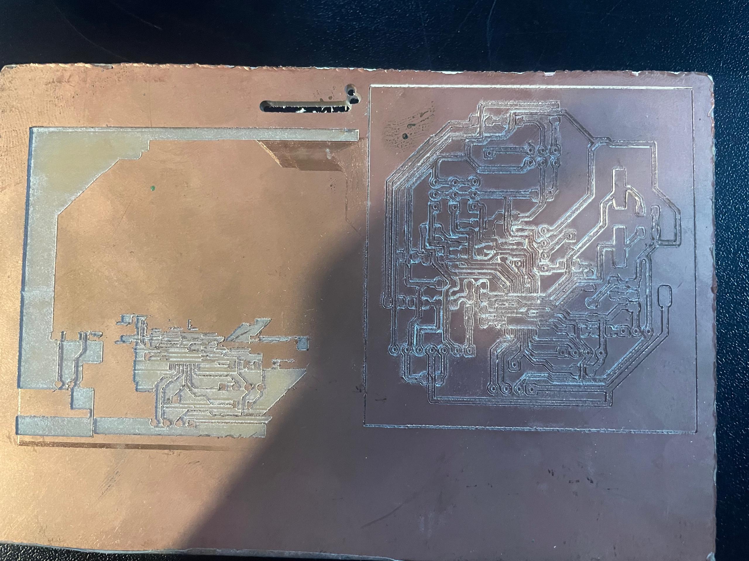
We printed this model a lot of times, but couldn't get it to come out good.
Finally we had a successful attempt. This was after we realised the tool was really old nad broken, and replaced it. We also found it very hard to solder, and decided to move on to a different chip.
Design Files
linked above
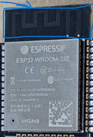
ESP32-WROOM/ESP32-DEVKIT-V1 Chip
We went for this chip for a couple of reasons:
It has built-in wifi, a more spaced footprints, and we didn't have either this chip or the ATMEGA, we were about to purchase more electronics at our Fablab.
So I went in Kicad and design a new PCB from the ground up. I enjoyed regardless of all the work and time it was costing me in the grand scheme of the Fab Academy (I wanted to master it).
I designed a box for it as well but lost it amidst an accident (1.5Kg Rocket fuel caught fire in our lab and we lost a few stuff in the craziness).
.png)
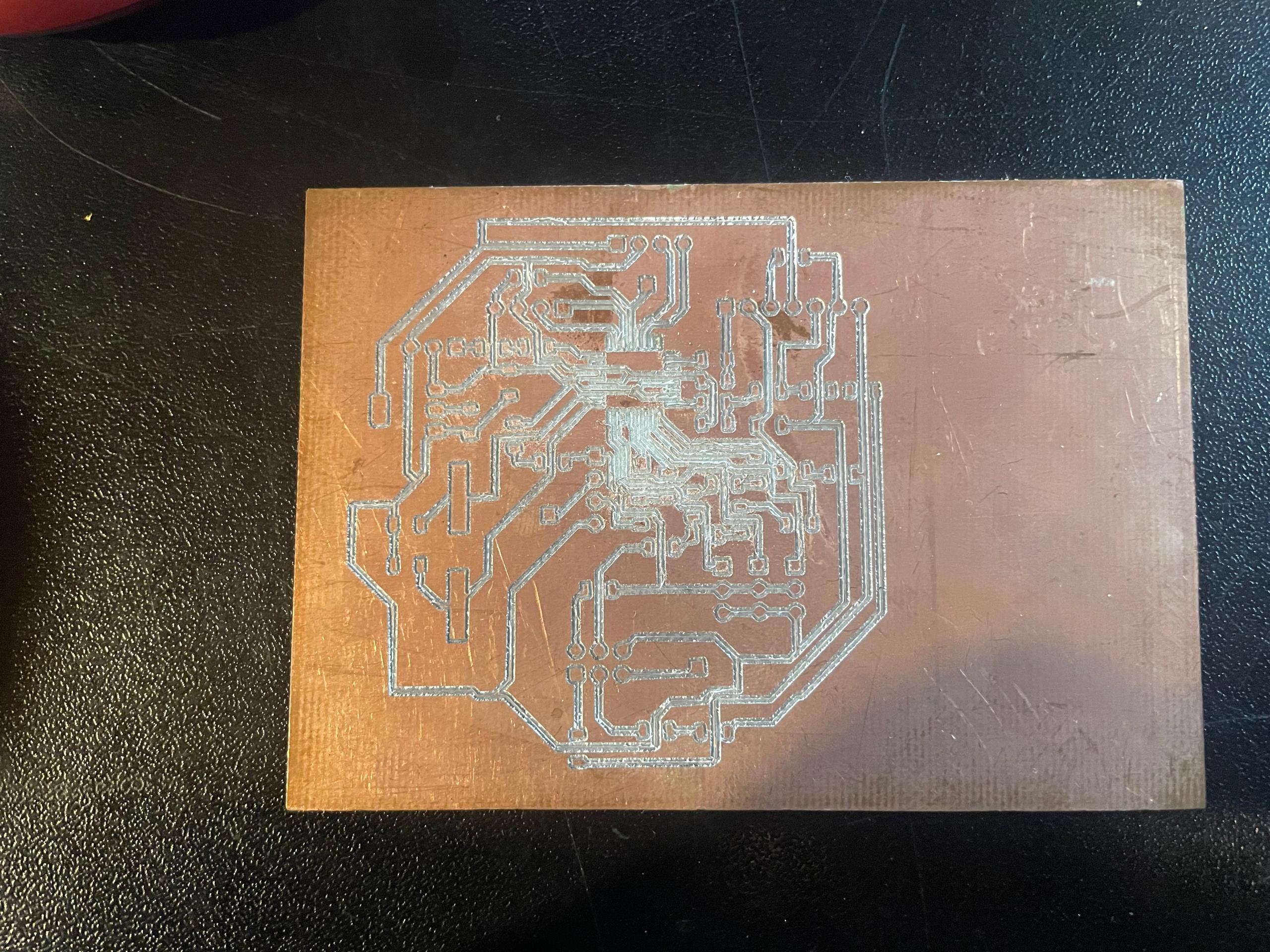
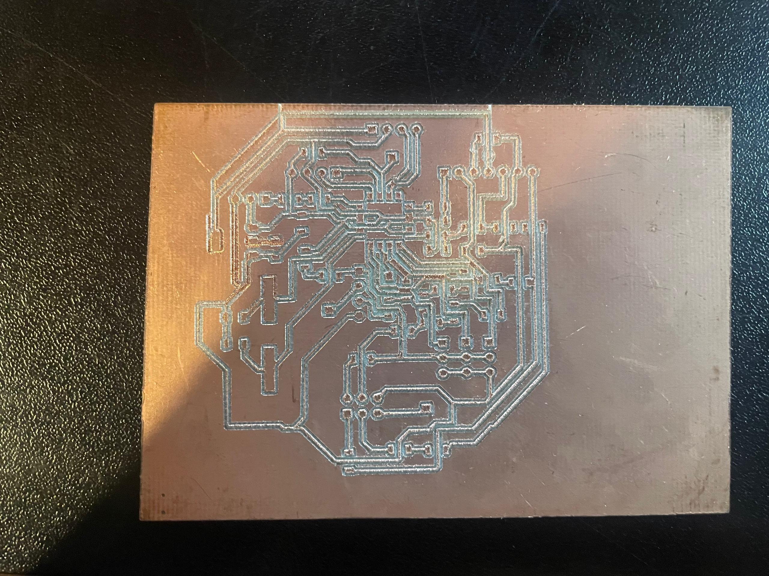
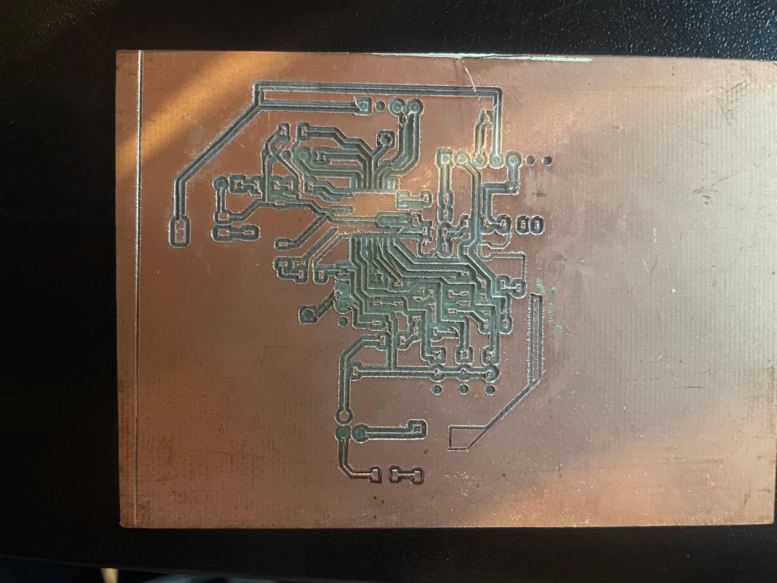
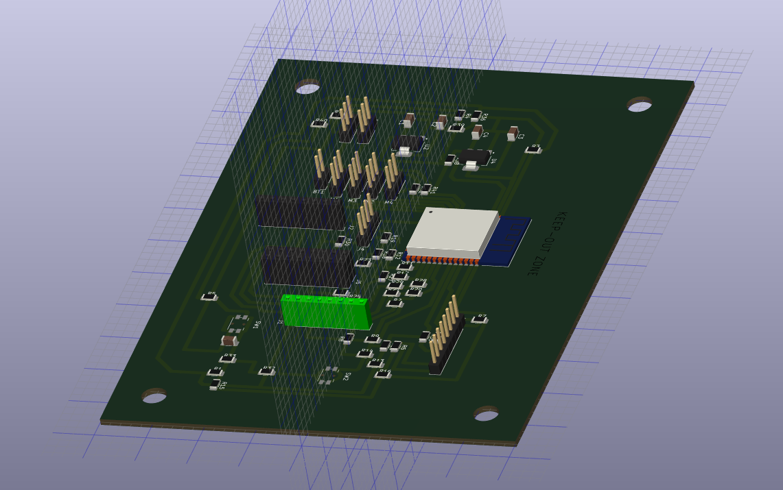
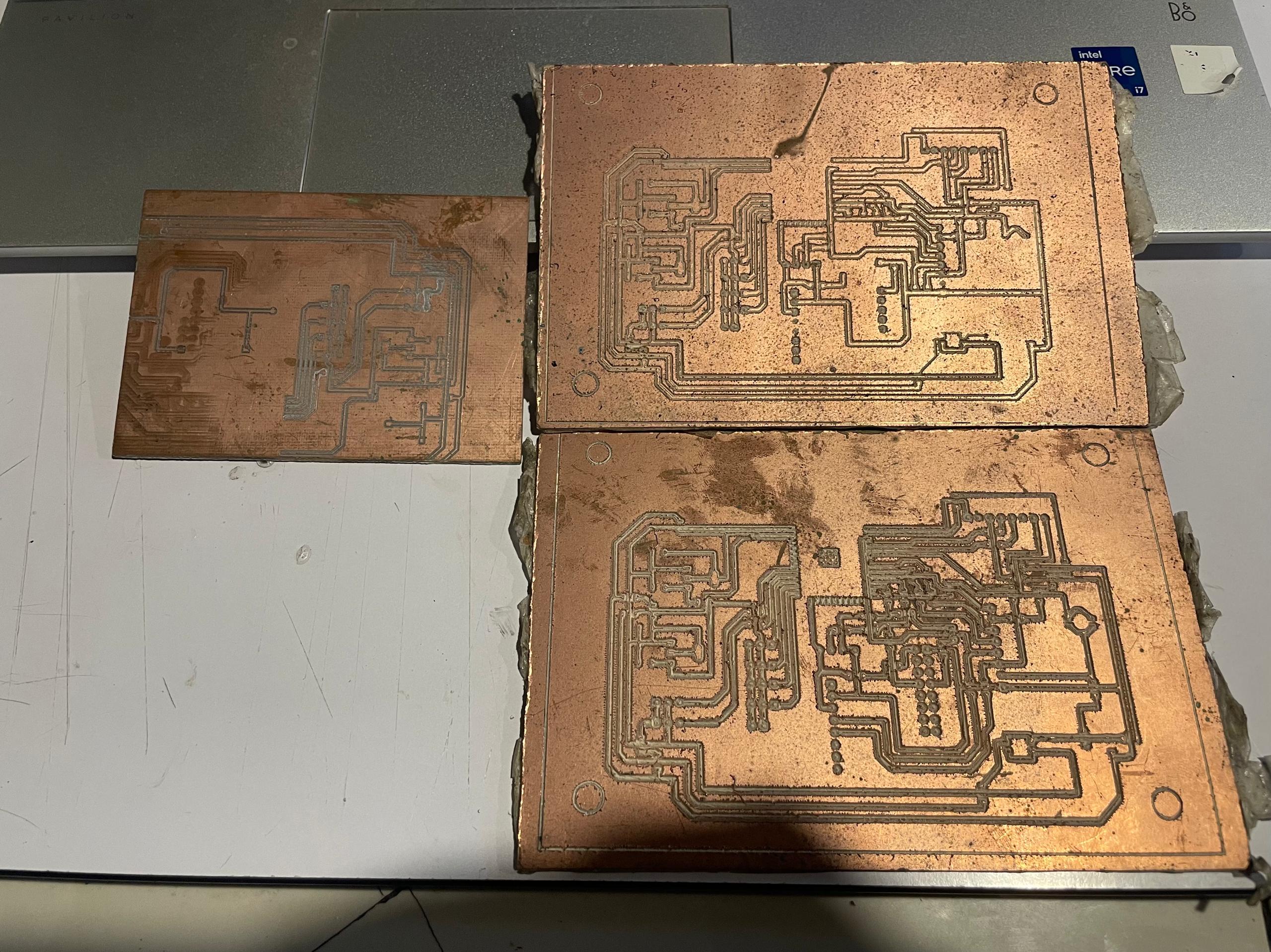
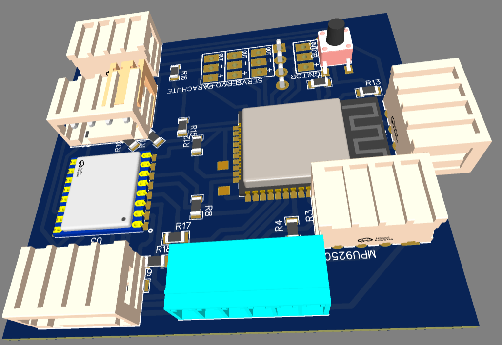
A few prints of this version below:
The model was basically good to go, but it was too big to fit inside our rocket (version1 and version2[which was even a smaller rocket]), so design was havily modified with my instructor Lambert, and this time we rebuilt it again from EasyEDA.
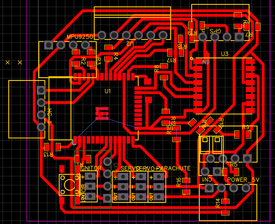
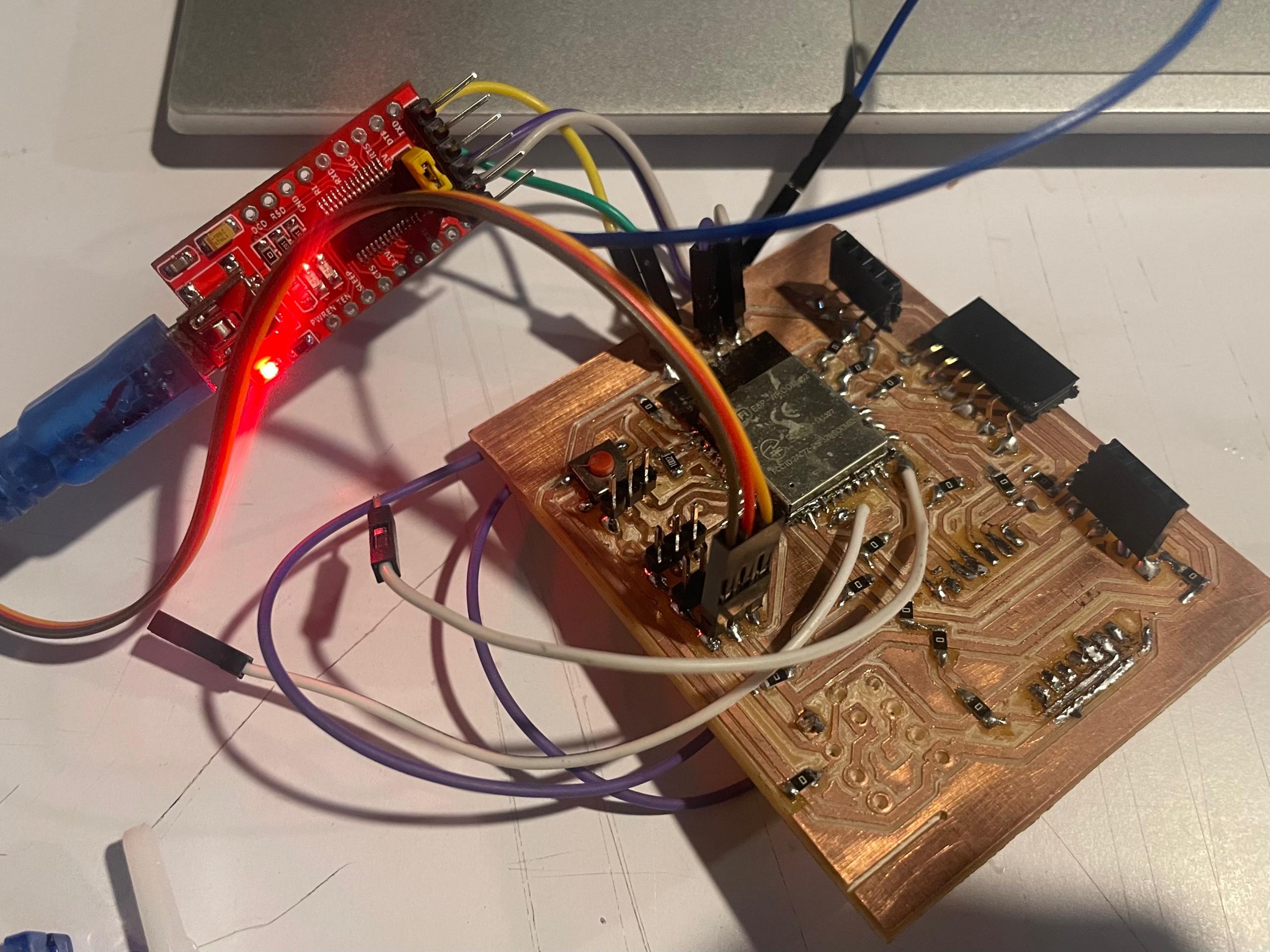
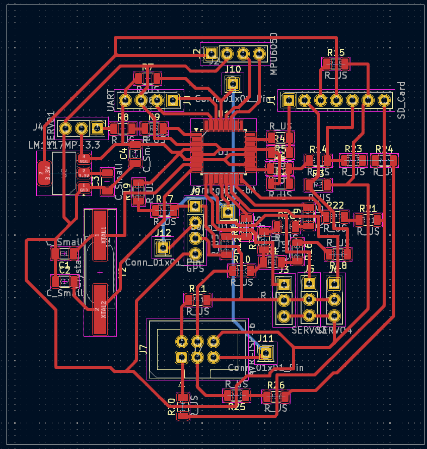
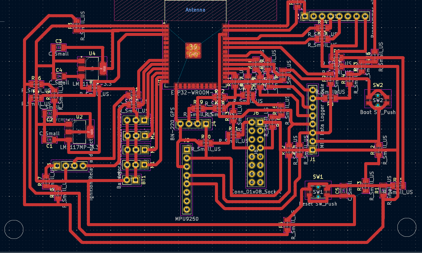
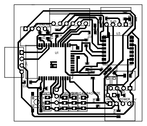
PNG of the PCB
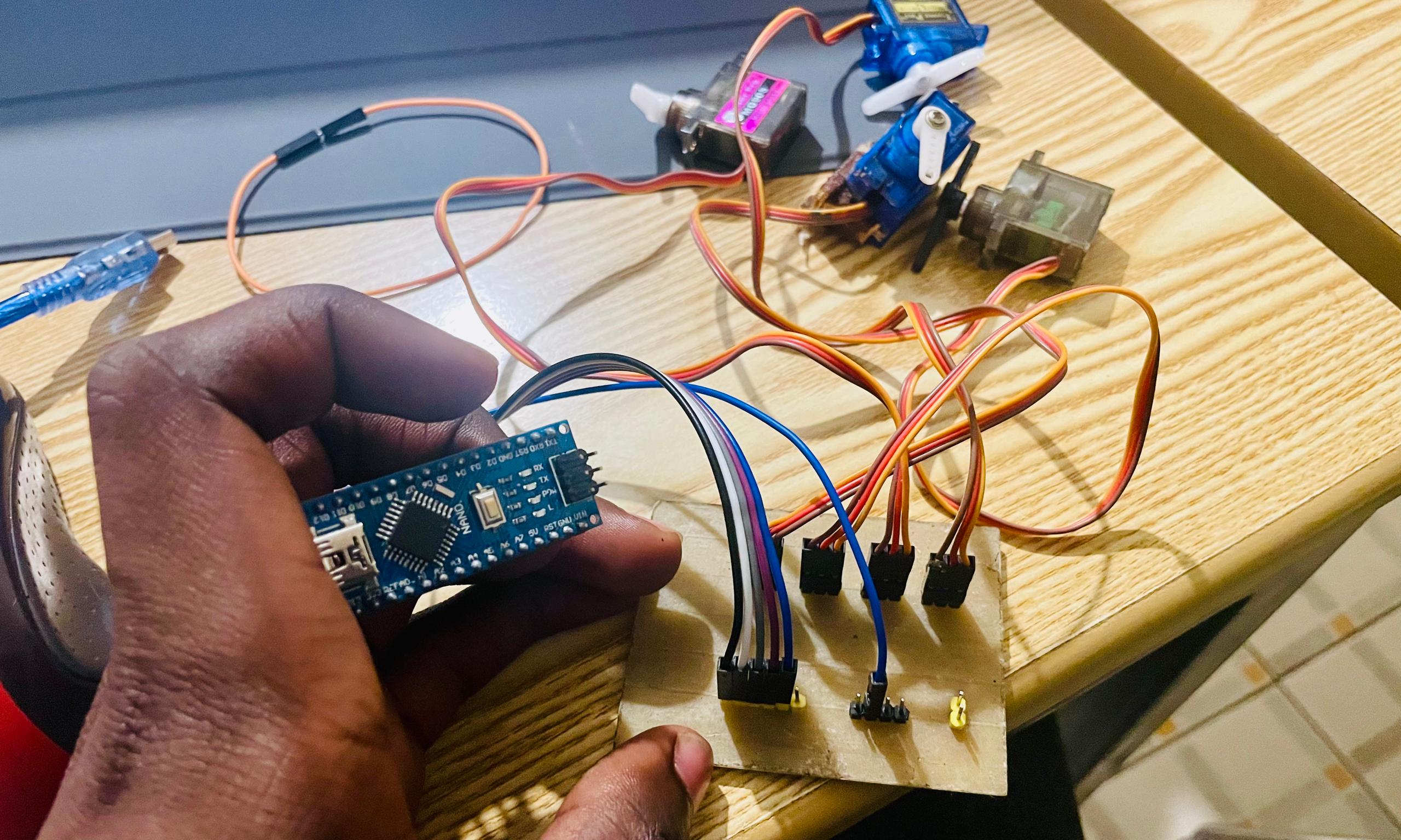
A simple test of servo controls with the board
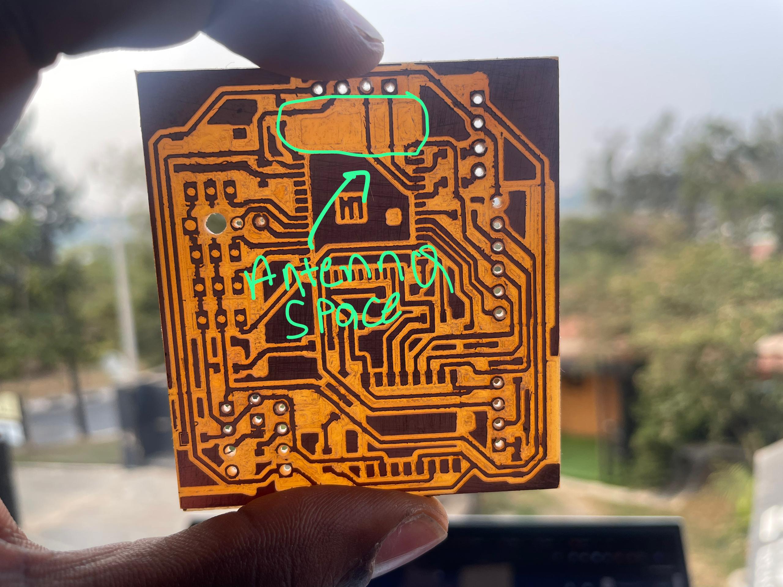
If you are going to be using your board with wireless programs, you want to remove the copper beneath the antenna to eliminate electromagnetics inconsistencies that can lead to noise or misbehaviour of the ESP built in antenna.
Contact
Happy to receive your inquiries.
Location:
Kigali, Rwanda
Email:
philemonmail77@gmail.com.com
Call:
+250 780 716 155