Display Words / Graph / Motion with TFT Display
Write something at the front
Written on 5.12nd, since I want to do a protable module and when it attach to the reComputer it will automatically transfer data. I think it would be great that there are some animation can display at the same time, during the data transmittion.
The idea of mine is that:
I can see the feedback in real time when I plug in my portable module in my reComputer, which it can tell that my controller(XIAO Board) is working.
Hardware I am going to use
I am going to use the hardware below:

Why I am using XIAO ESP32C3 is that it can offer wireless connectivity(Wi-Fi/Bluetooth) and it is good for my final project, as well as it is powerful enough to drive multiple images display.
XIAO ESP32C3
Actually I have brought two TFT displays:
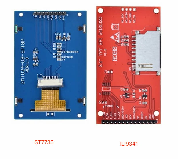
Because I am not familiar with TFT displays and heart that there are two types of the drivers:
- ST7735
- ILI9341
According to other people's opinions, there aren not so many differences between these two. But the ST7735 appears to be superior in spi communication rates.
Notes about Thin Film Transistor-Liquid Crystal Display(TFT Display)
The theory about TFT display is important. It will help me understand how to wirte my code.
The features:
- High resolution: commonly used embedded TFTLCD screen resolution is 320* 480, 480 * 320, 800 * 480, 1024 * 600 and so on
- Rich color: TFTLCD supports colors RGB565, RGB666 and RGB888
- Abundant operation interfaces: TFTLCD supports parallel port 8080, serial port SPI, 12C and other communication protocols
- With touch screen: TFTLCD can be connected to the external touch chip to achieve the effect of touch screen.
For mine: my TFT displays are both QVGA(240x320), using SPI communication, displaying 16BIT RGB 65K(RGB565), and not with touch function.
Since the Display itself is only a screen, only responsible for the display of images, its internal is not the function of storing image data, this part of the function is provided by the LCD driver chip(like previous: ST7735 and ILI9341). Thus, take my ST7735S display as an example:
The ST7735S divides the inventory into 240*320 grids. There are a total of 76800 cells, each representing a pixel, all the pixels combine for an image/word - This will be the Video memory structure.
The the scanning mode of TFTLCD pixels are scanned from left to right and from top to bottom. Of course, users can also modify the scanning direction of pixels by configuring the MV MX MY register bits:
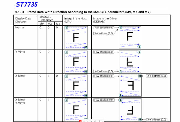
This is reference from Sitronix ST7735 Official.
For drving the display(with driver chip) with MCU:
- For the video memory storage structure of ST7735S, the MCU needs to read out the video memory data of ST7735S every time it changes the data to ensure that the old data does not conflict with the new data.
- At the same time, in practical applications, a two-dimensional array with the size of 240*320 2 is generally defined in the MCU, which can be regarded as the external video memory of ST7735S.
- Every time the data needs to be updated, the external video memory will be updated, and finally the entire video memory data will be refreshed to the internal ST7735S by command.
Since there are no character/words/images libraries in the ST7735S, when I need to display characters or other things on the LCD, I need to make my own character library first, and display the data in the libraries to the LCD screen by calling.
There are multiple ways to bulid the libraries(images/words to lcd)
- pctolcd2002 software - English character modulo and Chinese character modulo
- img2lcd - Convert BMP, BIN and other images to color LCD format
- Online one like: LVGL Converter; image2cpp
Hardware Connection
For the SPI communication, I ask GPT to output a diagram for me:
| TFT Display Pin | Description | Suggested MCU Pin |
|---|---|---|
| SCK (Clock) | Clock signal for SPI | 13 (or other SCK pin) |
| MOSI (SDA) | Master Out, Slave In for SPI | 11 (or other MOSI pin) |
| MISO (SDO) | Master In, Slave Out for SPI | 12 (only if data read is needed) |
| CS (Chip Select) | Chip select for SPI | 10 (or other available digital pin) |
| DC (Data/Command) | Data/Command control signal | 9 (or other available digital pin) |
| RESET | Reset pin | 8 (or other available digital pin) |
| BL (Backlight) | Backlight control | Connected to 3.3V or 5V through a resistor |
| VCC (Power) | Power supply (3.3V or 5V) | 3.3V or 5V (depending on display requirements) |
| GND (Ground) | Ground | GND |
This is for the general and it might be little different giving different displays.
I then check the XIAO ESP32C3 Pin diagram.
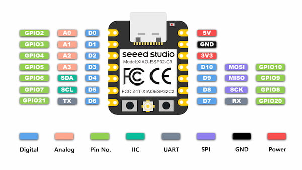
Finally I have my own connections:
| TFT Display Pin | Description | Connected Xiao Pin |
|---|---|---|
| VCC (Power) | Power supply (3.3V) | 3V3 on the Xiao |
| GND (Ground) | Ground | GND on the Xiao |
| CS (Chip Select) | Chip select for SPI | D0 on the Xiao |
| BL (Backlight) | Backlight control | D1 on the Xiao |
| DC (Data/Command) | Data/Command control signal | D2 on the Xiao |
| RESET | Reset pin | D3 on the Xiao |
| SCL (Clock) | Clock signal for SPI | D8 (SCK) on the Xiao |
| SDA (MOSI) | Master Out, Slave In for SPI | D10 (MOSI) on the Xiao |
Software testing
I am going to test two displays, but first I need to set my software right. I am planning to use Arduino:
Arduino IDE Setup
- I download the Arduino software on the official website
- I launch the Arduino application.
- I navigate to
Arduino IDE->Preferences(beacsue my recomputer is MAC), and fill Additional Boards Manager URLs(XIAO ESP32C3) with the url below:
https://raw.githubusercontent.com/espressif/arduino-esp32/gh-pages/package_esp32_index.json
- I then navigate to the
Boards Manager..., type the keyword "ESP32" in the searching blank. Select the lastest version of "esp32" and install it.
Libraries Setup
For using these two, there are additional Arduino libraries required:
- ST7735 Arduino Library(for driving ST2275)
- ILI9341 Arduino Library(for driving ILI9341)
- Adafruit-GFX-Library(general)
I download the .zip files and navigate to Sketch > Include Library > Add .ZIP library to search the library.
Now the hardware and software part are both done, I can get started.
The common functions by Libraries
- Initialize display - Set the initial status of the display, including the screen orientation and color mode.
tft.init(240, 240); // initialize a ST7789 chip, 240x240 pixels
different chip done by differnent one
- Clear screen - Clear the contents of the display, usually set to a specific color, such as black or white.
tft.fillScreen(ILI9341_BLACK);
- Ports setup
#define TFT_CS     A0
#define TFT_RST    A2
#define TFT_DC     A1
#define TFT_MOSI   10
#define TFT_CLK    8
#define TFT_LED    A3   // 如果不控制背光,可以忽略这个引脚或始终保持为HIGH

// 初始化Adafruit ILI9341
Adafruit_ILI9341 tft = Adafruit_ILI9341(TFT_CS, TFT_DC, TFT_RST);
 // for the initial
- Basic Graph
tft.drawPixel(10, 10, ILI9341_WHITE); // 绘制一个白色像素点
tft.drawLine(0, 0, 50, 50, ILI9341_RED); // 绘制一条红色直线
tft.drawRect(10, 10, 50, 50, ILI9341_GREEN); // 绘制一个绿色矩形框
tft.fillRect(70, 70, 60, 60, ILI9341_BLUE); // 绘制一个填充的蓝色矩形
- Basic Text
tft.setCursor(20, 20); //position
tft.setTextColor(ILI9341_WHITE);  // color
tft.setTextSize(2); //size
tft.println("Hello World!"); //text
ST7735 testing(not very well)
I have uploaded the code below, from the example:
#include <Adafruit_GFX.h>    // Core graphics library
#include <Adafruit_ST7735.h> // Hardware-specific library for ST7735
#include <SPI.h>

// 定义 XIAO ESP32C3 与 TFT 显示屏的引脚连接
#define TFT_CS   D0  // Chip select
#define TFT_RST  D3  // Reset pin
#define TFT_DC   D2  // Data/command pin
#define TFT_BL   D1  // Backlight pin

// 使用硬件 SPI 初始化 Adafruit_ST7735 库
Adafruit_ST7735 tft = Adafruit_ST7735(TFT_CS, TFT_DC, TFT_RST);

void setup() {
  pinMode(TFT_BL, OUTPUT);
  digitalWrite(TFT_BL, HIGH);  // 打开背光

  tft.initR(INITR_BLACKTAB);   // 初始化显示屏,具体的型号可能需要调整
  tft.setRotation(3);          // 设置显示方向,根据你的需求调整(0-3)
  tft.fillScreen(ST77XX_BLACK);   // 清屏,使用黑色填充屏幕

  tft.setTextColor(ST77XX_RED);   // 设置文字颜色为红色
  tft.setTextSize(2);             // 设置文字大小,调整为 2 以增大文字
  tft.setCursor(0, 0);            // 设置文字的初始位置
  tft.println("Hello, World!");   // 显示文字,使用 println 以换行
}

void loop() {

}
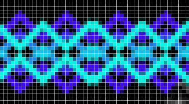
The output is not good. I change the tft.setRotation and tft.setTextSize and tft.setTextColor and it show up like this:
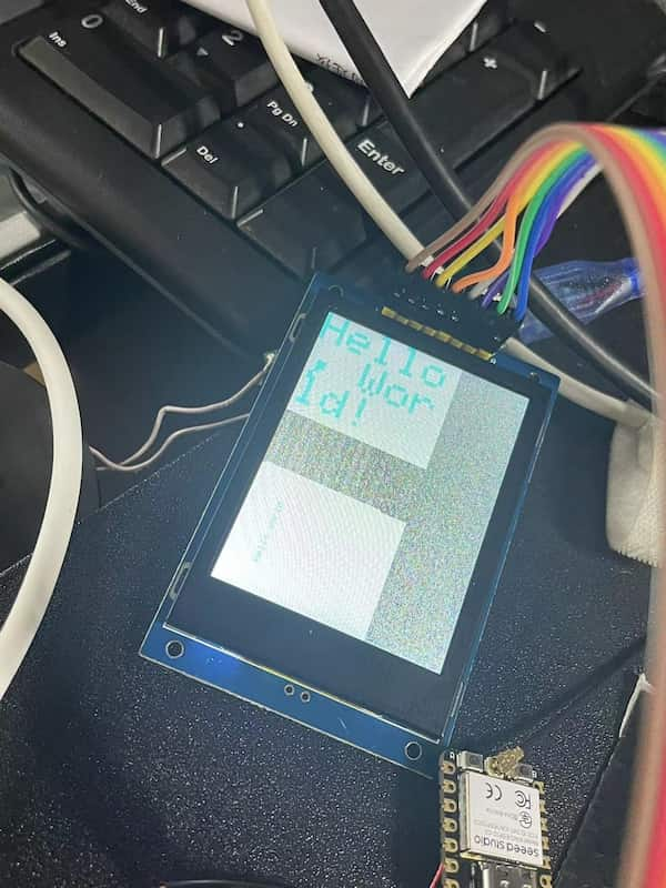
Which shows like there is just a small portion of the screen is showing, and the color is wrong. This is not good. I ask for help and got these answers:
- The parameters for initializing the display are not set correctly
- The physical connection is faulty, or solder problem
- The SPI communication speed is too fast
I will get to it later.
ILI9341 testing(works fine)
I have uploaded the code below, from the example:
#include <SPI.h>
#include <Adafruit_GFX.h>    // Core graphics library
#include <Adafruit_ILI9341.h> // Hardware-specific library

// 定义使用的引脚
#define TFT_CS     A0
#define TFT_RST    A2
#define TFT_DC     A1
#define TFT_MOSI   10
#define TFT_CLK    8
#define TFT_LED    A3   // 如果不控制背光,可以忽略这个引脚或始终保持为HIGH

// 初始化Adafruit ILI9341
Adafruit_ILI9341 tft = Adafruit_ILI9341(TFT_CS, TFT_DC, TFT_RST);

void setup() {
  pinMode(TFT_LED, OUTPUT);
  digitalWrite(TFT_LED, HIGH); // 开启背光

  tft.begin(); // 初始化屏幕
  tft.setRotation(1); // 根据需要设置屏幕方向

  // 清屏
  tft.fillScreen(ILI9341_BLUE);

  // 设置文字颜色和背景颜色
  tft.setTextColor(ILI9341_RED, ILI9341_BLACK);

  // 设置文字大小
  tft.setTextSize(2);

  // 在屏幕上显示 Hello World!
  tft.setCursor(0, 0); // 设置文本开始的位置
  tft.println("Hello World!");
}

void loop() {
  // 这里不需要重复执行任何代码
}
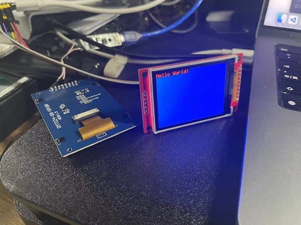
The display is whole and complete and no flower screen appears. But I still faced that there is no text shown. So I asked again that I show give the screen initialization some time. So I added delay(1000) to the code and it looks good:
Design PCB on the KiCAD
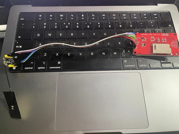
I measured the connectors on the display and it quite fit. But the Grove connector is not well, I might need more resource for that.
Any way, I first check the principle of the display and connect them one by one to the XIAO:
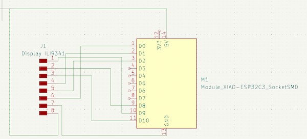
Then I add one Conn_PinHeader_1x04_P2.54mm_Vertical_THT_D1mm as Grove connector represented. But the parameter seems not quite fit(this is later I known).
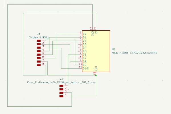
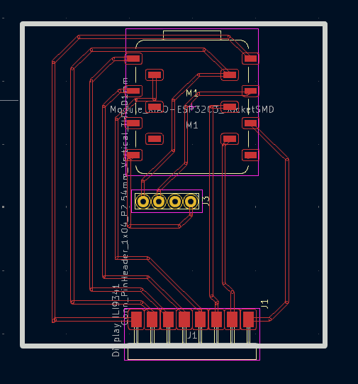
In order to walk the line more easily, to adjust the back and forth. This is final version:
Hence the display code will be:
#define TFT_CS     A0
#define TFT_RST    A2
#define TFT_DC     A1
#define TFT_MOSI   10
#define TFT_CLK    8
TFT_LED connector just connect to a HIGH level Pin 9.
And the signal connecotor of Grove is connecoting D6, or 21.
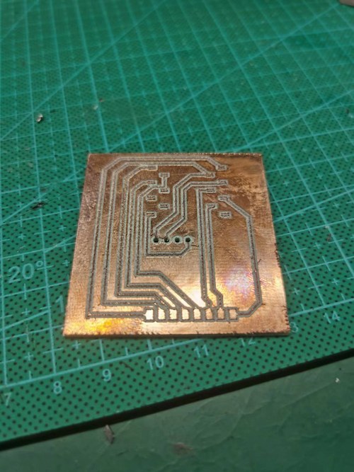
I refer to the previous setting up from week8, and milling:
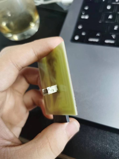
The board is done:
And after soldering:
Front:
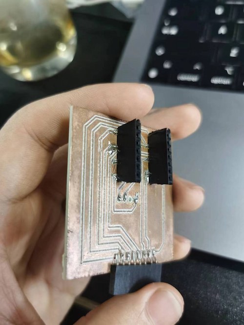
and back:
Connection Check
Read the serial port and display text
Here is the code:
#include <SPI.h>
#include <Adafruit_GFX.h>    // Core graphics library
#include <Adafruit_ILI9341.h> // Hardware-specific library

// 定义使用的引脚
#define TFT_CS     A0
#define TFT_RST    A2
#define TFT_DC     A1
#define TFT_MOSI   10
#define TFT_CLK    8
#define TFT_LED    A3   // 如果不控制背光,可以忽略这个引脚或始终保持为HIGH

// 初始化Adafruit ILI9341
Adafruit_ILI9341 tft = Adafruit_ILI9341(TFT_CS, TFT_DC, TFT_RST);

void setup() {
  Serial.begin(9600); // 初始化串口通信,设置波特率为9600
  pinMode(TFT_LED, OUTPUT);
  digitalWrite(TFT_LED, HIGH); // 开启背光

  tft.begin(); // 初始化屏幕
  delay(1000);
  tft.setRotation(1); // 根据需要设置屏幕方向

  // 清屏
  tft.fillScreen(ILI9341_BLUE);

  // 设置文字颜色和背景颜色
  tft.setTextColor(ILI9341_RED, ILI9341_BLACK);

  // 设置文字大小
  tft.setTextSize(2);

  // 在屏幕上显示 Hello World!
  tft.setCursor(0, 0); // 设置文本开始的位置
  tft.println("Hello World!");
}

void loop() {
  // 检查是否有串口数据可读
  if (Serial.available()) {
    // 读取串口数据
    String input = Serial.readStringUntil('\n');

    // 在屏幕上显示读取到的数据
    tft.println(input);
  }
}
Turn on Relay
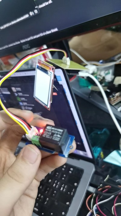
Here is the code
// Relay Control

void setup()
{
  pinMode(D6, OUTPUT);
}

void loop()
{

    digitalWrite(D6, HIGH);

}
Begin Development
For my final, I want to ensure that the board can read outside text/image information and display them. Thus I am going to develop base on them.
Drawing Static Image
From the same wiki TFT touch shield wiki, I have learnt that there are multiple functions to draw an image:
Lines:
drawLine(unsigned int x0,unsigned int y0,unsigned int x1,unsigned int y1,unsigned int color) - Draws a line from pixel (x0,y0) to pixel (x1,y1) with color color.drawVerticalLine(unsigned int poX, unsigned int poY,unsigned int length,unsigned int color) - Draws a Horizontal Line of length length with color color starting from pixel (poX,poY).drawHorizontalLine(unsigned int poX, unsigned int poY,unsigned int length,unsigned int color) - Draws a Vertical Line of length length with color color starting from pixel (poX,poY).
Rectangle:
drawRectangle(unsigned int poX, unsigned int poY, unsigned int length,unsigned int width,unsigned int color) - Draws a rectangle starting from (poX,poY) of length length, width width and color color.fillRectangle(unsigned int poX, unsigned int poY, unsigned int length, unsigned int width, unsigned int color) - Draws a filled rectangle starting from pixel (poX,poY) of length length, width width and color color.
Circle
drawCircle(int poX, int poY, int r,unsigned int color) - Draws a circle at (poX,poY) of radius radius and color color.fillCircle(int poX, int poY, int r,unsigned int color) - Draws a filled circle at (poX,poY) of radius radius and color color.
Thus, I am using fillRect, fillCircle, fillTriangle, fillCircle to draw a dog, with GPT help of course:
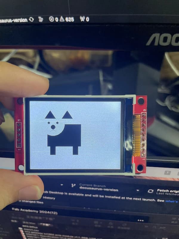
And this is the code:
#include <SPI.h>
#include <Adafruit_GFX.h>
#include <Adafruit_ILI9341.h>

#define TFT_CS     A0
#define TFT_RST    A2
#define TFT_DC     A1
#define TFT_MOSI   10
#define TFT_CLK    8
#define TFT_LED    A3

Adafruit_ILI9341 tft = Adafruit_ILI9341(TFT_CS, TFT_DC, TFT_RST);

void setup() {
  pinMode(TFT_LED, OUTPUT);
  digitalWrite(TFT_LED, HIGH);

  tft.begin();
  delay(1000);
  tft.setRotation(1);

  tft.fillScreen(ILI9341_WHITE);

  drawDog();
}

void loop() {

}

void drawDog() {
  // 绘制小狗的身体
  tft.fillRect(60, 80, 120, 80, ILI9341_BLACK);
  tft.fillRect(80, 120, 80, 40, ILI9341_BLACK);
  // 绘制小狗的头部
  tft.fillCircle(80, 80, 40, ILI9341_WHITE);
  // 绘制小狗的耳朵
  tft.fillTriangle(50, 60, 70, 30, 90, 60, ILI9341_BLACK);
  tft.fillTriangle(110, 60, 130, 30, 150, 60, ILI9341_BLACK);

  // 绘制小狗的眼睛
  tft.fillCircle(65, 75, 8, ILI9341_WHITE);
  tft.fillCircle(95, 75, 8, ILI9341_WHITE);
  tft.fillCircle(65, 75, 4, ILI9341_BLACK);
  tft.fillCircle(95, 75, 4, ILI9341_BLACK);

  // 绘制小狗的鼻子
  tft.fillCircle(80, 90, 8, ILI9341_BLACK);

  // 绘制小狗的嘴巴
  tft.drawLine(80, 90, 80, 100, ILI9341_BLACK);
  tft.drawLine(80, 100, 70, 105, ILI9341_BLACK);
  tft.drawLine(80, 100, 90, 105, ILI9341_BLACK);

  // 绘制小狗的腿
  tft.fillRect(70, 160, 20, 30, ILI9341_BLACK);
  tft.fillRect(150, 160, 20, 30, ILI9341_BLACK);
}
Processing Static Image
This takes me quite a time, and it also proved that the MAC was not well suited for MCU development...
- After developing with MicroPython, the board will display unknow port and change the connection every time uploading. - Need to select the right port everytime
- The libraries are easily misled, especially if there are similar libraries and the same variable declarations.- Need to delete the misled one.
There are two ways to I found that can implement the image processing on the board:
- Convert the image(PNG, JPG) into ".bmp" file(Bitmap format) then into HEX code.
- Convert the image(PNG, JPG) into ".bin" file.
HEX code generation and usage
I love a game called "Genshin" and a character called "HuTao". I want to use this character as my example file.
I first use GTMP software to convert it into a ".bmp" file, and output the format with my display:
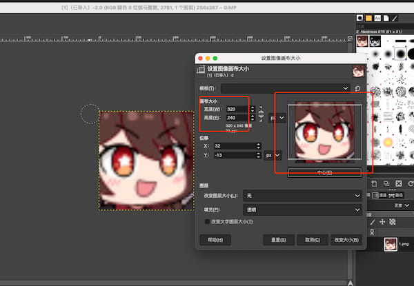
Then I went to the LVGL Converter to change this file into required C arrey. But in the C arrey, there are multiple types as well, and I just need to selece my type(RGB565 16 BIT).
Finally I use this code(powered by GPT):
#include <SPI.h>
#include <Adafruit_GFX.h>
#include <Adafruit_ILI9341.h>

#define TFT_CS     A0
#define TFT_RST    A2
#define TFT_DC     A1
#define TFT_MOSI   10
#define TFT_CLK    8
#define TFT_LED    A3

Adafruit_ILI9341 tft = Adafruit_ILI9341(TFT_CS, TFT_DC, TFT_RST);

#define _1_HEIGHT 240
#define _1_WIDTH 320

static const uint16_t _1[] PROGMEM = {

// this is where I put the HEX code

};

void setup() {
  pinMode(TFT_LED, OUTPUT);
  digitalWrite(TFT_LED, HIGH);

  tft.begin();
  delay(1000);
  tft.setRotation(1);

  tft.fillScreen(ILI9341_BLACK);

  drawImage();
}

void loop() {
  // 不需要重复执行任何代码
}

void drawImage() {
  tft.drawRGBBitmap(0, 0, _1, _1_WIDTH, _1_HEIGHT);
}
to implement my display:
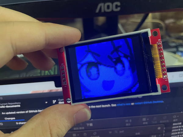
There are still many problems that need to be solved, like the RGB display, it will automatically disappear after 1 minute, etc.
".bin" file generation and usageFor the first one**
This is still under development.
Because my final goal is acvieving the GIF display, and the HEX code is taking too much spaces, batch management of images is necessary.
So I found out I can display the image directly using the ".bin" file that contains the image data.
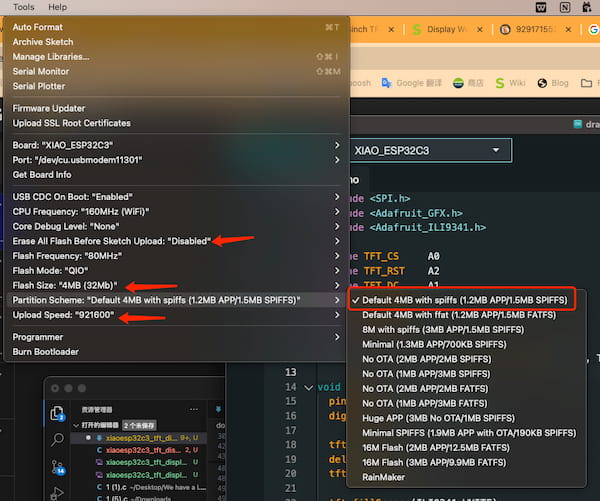
It requires the MCU board containing the SPIFFS function(Onboard file system) and luckly the XIAO ESP32C3 is supporting it and just be careful for the Flash Size and other Flash function choosing:
I convert my images into serval ".bin" files with "
Then create a folder called "data" under the same path of the code folder:
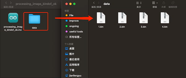
After uploading the code, the Arduino IDE will automatically upload the "data" files in the data directory to the onboard file system.
Finally I can call them, using this custom function drawImageFromBin:
void drawImageFromBin(const char* filename, int16_t x, int16_t y) {
  File file = SPIFFS.open(filename, "r");
  if(!file){
    Serial.println("Failed to open file for reading");
    return;
  }

  uint16_t* data = (uint16_t*)malloc(file.size());
  if (!data) {
    Serial.println("Failed to allocate memory");
    file.close();
    return;
  }

  file.read((uint8_t*)data, file.size());
  file.close();

  // 根据你的图片格式和显示屏库调用相应的绘制函数
  // 例如,对于 RGB565 格式和 Adafruit_ILI9341 库:
  tft.drawRGBBitmap(x, y, data, _1_WIDTH, _1_HEIGHT);

  free(data);
}
in the loop:
void loop() {

  drawImageFromBin("/1.bin", 0, 0);
  drawImageFromBin("/2.bin", 0, 0);
  drawImageFromBin("/3.bin", 0, 0);
  drawImageFromBin("/4.bin", 0, 0);

}
But I have this error(no finding):
22:28:11.033 -> File does not exist
22:28:11.102 -> Failed to allocate memory
I am stilling finding the solution.