4. Computer-controlled cutting
This week is to use lazer cut machine and vinyl cut machine.
Group Work
Lazer cutting
We used lazer cut machine from rayjetlaser. The model is r400.
The documentation is here.
Something what I learned: 1. The most important when using lazer cutting machine is SAFETY. One should never leave when doing cutting, and anyone should stop the machine immdiately when find the machine is under nobody’s surveillance.
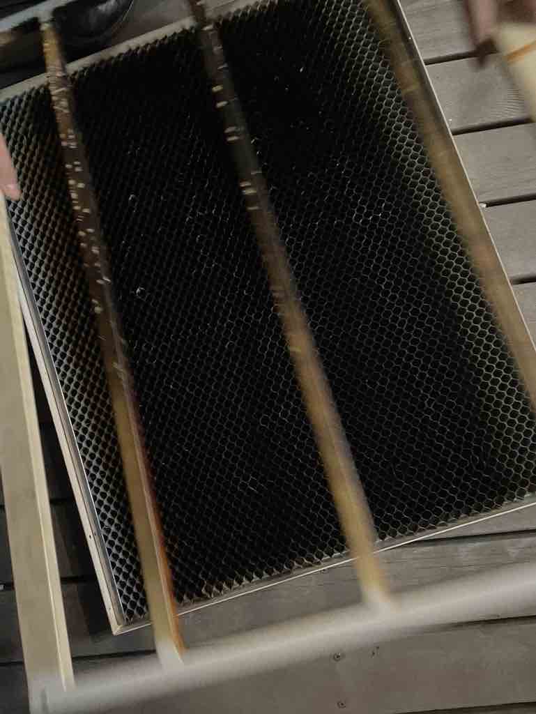
- Maintenance of the machine: It’s necessary to do the maintenance work for our lasercutter after using it. Clean the focus lens and the reflecing mirror, clean the waste bin…
Without clean for a long time it will become like the image bellow.
- Material Setup: Position the material to be cut on the machine’s cutting bed or platform securely. Use clamps or magnets if necessary to prevent movement during the cutting process. Ensure that the material is flat and free from any obstructions that may interfere with the laser beam.
And make sure the material is not poison when cutting.
-
Machine Setup: Set the appropriate cutting parameters such as laser power, cutting speed, and focal length based on the material being cut. These settings may vary depending on the material’s thickness and type.
-
Test Run: Before cutting the actual design, it’s advisable to perform a test run on a scrap piece of the same material to verify the cutting parameters and ensure the desired results are achieved.
Do cutting without test always results in not good situation.
Vinyl cutting
Group work
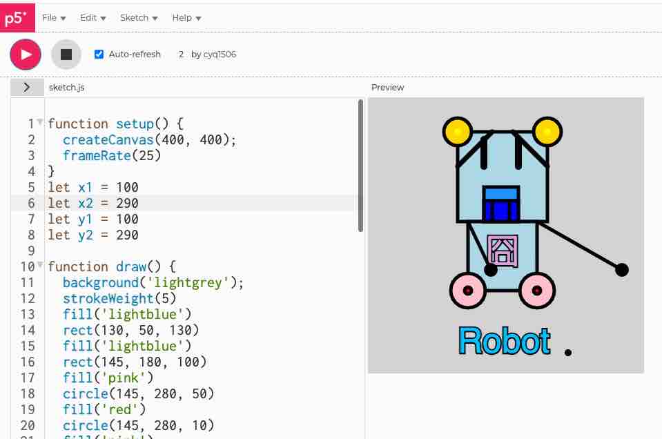
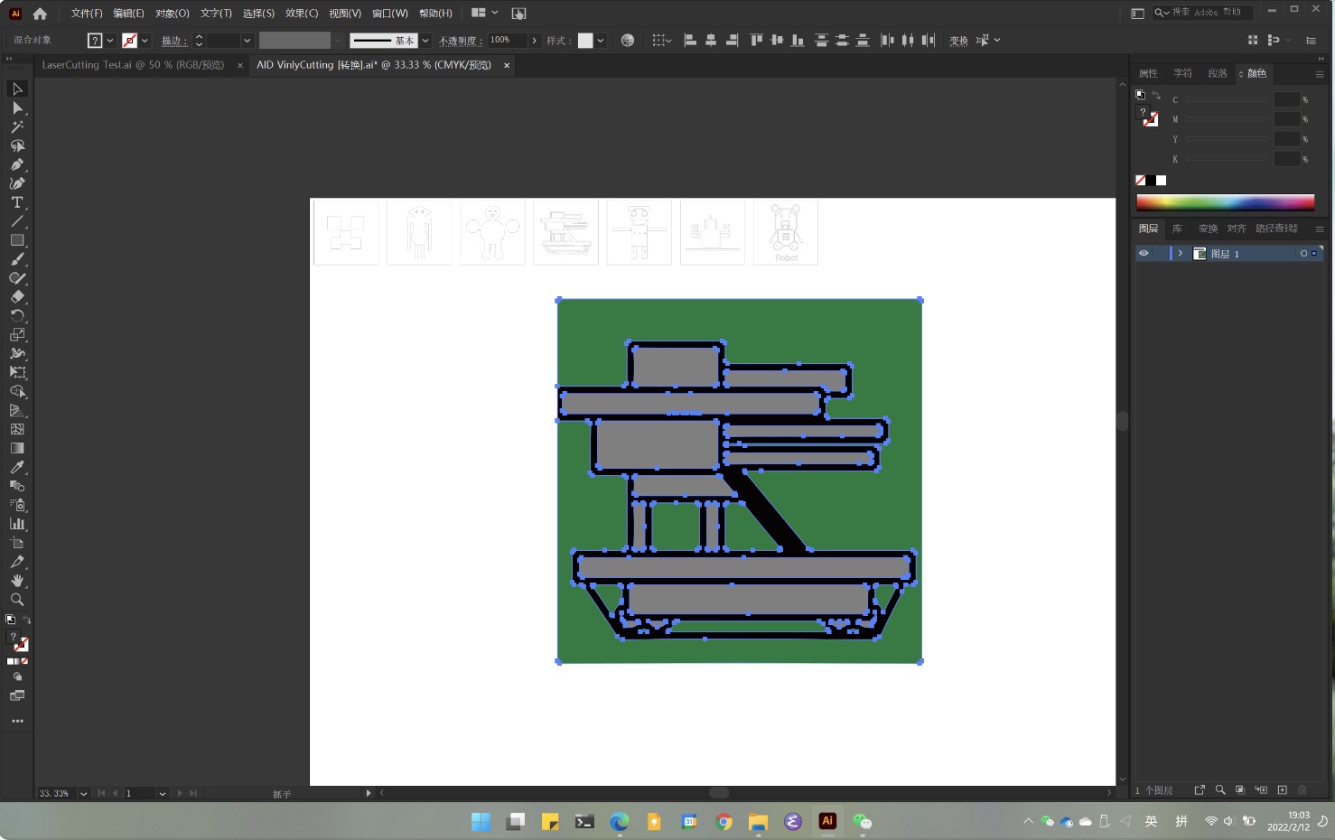
In this week we are having a class with teenageers. We teach them to code in P5js. They draw some robots in class with basic graphs in p5js. So we decided to cut the robots with vinyl macheine.
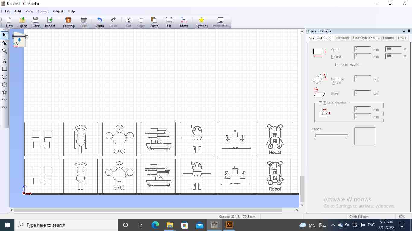
After you load the material, you have to select if it is a ROLL or a SHEET. Select the force value. This will depend on the material sheet grammage. The position where you locate the vectors will affect where the machine will cut, so the preview you see on the artboard of the software is actually the place where the machine will cut it.
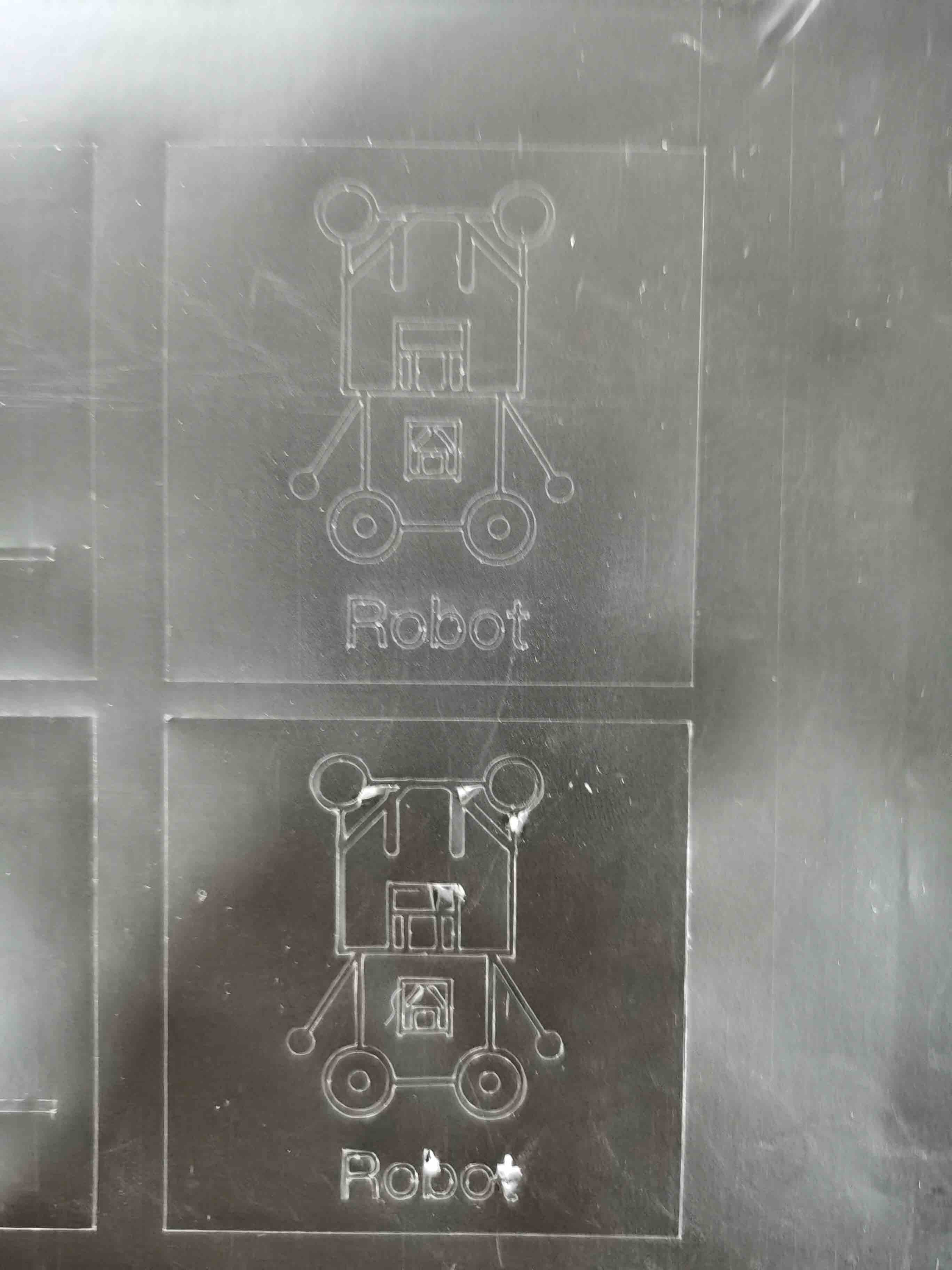
This one was coded by a 13 years old girl called Raiching.
This piece was created by a 9 years old boy.
We used this materal and it was jammed, because the material is too long, so we cut a small piece and put it into the machine.
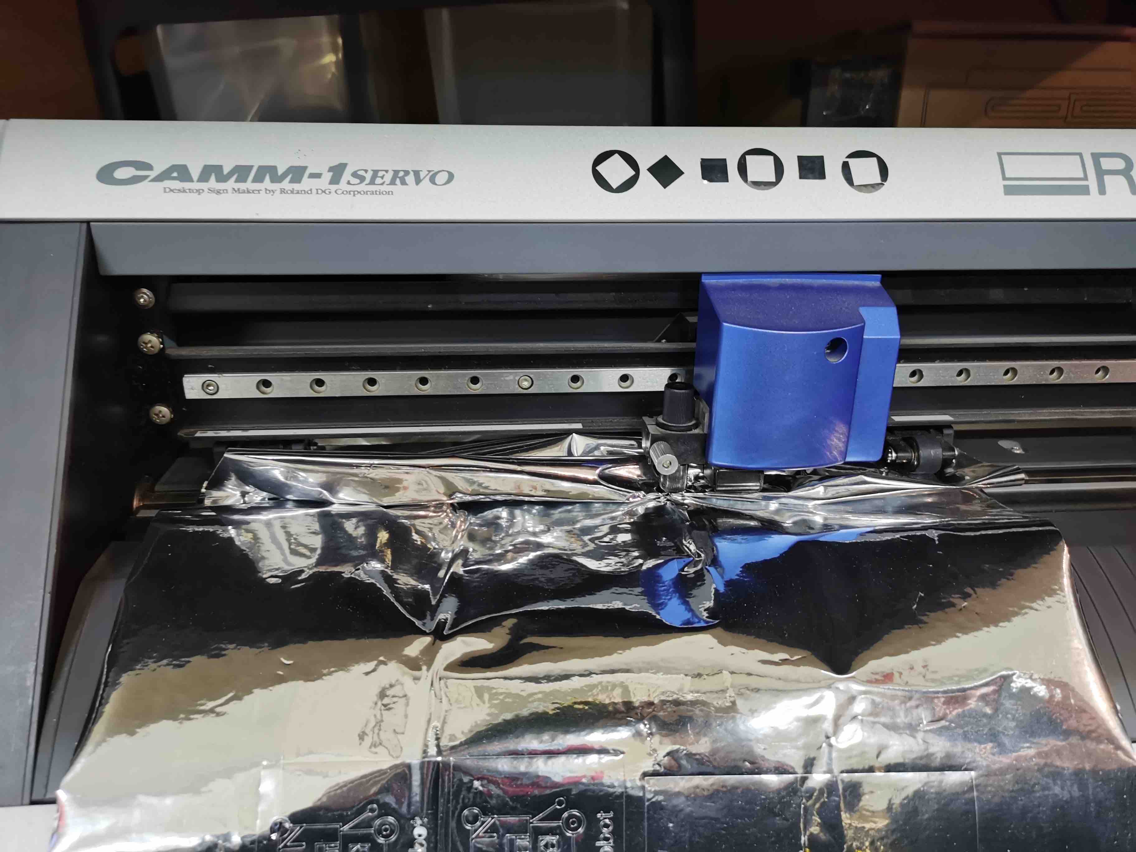
Change the force a little when it is cutting. The upper bear is adusted to lower, so the result comes better.
Ready to give it to students:
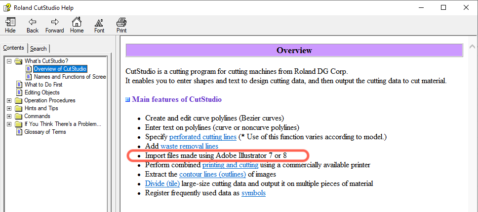
One thing to mention is that CutStudio only accept ai file of Illustrator 7 or 8.
My work
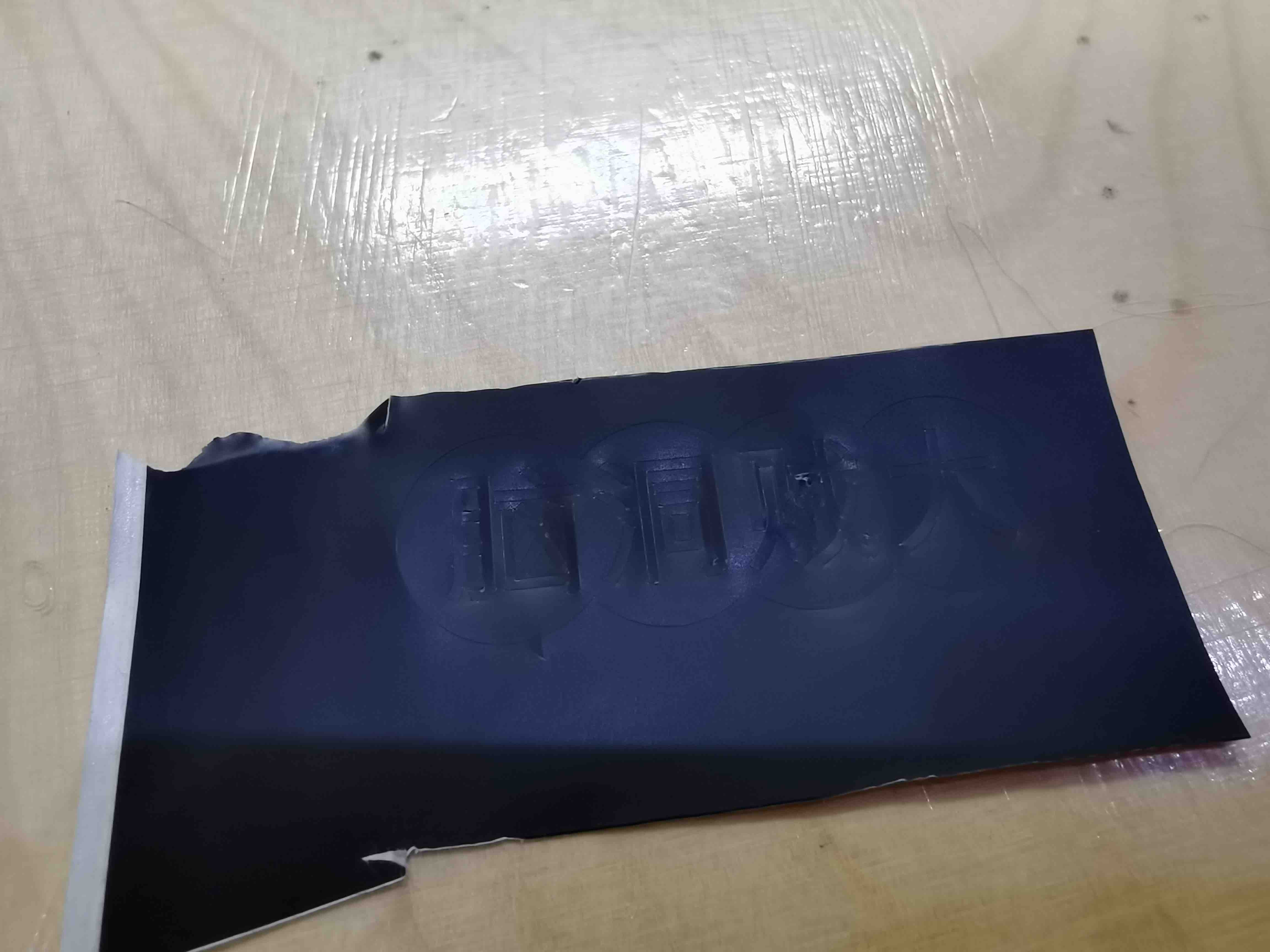
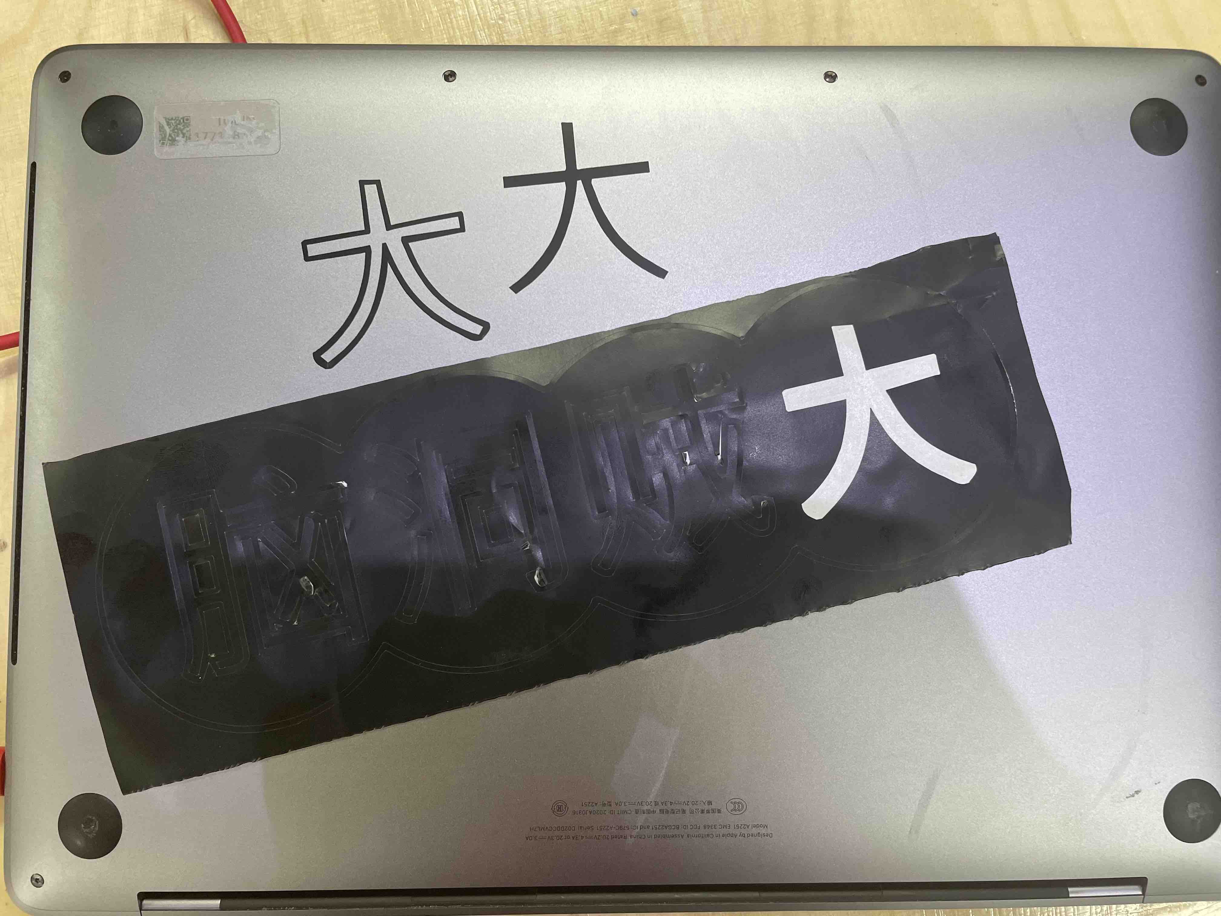
I want to make a sticker for the “Design Thinking” workshop. The Chinese words of “脑洞贼大” means you have a big brain hole which also means you can think out of the mind without limitations.
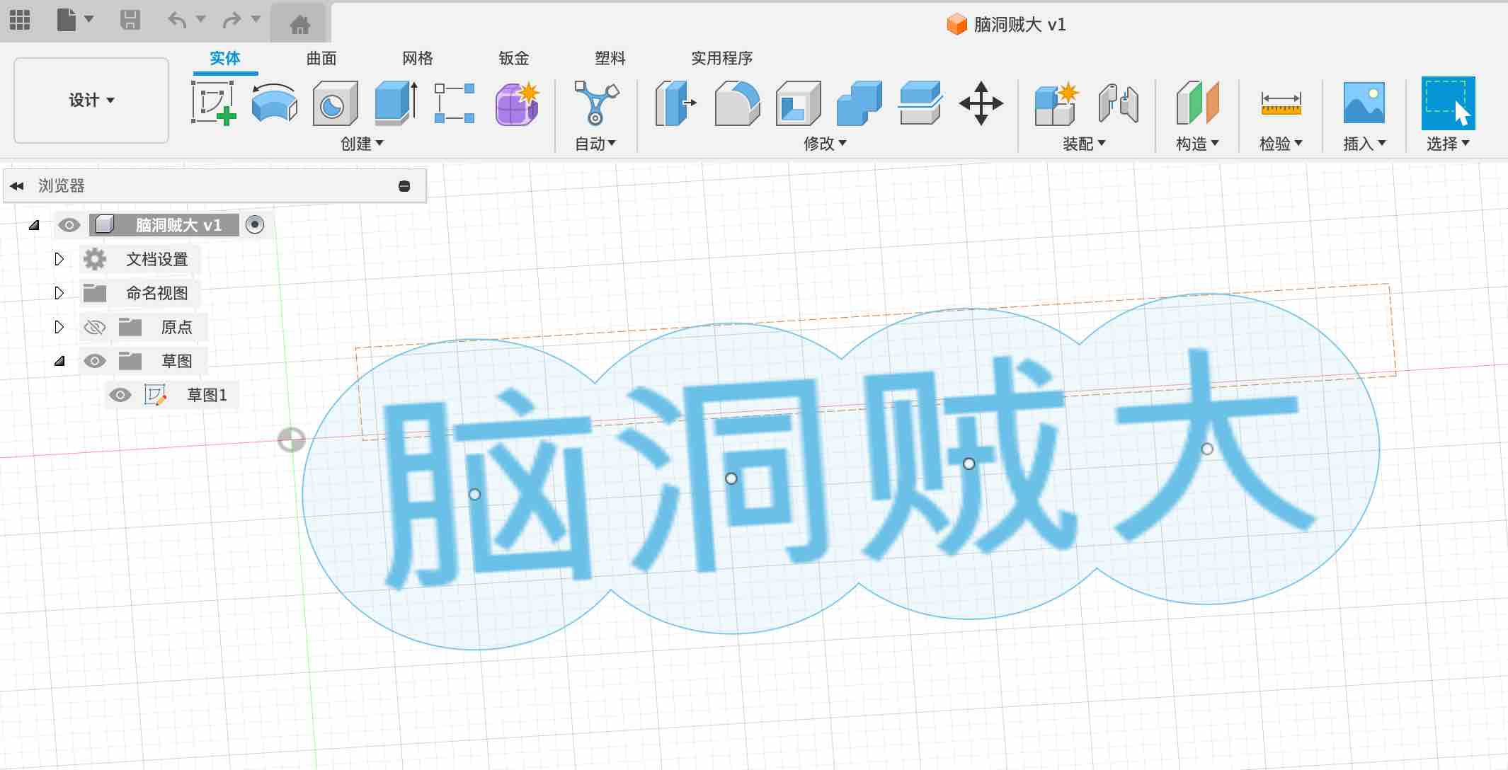
Start to cut:
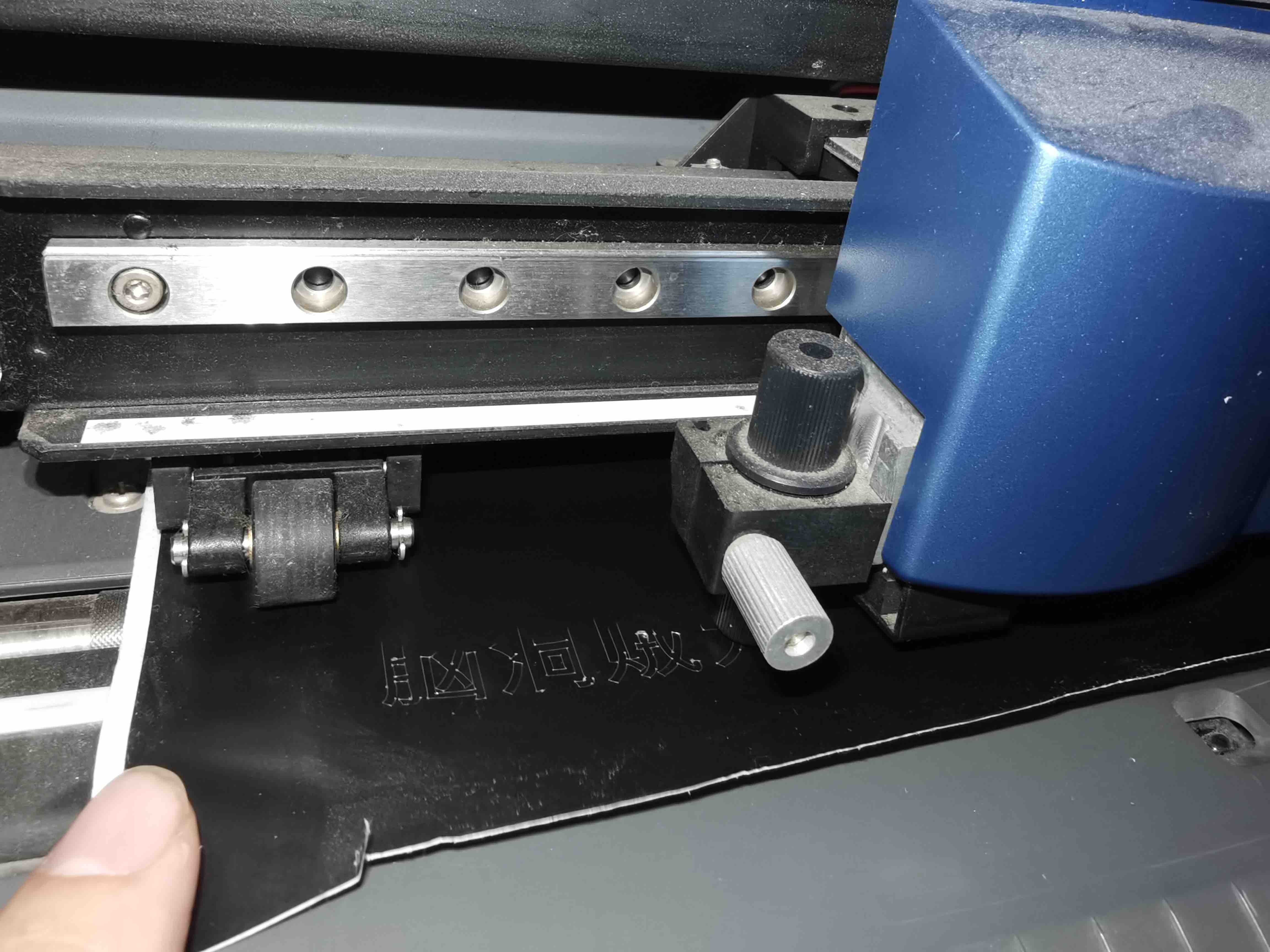
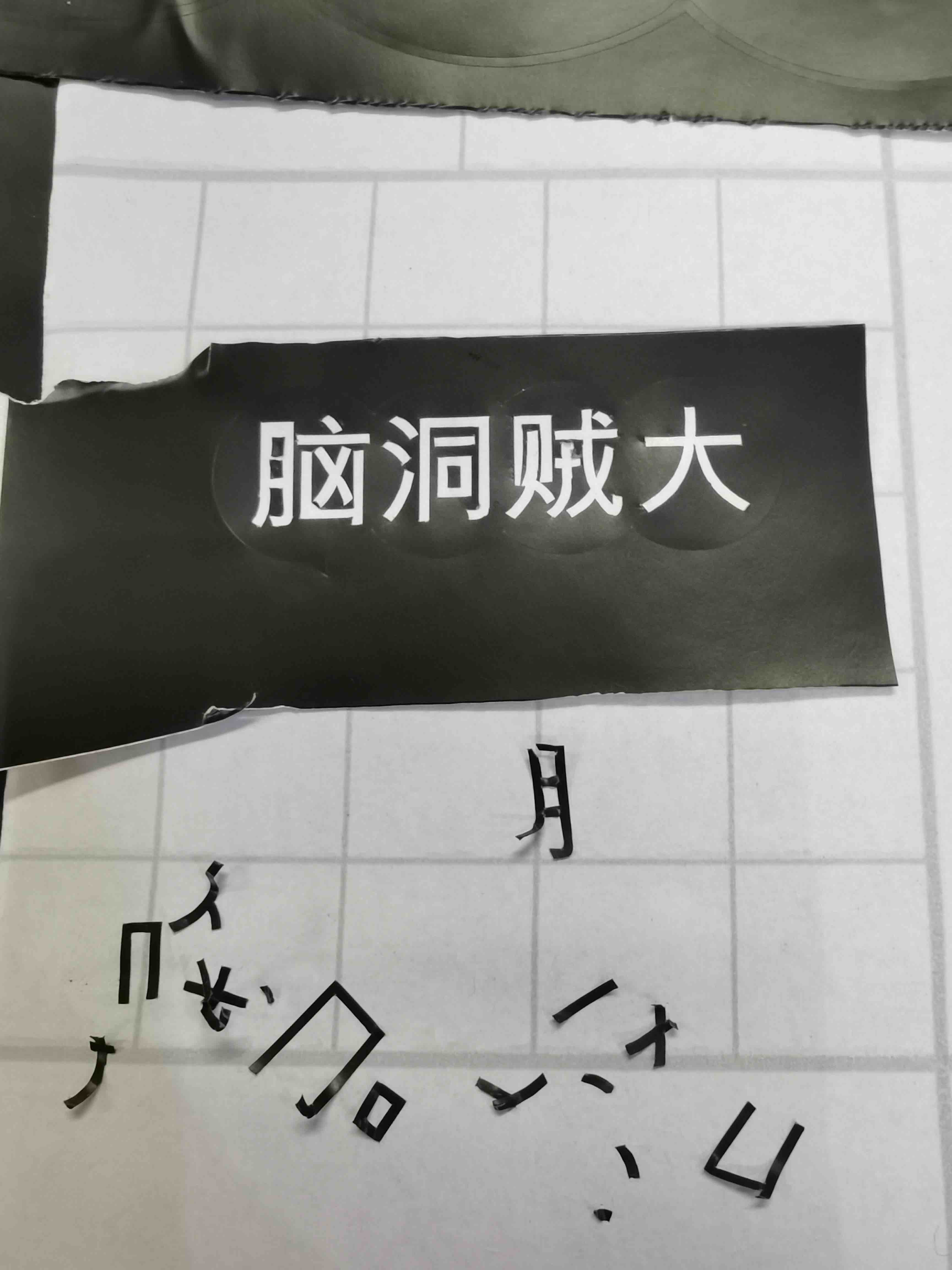
So far so good:
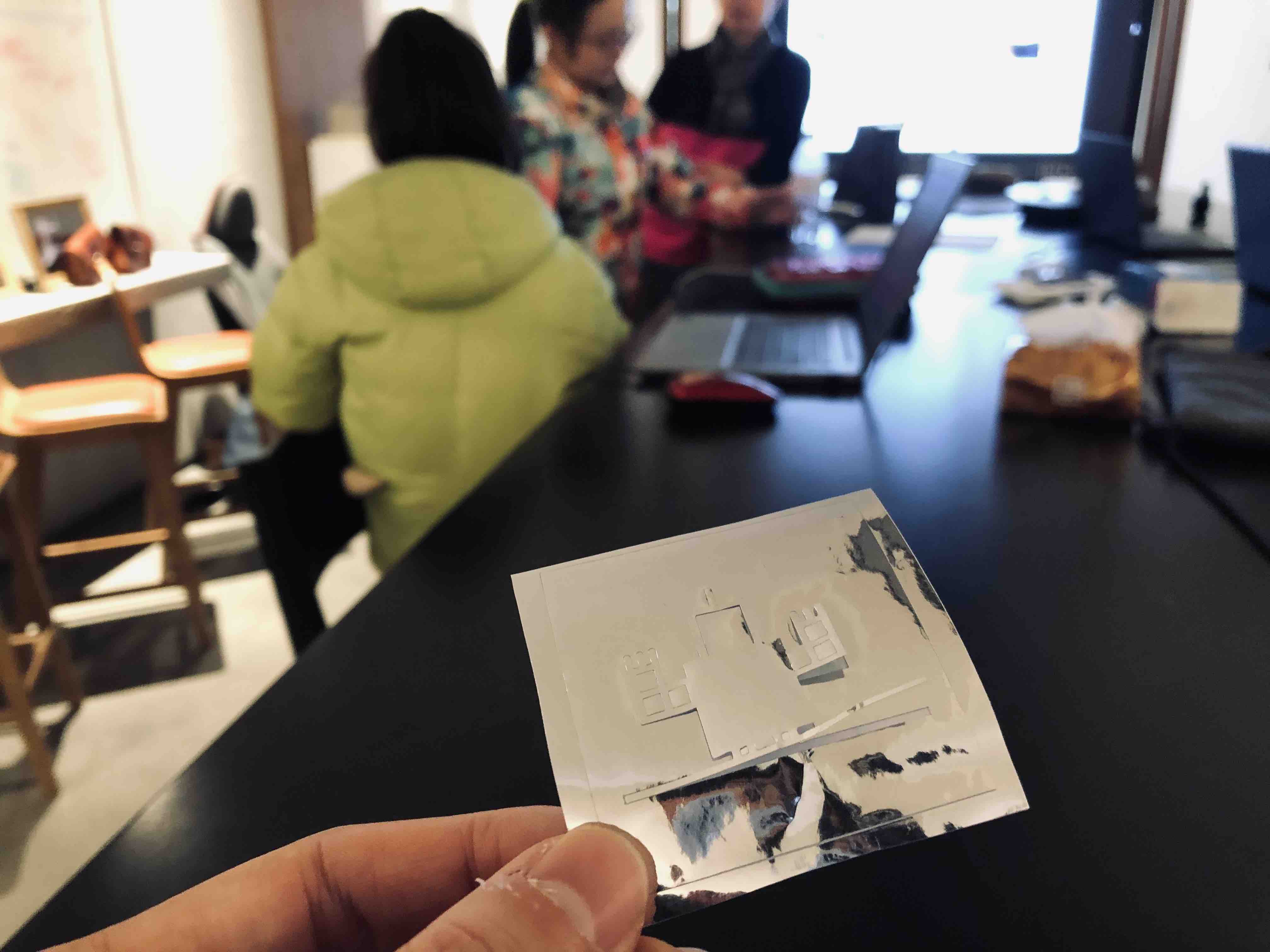
It takes me like almost 20 minutes to remove the small parts and without damage the remaining part!
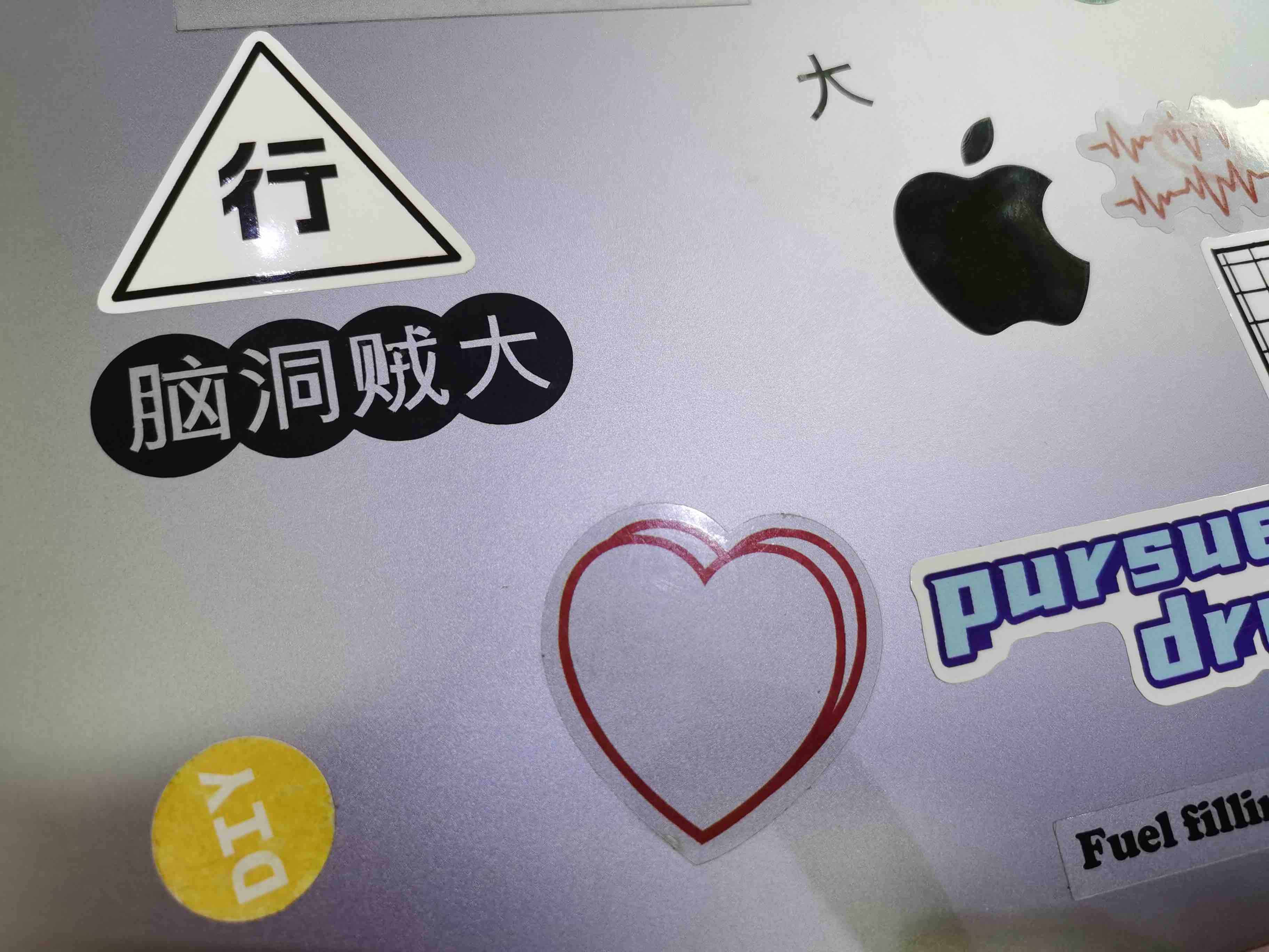
Here it goes:
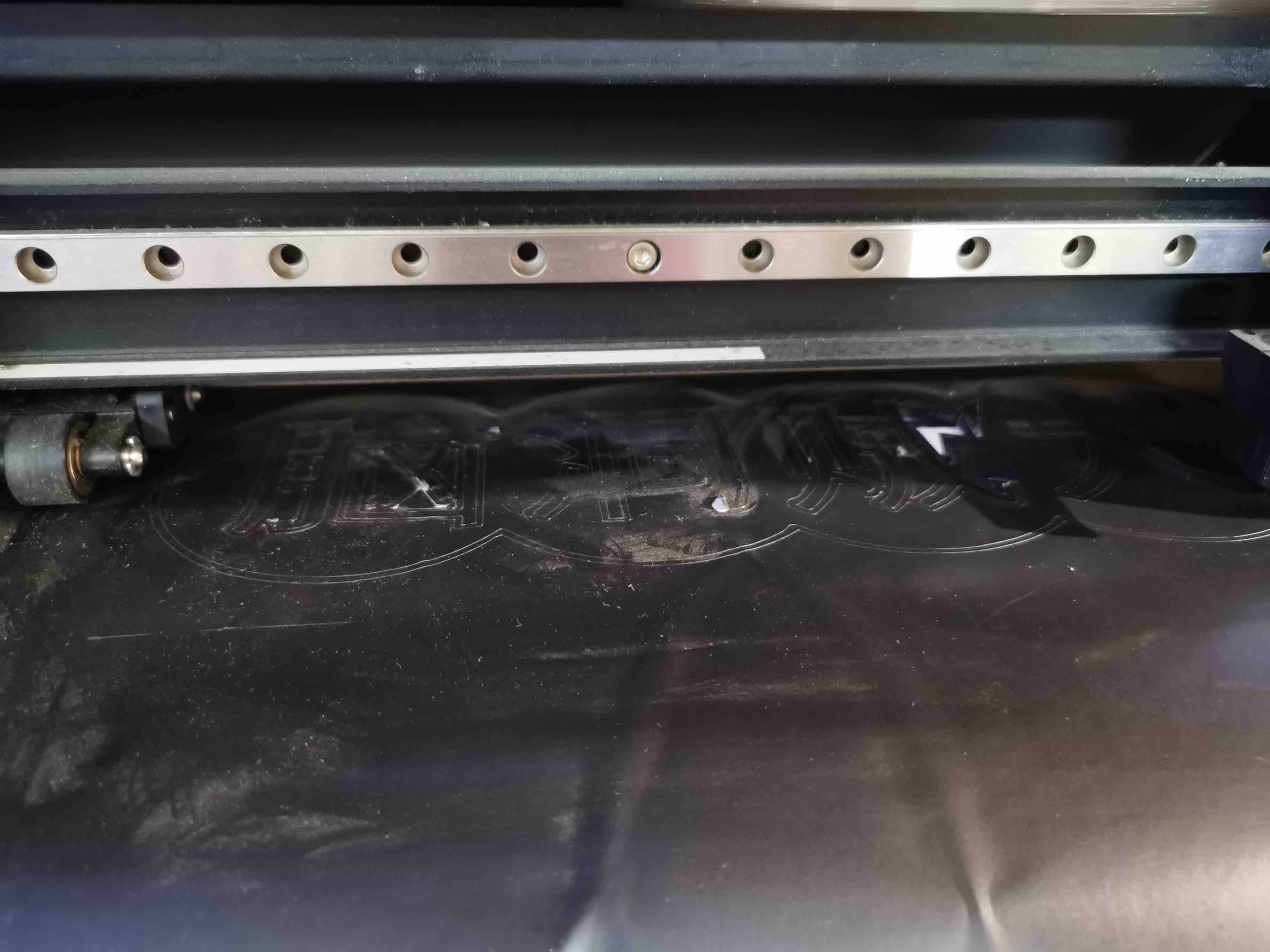
Another thing to mention is that I tried to import the source file as a PNG to CutStudio, and use the Outline function, it turns out like this. You can see it cuts the line with two strings, in and out, which :
Individual Work
Design Part
I used Fusion360 to do the model design.
Fusion 360 is a cloud-based 3D computer-aided design (CAD), computer-aided engineering (CAE), and computer-aided manufacturing (CAM) software developed by Autodesk. It is a powerful and comprehensive tool that combines design, simulation, and manufacturing capabilities into a single platform.
Generative Design: Fusion 360 includes generative design capabilities that use algorithms to generate optimized designs based on specified constraints and goals.
I am a new bee to 3D design. Compare with Rhino, I would definately choose Fusion 360 to do modeling. It is much easer to use and friendly to beginer. And the paramtric design is very amazing which links to my coding knolwedge.
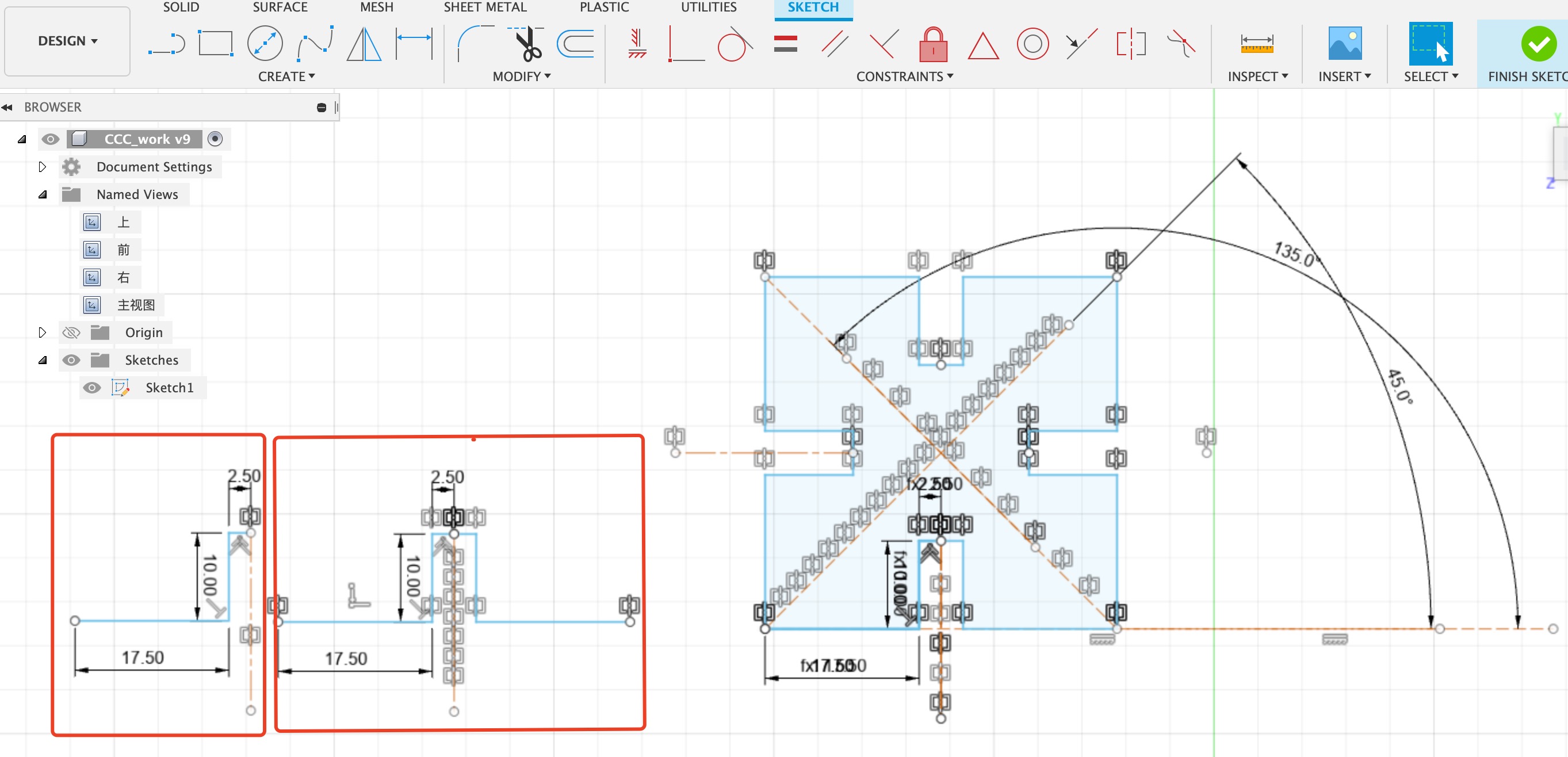
- Because we are using params to make the model. So create parameters first:
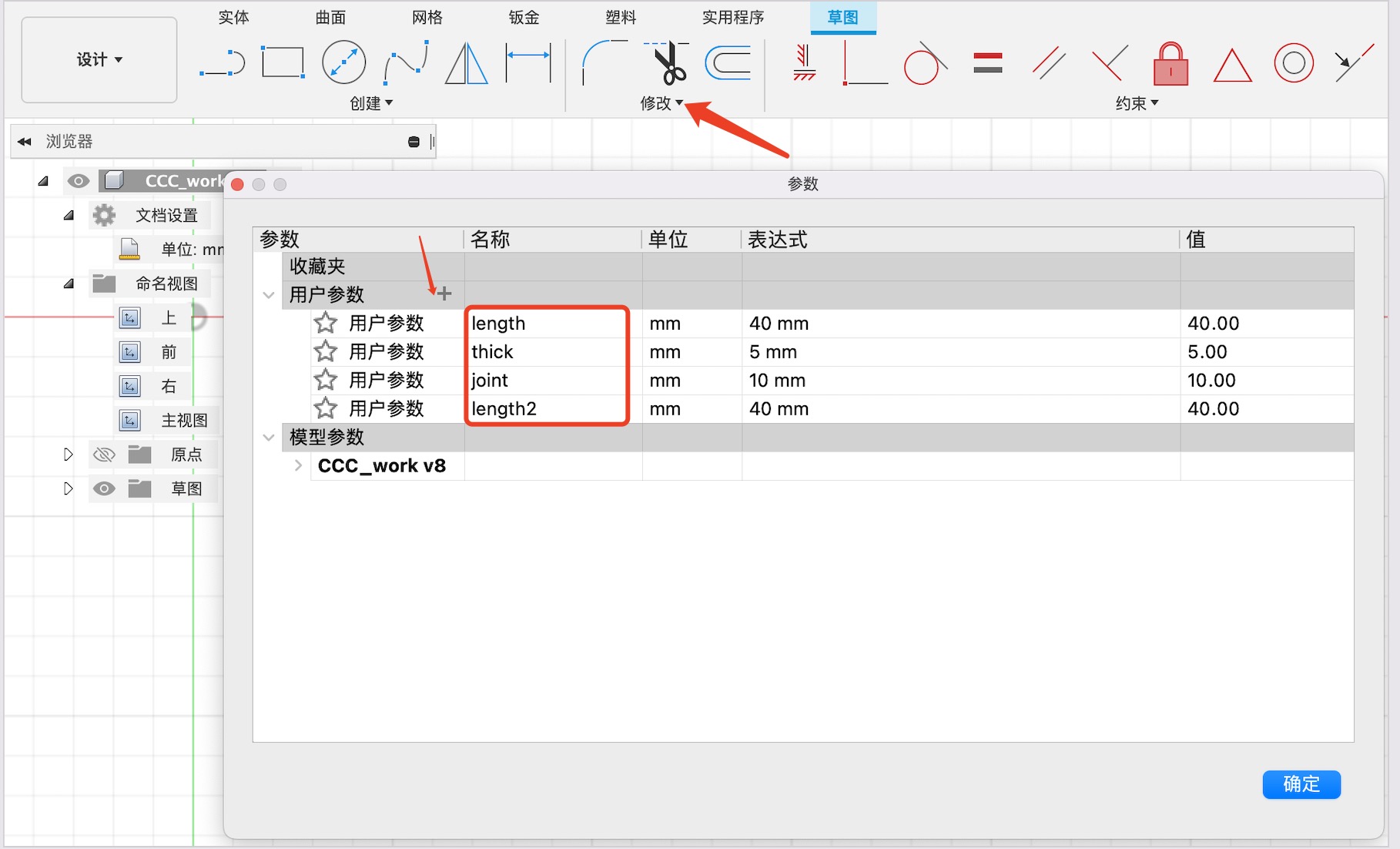
I created for parameters according to the joints size.
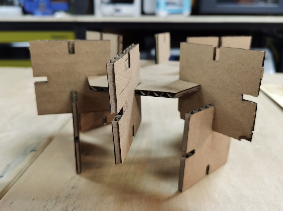
- Model design
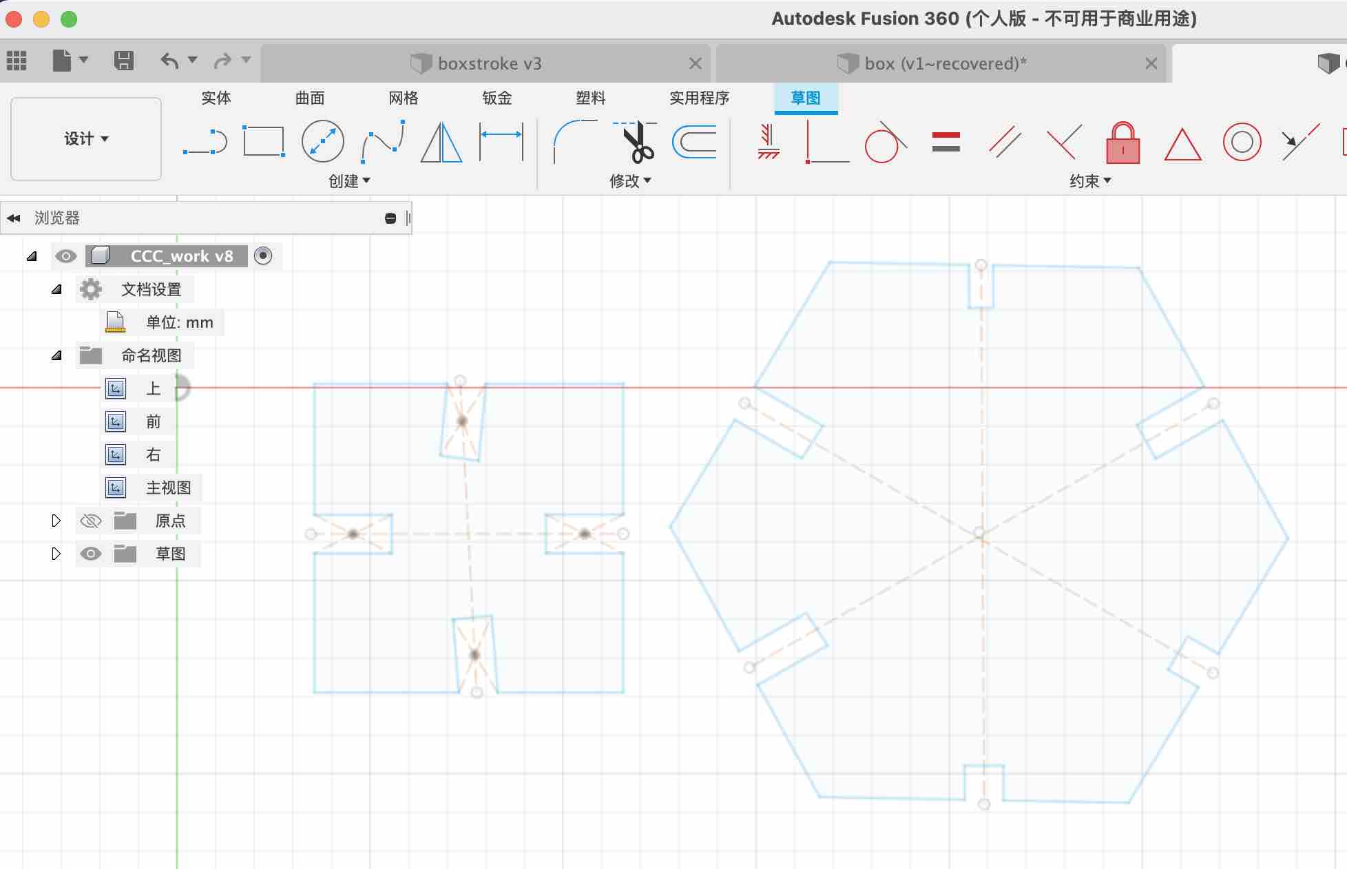
Here I tried to use triangle first and attach four joint to it. I used constrants of symmetry to make the joints fits in the middle of triangle border.
Frist it seems fine, but when I change the param values it misformed.
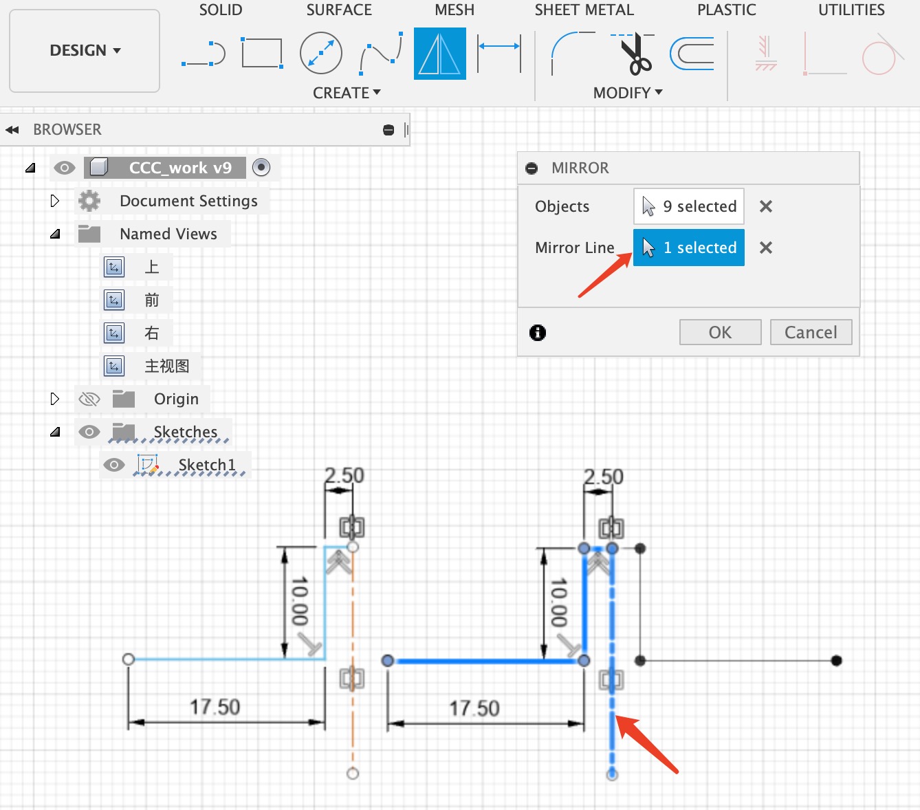
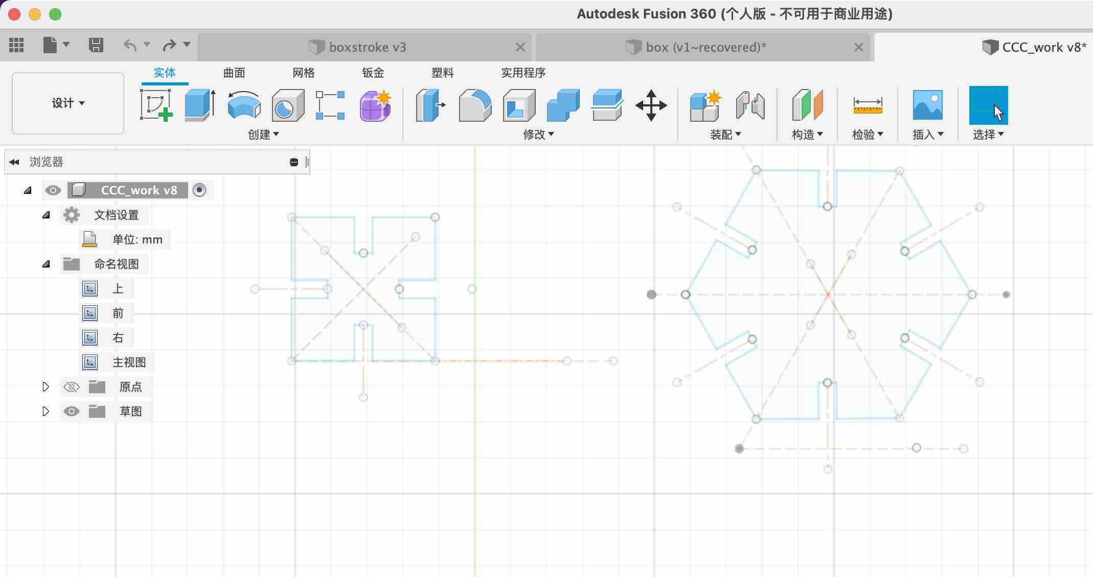
With the help of Saverio, I change to use the Create-Mirror function to make a line first.
 Draw more construction lines and repeat the mirror to make it an tringle.
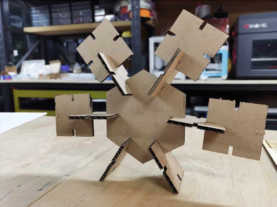
Then control the construction line and make a new hexagon.
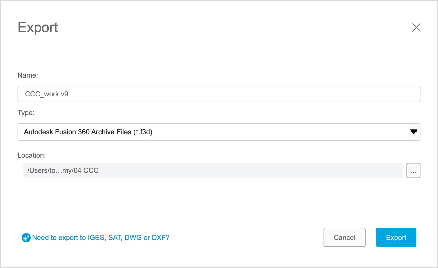
Click on finish and export it to dxf file.
Update in rhino and AI
I tried to open the dxf file in AI, but it couldn’t. So I used rhino and import the fie.
Remove all the lines that I don’t need. Make a repeat of trignale.
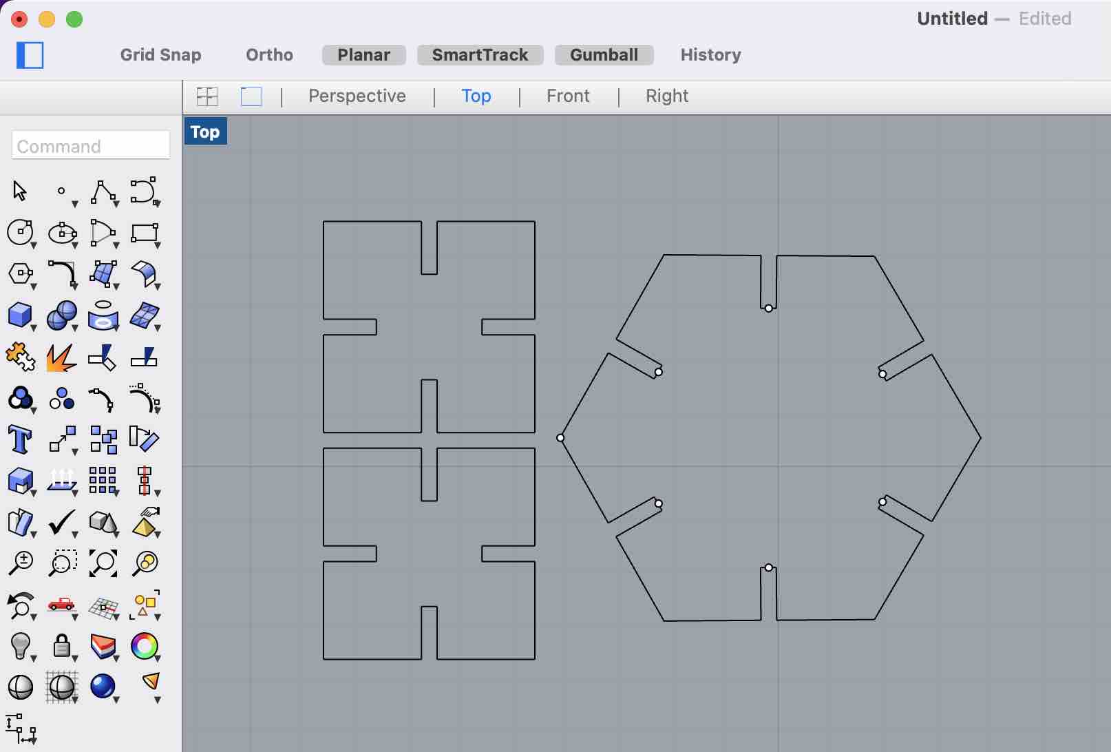 Export it into AI file.
Cut
Important: All the cut lines should be 0.01pt and the color should be color red in RGB mode. I forgot to change the line witdh, and It did not cut.
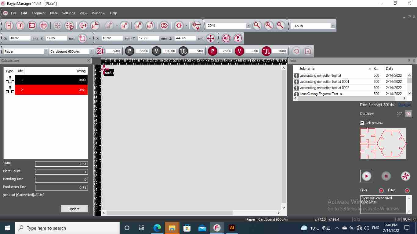
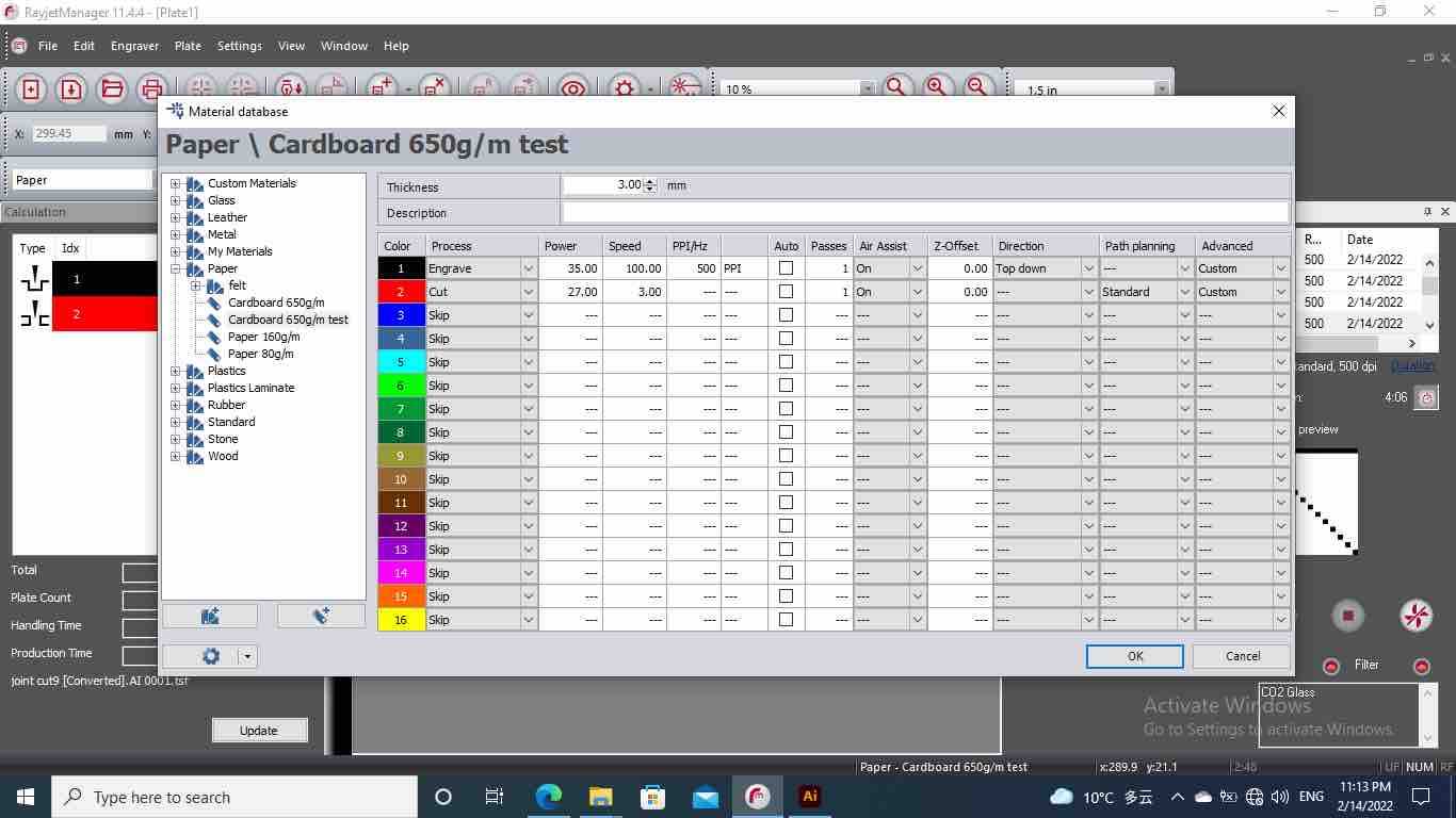
I did test for cutting small pieces first. The first set get a little burned with power 28. The second set is using power 27.

From the test I learned that the cardboad is very easy to get on fire because of it has two layers, and after the lazer go through the first layer, all the heat will stay in-bewteen the two layers and fire will start in the middle. Sometimes the fire can not be observed at the beginning. For now it just got burned because the power is too high.
Here is the MOST INTERESTING part. It got fire when cutting!
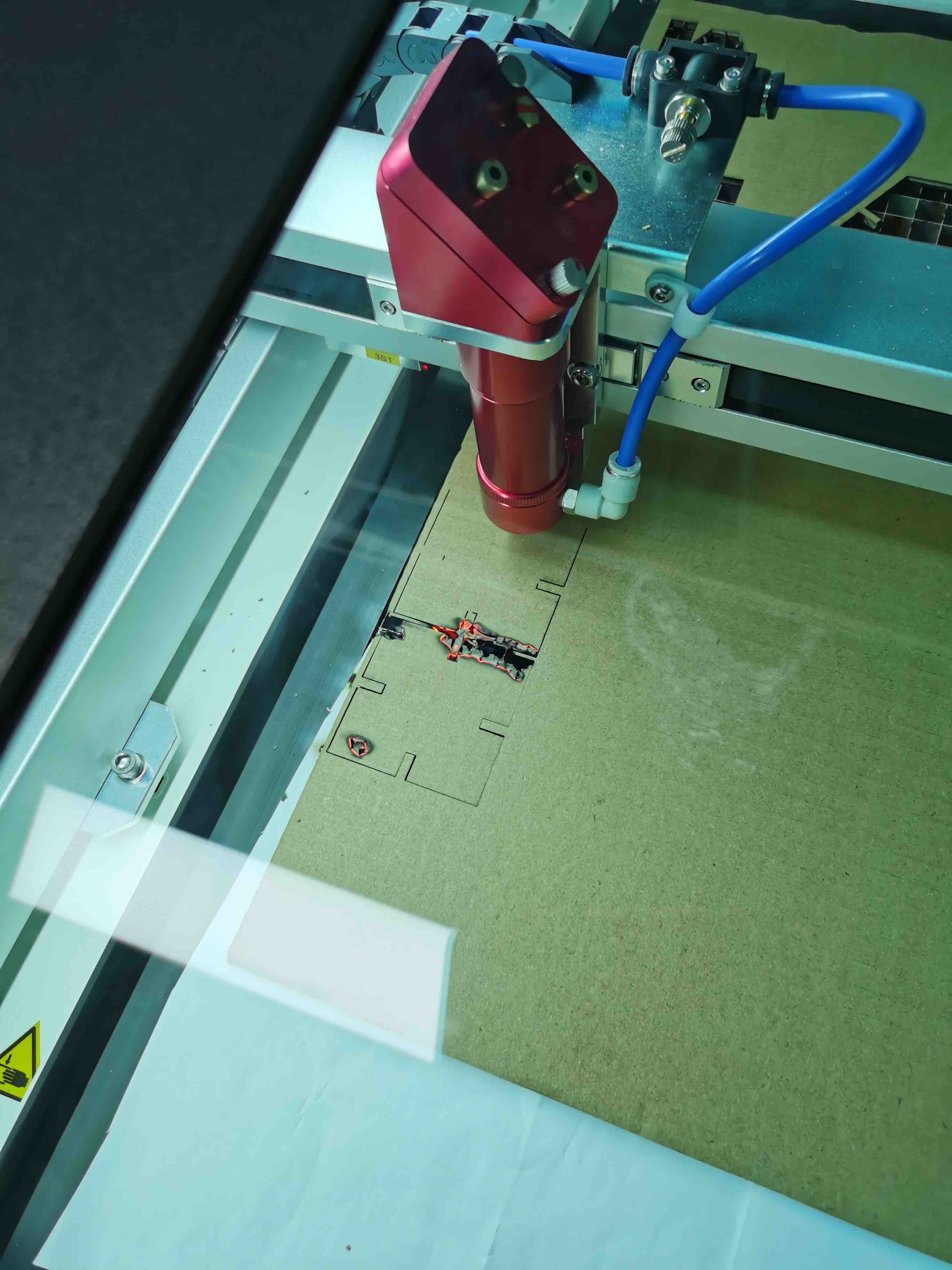 The fire is from the white paper underneath the cardboard. The paper was put there to make the air go down quickly. But it was not supposed to be under the board.
After removing the paper underneath, the cutting go through all good. So the best power is 27.
Combine joints together