13. Input device
Todo list
Group assignment:
- Probe an input device(s)’s analog and digital signals
- Document your work to the group work page and reflect on your individual page what you learned
Individual assignment:
- Measure something: add a sensor to a microcontroller board that you have designed and read it.
Answer these questions:
- Linked to the group assignment page
- Documented what you learned from interfacing an input device(s) to microcontroller and how the physical property relates to the measured results
- Documented your design and fabrication process or linked to previous examples.
- Explained the programming process/es you used
- Explained problems and how you fixed them
- Included original design files and source code
- Included a ‘hero shot/video’ of your board
Light sensor
See there are a lot of different kinds of light sensors.
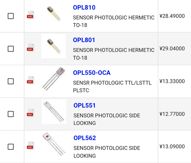
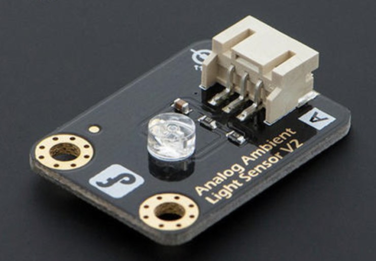
What I have right now:
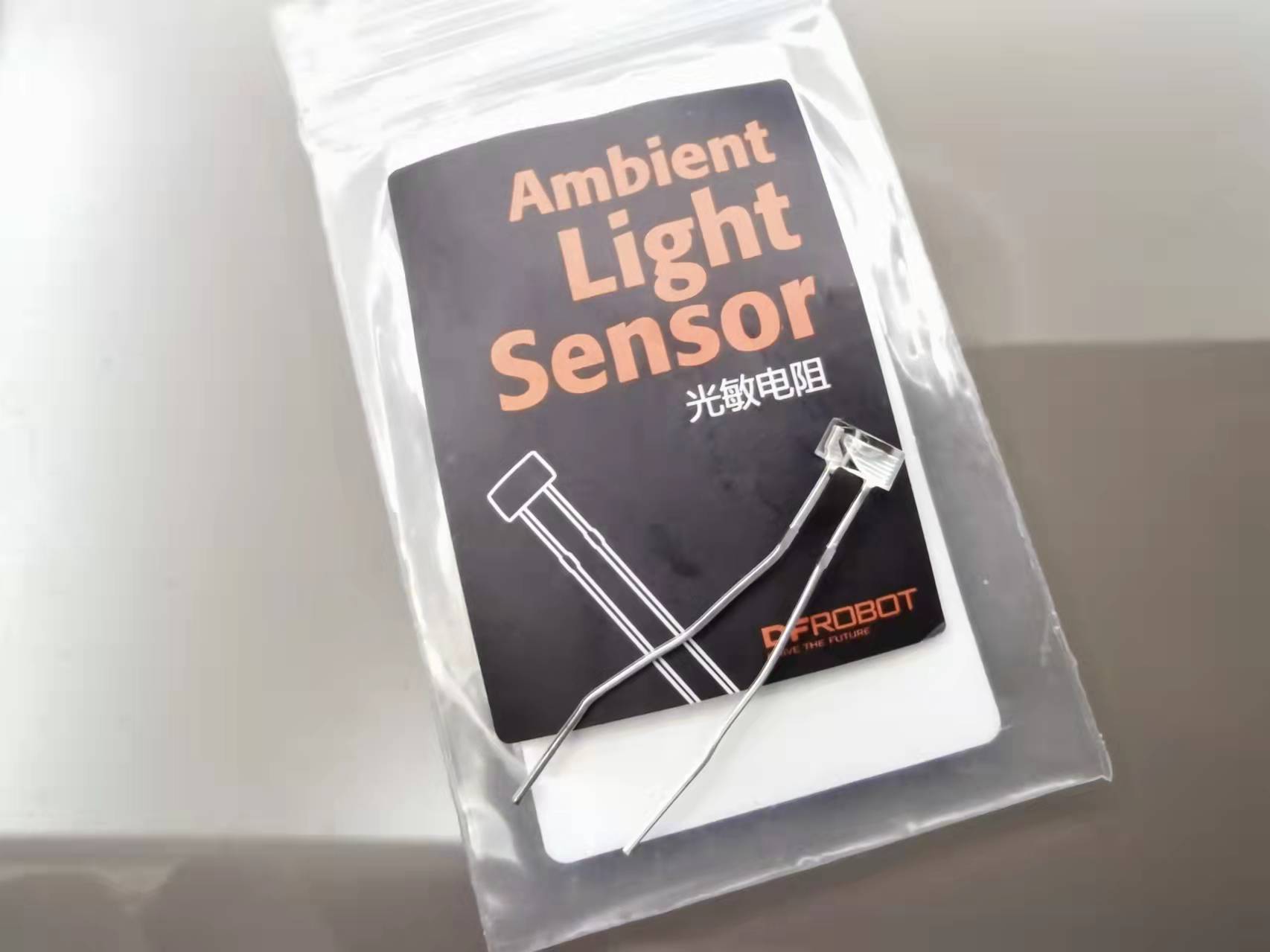
I did not find documentation for this sensor on the DFRobot website. Datasheet of Adafruit Industries LLC 161 What is a photoresistors?
A photoresistor (also known as a Photocell, or light-dependent resistor, LDR, or photo-conductive cell) is a passive component that decreases resistance with respect to receiving luminosity (light) on the component’s sensitive surface. The resistance of a photoresistor decreases with increase in incident l intensity; in other words, it exhibits photoconductivity.
What is a photodiode?
A photodiode is a light sensitive semiconductor. It is a type of photodetector capable of changing (or converting) light into either current or voltage, depending upon its connections. It is a diode and wired with reverse biasing so that when in the dark, only a small amount of current, known as dark current, will flow. When in the light, a current known as photocurrent flows through the diode.
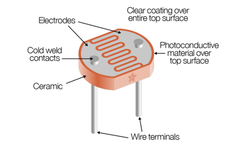
Structure
The structure of a photoresistor:
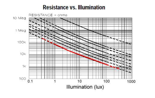
Resistance value
A photocell’s resistance changes as the face is exposed to more light. When its dark, the sensor looks like an large resistor up to 10MΩ, as the light level increases, the resistance goes down. This graph indicates approximately the resistance of the sensor at different light levels. Remember each photocell will be a little different, the graph is an example! Note that the graph is not linear, its a log-log graph!
Lux
What is lux?
The lux (symbol: lx) is the SI derived unit of illuminance, measuring luminous flux per unit area. It is equal to one lumen per square metre. In photometry, this is used as a measure of the intensity, as perceived by the human eye, of light that hits or passes through a surface. It is analogous to the radiometric unit watt per square metre, but with the power at each wavelength weighted according to the luminosity function, a standardized model of human visual brightness perception. In English, “lux” is used as both the singular and plural form.
| Illuminance | Example |
|---|---|
| 0.002 lux | Moonless clear night sky |
| 0.2 lux | Design minimum for emergency lighting (AS2293). |
| 0.27 - 1 lux | Full moon on a clear night |
| 3.4 lux | Dark limit of civil twilight under a clear sky |
| 50 lux | Family living room |
| 80 lux | Hallway/toilet |
| 100 lux | Very dark overcast day |
| 300 - 500 lux | Sunrise or sunset on a clear day. Well-lit office area. |
| 1,000 lux | Overcast day; typical TV studio lighting |
| 10,000 - 25,000 lux | Full daylight (not direct sun) |
| 32,000 - 130,000 lux | Direct sunlight |
Test
One Sensor
Test the light sensor:
void setup() {
  Serial.begin(9600);
  pinMode(A1, INPUT);
}

void loop() {
  int value = analogRead(A1); //Read value from light sensor
  value = map(value, 0, 1023, 0, 255);
  Serial.println(value);
  delay(100);
}
My board was fried last time when I do test output devices, so just use Arduino as an alternative.
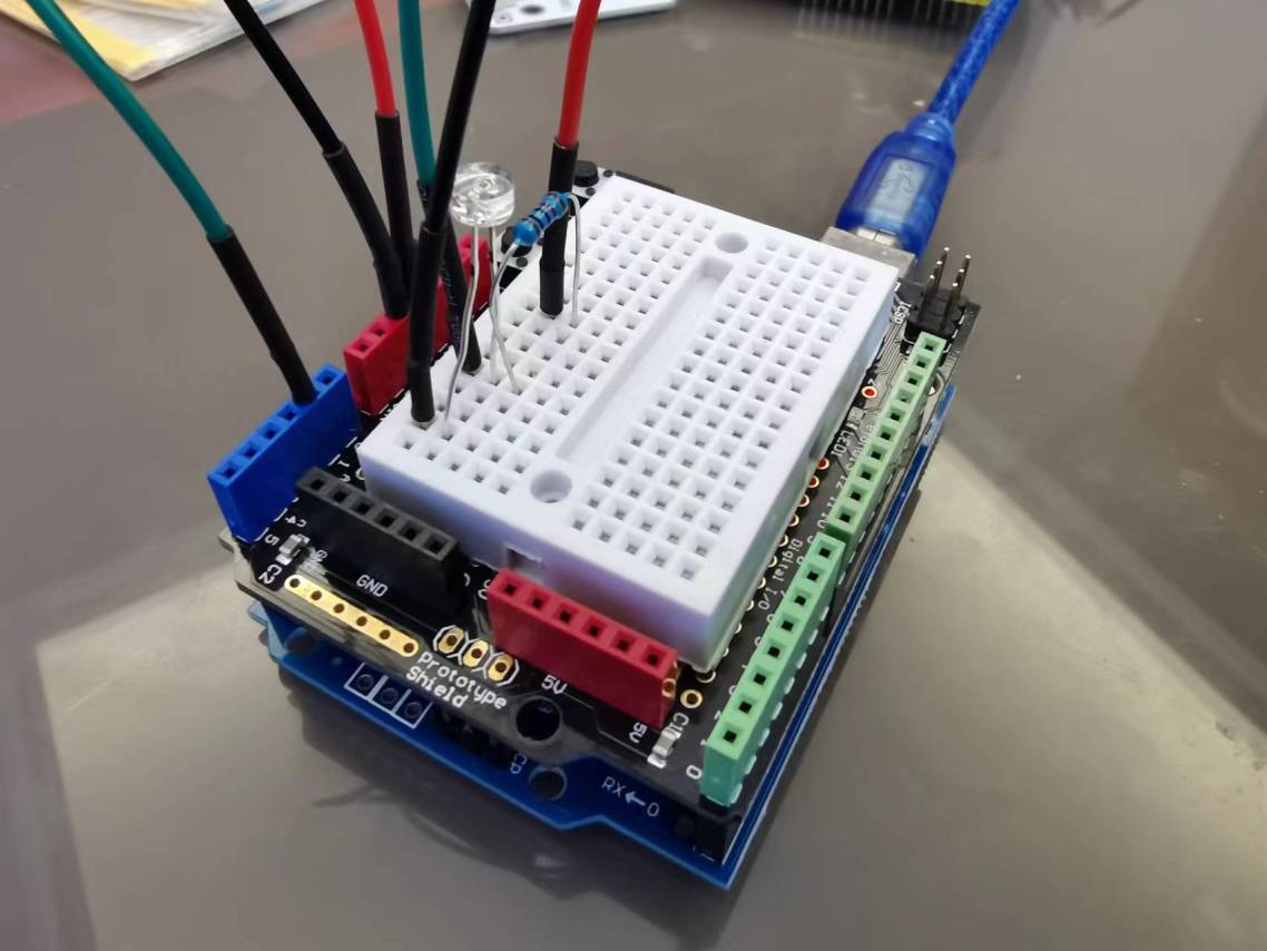
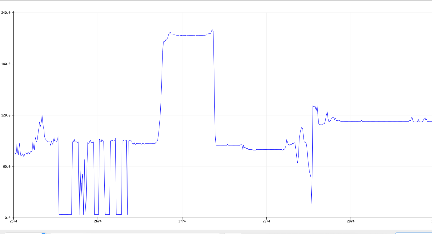
In Arduino > Tools > Serial Plotter, it can automaticly draw the result from seial console into a grid.
Two Sensors
In the output device week,I used a servo motor and a light sensor to make the small robot run away from light.
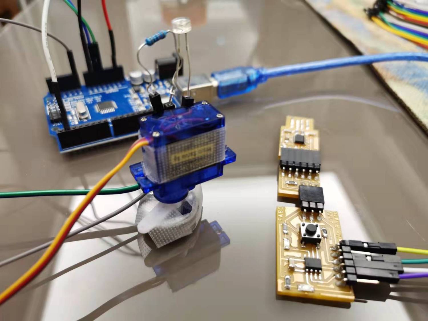
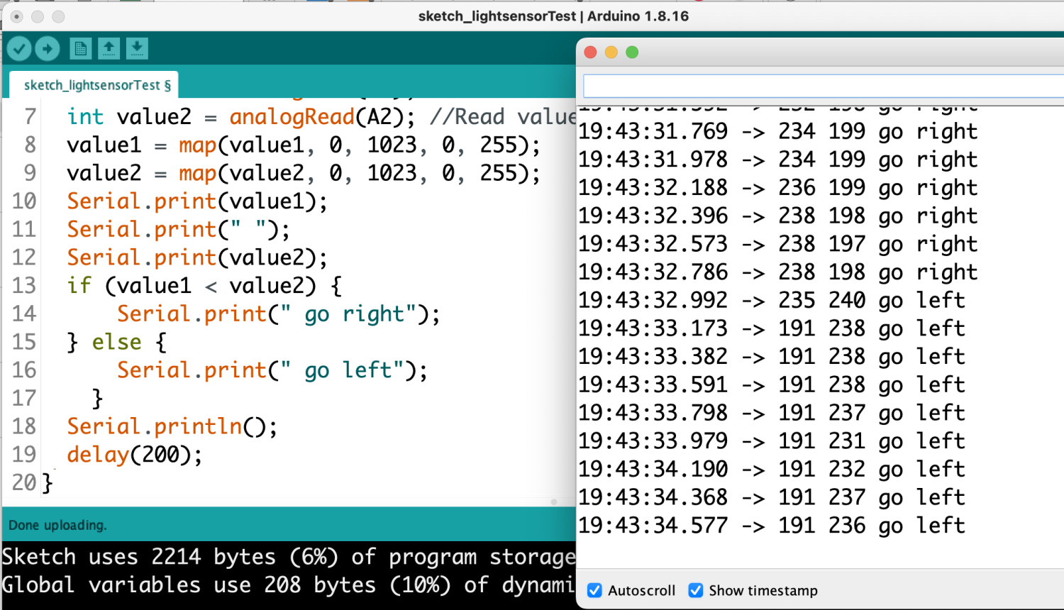
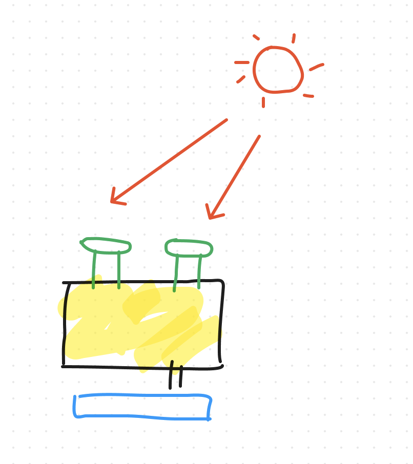
This time I want to make another robot that can chase the light. In order to do this, I need to use two photoresistors to identify the direction. In the picture the two green components are photoresistors. If the light from two sides are different, trun the motor twist to the higher side.
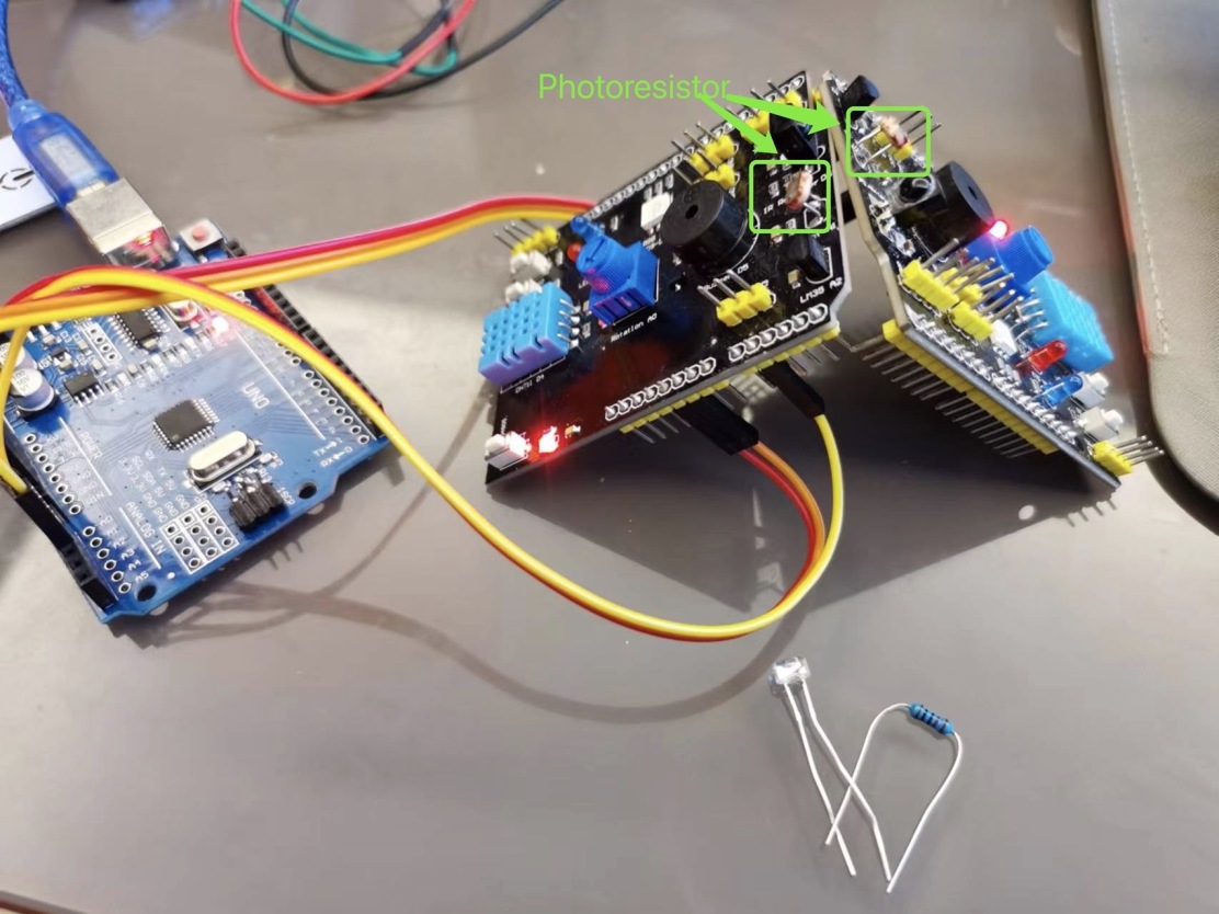
I found two light sensors on two arduino test board, so I tried to use these two together to do the experiment.
Update the program to test left and right: