9. Embedded Programming
TODO List
- Group assignment:
- Compare the performance and development workflows for other architectures
-
Document your work to the group work page and reflect on your individual page what you learned
-
Individual project
- Read the datasheet for your microcontroller
- Use your programmer to program your board to do something
Group assignment
The group asignment is to compare different architectures of microcontrollers. So we used Raspberry Pi 4 as our comparing object.
Raspberry Pi
Raspberry Pi is a tiny, dual-display, desktop computer.
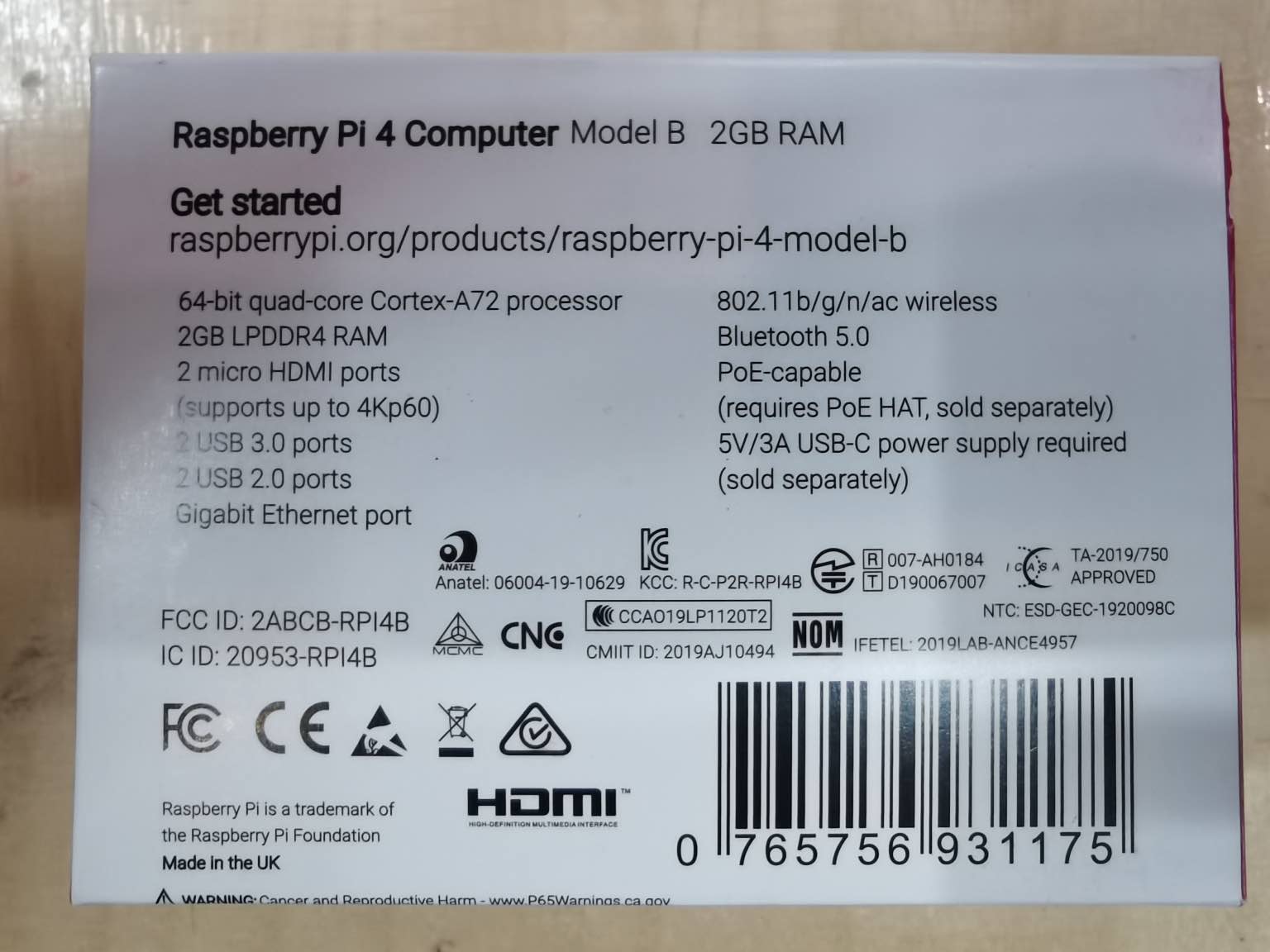
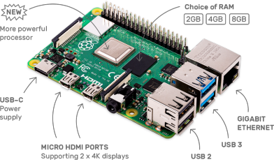
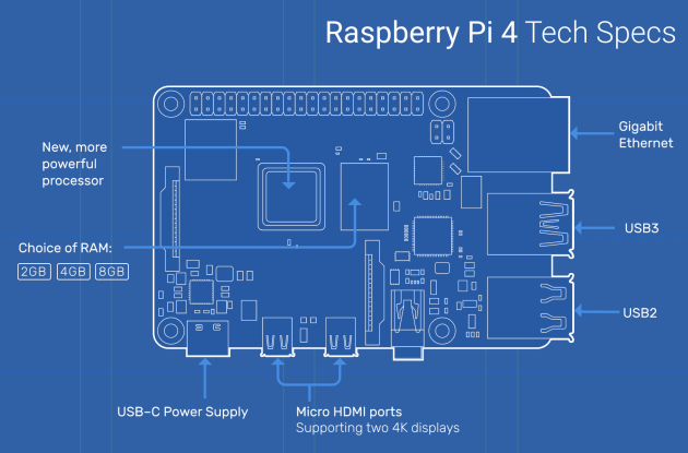
Here is some of the specifications, full list you can find here.
- Broadcom BCM2711, Quad core Cortex-A72 (ARM v8) 64-bit SoC @ 1.5GHz
- 2GB, 4GB or 8GB LPDDR4-3200 SDRAM (depending on model)
- 2.4 GHz and 5.0 GHz IEEE 802.11ac wireless, Bluetooth 5.0, BLE
- Gigabit Ethernet
- 2 USB 3.0 ports; 2 USB 2.0 ports.
- Raspberry Pi standard 40 pin GPIO header (fully backwards compatible with previous boards)
- 2 × micro-HDMI ports (up to 4kp60 supported)
Microcontroller
Broadcom BCM2711, Quad core Cortex-A72 (ARM v8) 64-bit SoC @ 1.5GHz
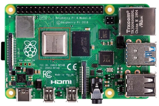
It is in the center of the board with the metal cover. The BCM2711 is a quad-core Cortex-A72 64-bit CPU which has a Videocore VI Graphics Processing Unit (GPU) handling all graphical input/output. Datasheet of BCN2711 is here. ARM processor is a RISC(Reduced Instruction Set Computer ) processor.
AddressMap
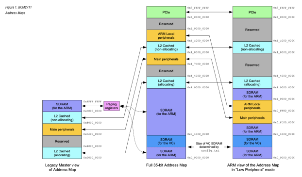
Addresses in ARM Linux are: 1. Issued as virtual addresses by the ARM core, then 2. Mapped into a physical address by the ARM MMU, then 3. Used to select the appropriate peripheral or location in RAM This is the typical way of Linux treating all the hardwares as virtual devices.
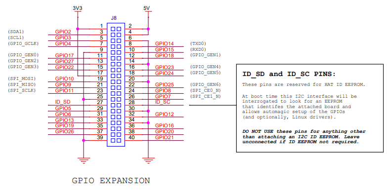
Raspberry Pi 4 partial schematic, the picture below is the schematic for the GPIO expansion on the borad. We used them in the proramming part.
Use raspberry Pi to program python
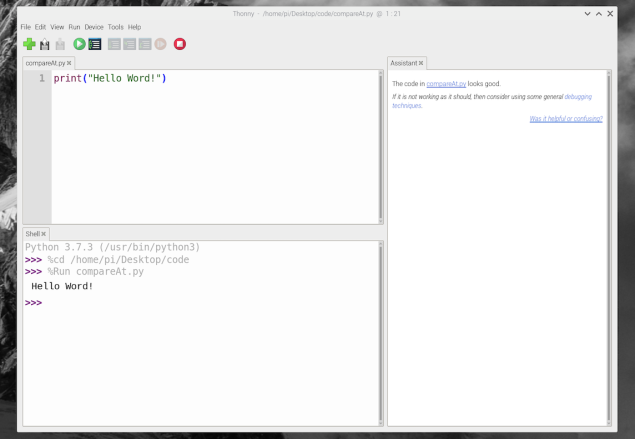
HelloWorld
We use the Thonny, it is a Python IDE comes with the raspberry system.
LED Blink
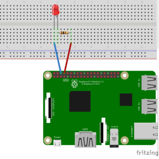
We followed this tutorial to do coding experiment. Use an LED and a resistor to connect to the GPIO ports.
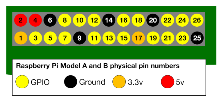
The upper image is only part of the ports in the GPIO expansion. We don’t dnow why the author use this one but it is kind of misleading. But with the schematic picture in the previous chapter you can see it is the left part of all the ports.
Connect the circuit like this:
import RPi.GPIO as GPIO    # Import Raspberry Pi GPIO library
from time import sleep     # Import the sleep function from the time module

GPIO.setwarnings(False)    # Ignore warning for now
GPIO.setmode(GPIO.BOARD)   # Use physical pin numbering
GPIO.setup(8, GPIO.OUT, initial=GPIO.LOW)   # Set pin 8 to be an output pin and set initial value to low (off)

while True: # Run forever
    GPIO.output(8, GPIO.HIGH) # Turn on
    sleep(1)                  # Sleep for 1 second
    GPIO.output(8, GPIO.LOW)  # Turn off
    sleep(1)
    # GPIO.output(8, GPIO.HIGH)
    # sleep(0.2)
    # GPIO.output(8, GPIO.LOW)
    # sleep(0.5)
    # GPIO.output(8, GPIO.HIGH)
    # sleep(0.2)
Finally we make the LED blink!
What I learned
Raspberry Pi4 is the same architecture as our processor Attiny412, which is also a RISC processor. Raspberry Pi runs Linux system. It is capable of doing much more things. Basically it is a personal computer with easier access to hardware programming.
Individual assignment
ATtiny212/412
The ATtiny212/412 microcontrollers are using the high-performance low-power AVR® RISC architecture, and is capable of running at up to 20MHz, with up to 2/4KB Flash, 128/256bytes of SRAM and 64/128bytes of EEPROM in a 8- pin package. The series uses the latest technologies with a flexible and low power architecture including Event System and SleepWalking, accurate analog features and advanced peripherals.
RISC
There are two kinds of computers in construction architecture. RISC: Reduced Instruction Set Computer CISC: Complex Instruction Set Computer Intel series CPU like the x86, have a rich instruction set capable of doing complex things with a single instruction. They are CISC. ATtiny212/412 is RISC.
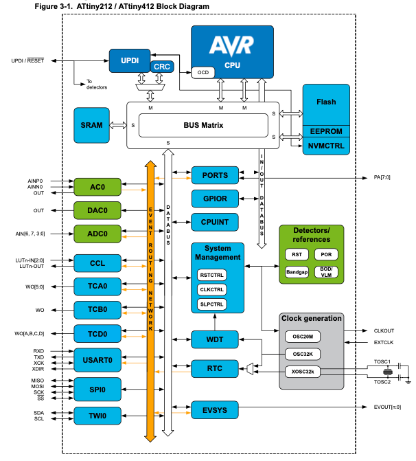
Block Diagram
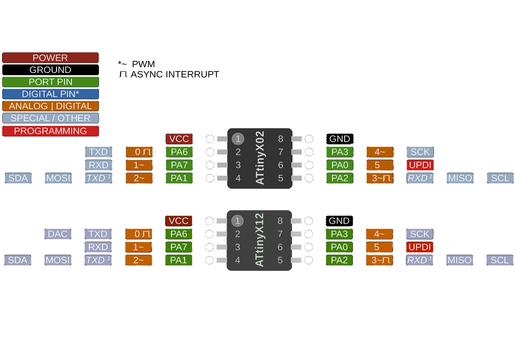
Pinout
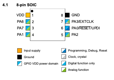
We use this diagram when writing code. The orange color pins are for digital and analog io. The numbers in orange rectangles are those we use in code like digigalWrite(4, HIGH); This is using PIN7-PA3-4~.
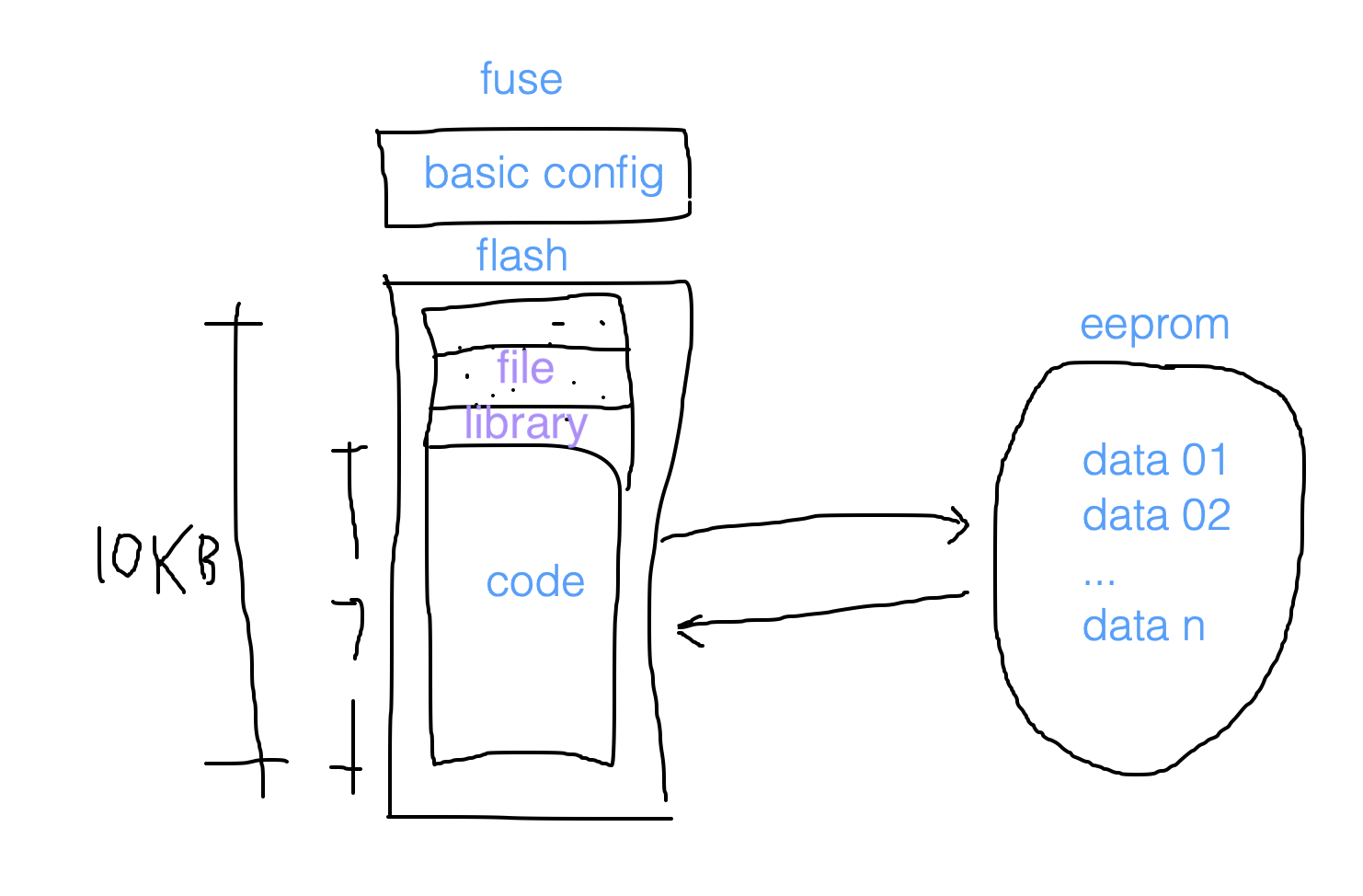
Memory
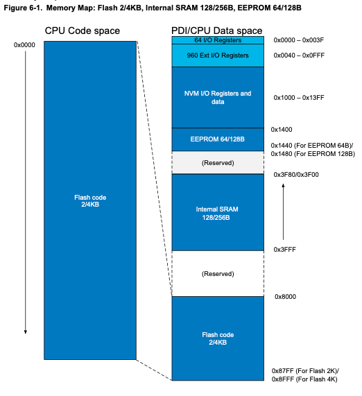
This is the hardest part to fully understand this diagram.
FLASH: ** SRAM: Static Random-Access Memory EEPROM: Electrically Erasable Programmable read only memory NVM I/O Registers and data:**
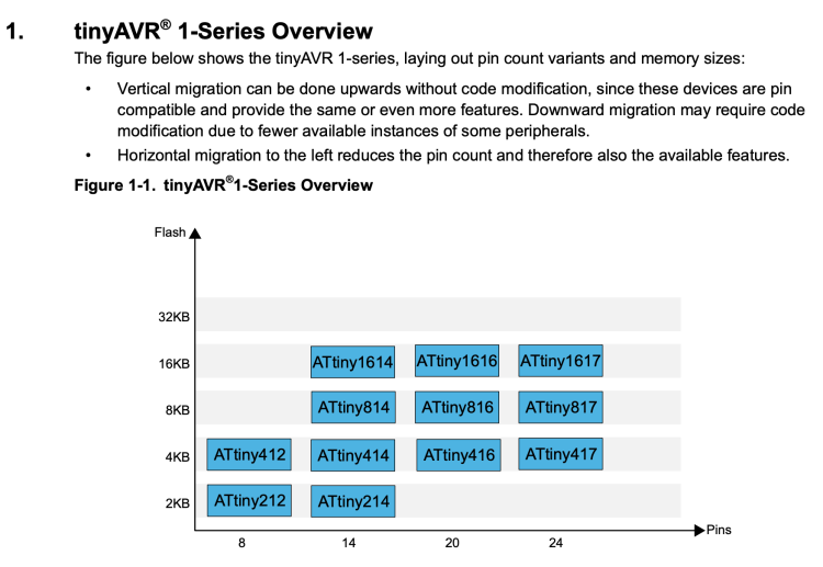
Vertical migration and Backwards migration
Finaly, I found this picture make upward migration、downward migration、forward migration and backward migration clear. In Chinese it is very difficult to identify which is which. 向前(Forward)migration,I always think of it as 从前,which is old times. It is totally the different direction of forward.
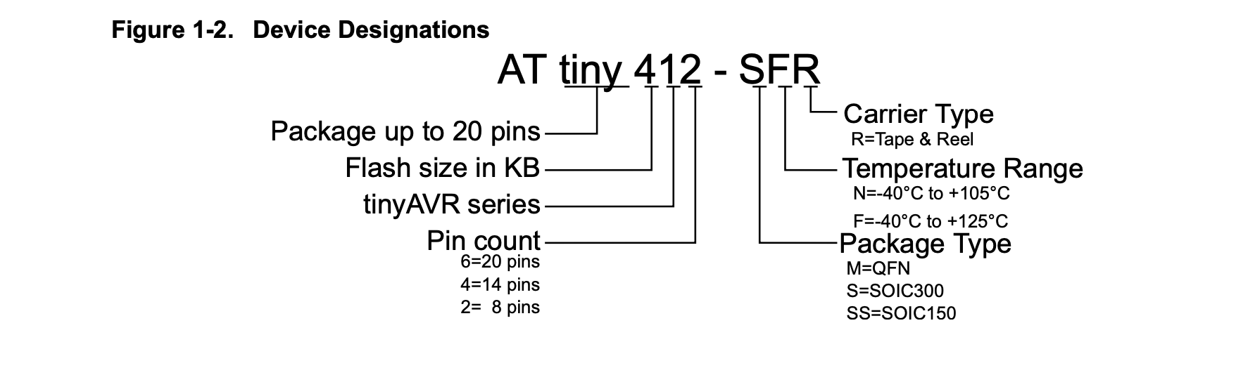
Explain the name of this device:
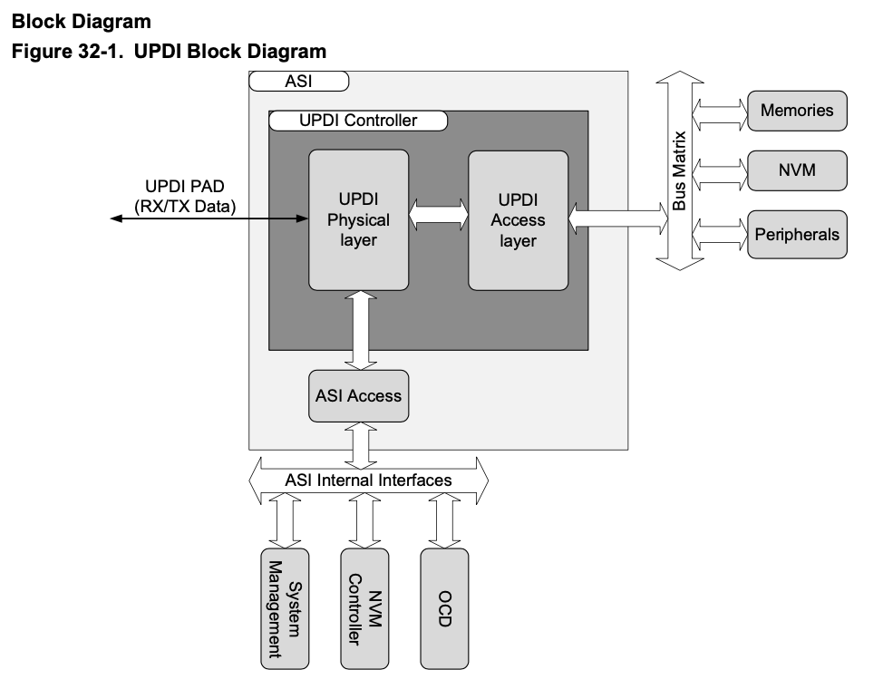
Language level and UPDI
There are different levels of programming language. machine language: (binary)Computer can understand and run directly. assembly language: use very simple command to write code like ADD, MOVE. advanced language: language designed for programmer to use and write code easily.
Some examples of assembly language:
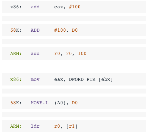
All the code goes into the board from UPDI(Unified Program and Debug Interface) interface of the Attiny chip.
NVM
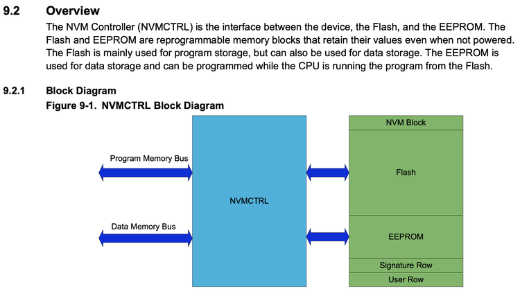
EEPROM
The EEPROM is divided into a set of pages where one page consists of multiple bytes. The EEPROM has byte granularity on erase write. Within one page, only the bytes marked to be updated will be erased/ written. The byte is marked by writing a new value to the page buffer for that address location.
Some other links
Run Arduino by P5js 【Failed】
I tried to follow this tutorial to set up the environment to make P5js to control Arduino. https://github.com/sarahghp/p5bots/blob/master/examples/HelloWorld.md The nodejs command is:
npm install -g p5bots-server
It results in nodejs errors :
npm WARN deprecated serialport@4.0.7: This version is no longer supported, to receive security updates and bug fixes upgrade to the latest version.
npm WARN deprecated json3@3.3.2: Please use the native JSON object instead of JSON 3
npm ERR! code 1
npm ERR! path /usr/local/lib/node_modules/p5bots-server/node_modules/serialport
npm ERR! command failed
npm ERR! command sh -c node-pre-gyp install --fallback-to-build
npm ERR! CXX(target) Release/obj.target/serialport/src/serialport.o
npm ERR!   CXX(target) Release/obj.target/serialport/src/serialport.o
npm ERR! Failed to execute '/usr/local/bin/node /usr/local/lib/node_modules/npm/node_modules/node-gyp/bin/node-gyp.js build --fallback-to-build --module=/usr/local/lib/node_modules/p5bots-server/node_modules/serialport/build/Release/serialport.node --module_name=serialport --module_path=/usr/local/lib/node_modules/p5bots-server/node_modules/serialport/build/Release' (1)
npm ERR! node-pre-gyp info it worked if it ends with ok
npm ERR! node-pre-gyp info using node-pre-gyp@0.6.32
npm ERR! node-pre-gyp info using node@14.16.0 | darwin | x64
npm ERR! node-pre-gyp info check checked for "/usr/local/lib/node_modules/p5bots-server/node_modules/serialport/build/Release/serialport.node" (not found)
npm ERR! node-pre-gyp http GET https://github.com/EmergingTechnologyAdvisors/node-serialport/releases/download/4.0.7/serialport-v4.0.7-node-v83-darwin-x64.tar.gz
npm ERR! node-pre-gyp http 404 https://github.com/EmergingTechnologyAdvisors/node-serialport/releases/download/4.0.7/serialport-v4.0.7-node-v83-darwin-x64.tar.gz
npm ERR! node-pre-gyp ERR! Tried to download(404): https://github.com/EmergingTechnologyAdvisors/node-serialport/releases/download/4.0.7/serialport-v4.0.7-node-v83-darwin-x64.tar.gz
npm ERR! node-pre-gyp ERR! Pre-built binaries not found for serialport@4.0.7 and node@14.16.0 (node-v83 ABI) (falling back to source compile with node-gyp)
npm ERR! node-pre-gyp http 404 status code downloading tarball https://github.com/EmergingTechnologyAdvisors/node-serialport/releases/download/4.0.7/serialport-v4.0.7-node-v83-darwin-x64.tar.gz
npm ERR! node-pre-gyp ERR! Tried to download(undefined): https://github.com/EmergingTechnologyAdvisors/node-serialport/releases/download/4.0.7/serialport-v4.0.7-node-v83-darwin-x64.tar.gz
Acutally the project was already abandoned. This does not work.
There is WebUSB project I found which is said it can solve this problem, I haven’t enought time to try it. Just mark here. https://github.com/monteslu/p5.j5
What is WebUSB ? It is the experimental technology. WebUSB API provides attributes and methods for finding and connecting USB devices from a web page. Not all the browsers have this api. https://developer.mozilla.org/en-US/docs/Web/API/USB
JohnnyFive
Since I have familar with the Arduino IDE and C programing. I want to try some different program to make the arduino run. When I was trying to solve the p5bots problem, I found this J5 site.

Johnny-Five(J5) is the JavaScript Robotics & IoT Platform. Originally created by Rick Waldron in 2012, Johnny-Five is maintained by a community of passionate software developers and hardware engineers. Over 75 developers have made contributions towards building a robust, extensible and composable ecosystem.
Links
MainSite http://johnny-five.io/ GitHub Page https://github.com/rwaldron/johnny-five
Steps
Here are the 4 steps to run J5:
- Install Node.js .
- Setup your board.
- Get Johnny-Five: npm install johnny-five
- Run your program! node blink.js
blink.js
const {Board, Led} = require("johnny-five");
const board = new Board();

board.on("ready", () => {
  const led = new Led(13);
  led.blink(1000);
});
Run the program
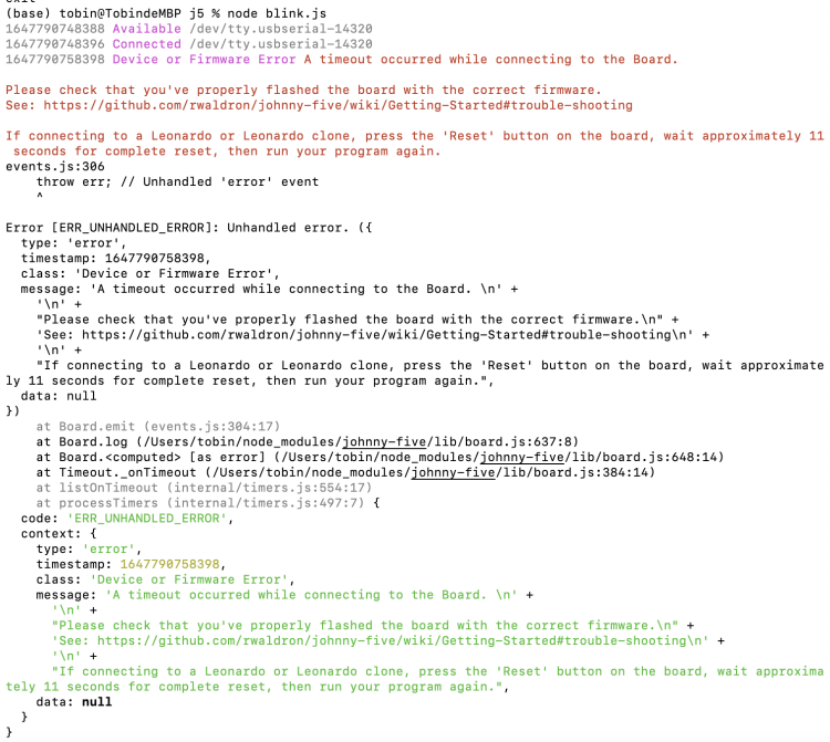
At first run of node blink.js, it came up with a lot errors:
(base) tobin@TobindeMBP j5 % node blink.js
1647790748388 Available /dev/tty.usbserial-14320
1647790748396 Connected /dev/tty.usbserial-14320
1647790758398 Device or Firmware Error A timeout occurred while connecting to the Board.

Please check that you've properly flashed the board with the correct firmware.
See: https://github.com/rwaldron/johnny-five/wiki/Getting-Started#trouble-shooting

If connecting to a Leonardo or Leonardo clone, press the 'Reset' button on the board, wait approximately 11 seconds for complete reset, then run your program again.
events.js:306
    throw err; // Unhandled 'error' event
    ^

Error [ERR_UNHANDLED_ERROR]: Unhandled error. ({
  type: 'error',
  timestamp: 1647790758398,
  class: 'Device or Firmware Error',
  message: 'A timeout occurred while connecting to the Board. \n' +
    '\n' +
    "Please check that you've properly flashed the board with the correct firmware.\n" +
    'See: https://github.com/rwaldron/johnny-five/wiki/Getting-Started#trouble-shooting\n' +
    '\n' +
    "If connecting to a Leonardo or Leonardo clone, press the 'Reset' button on the board, wait approximately 11 seconds for complete reset, then run your program again.",
  data: null
})
    at Board.emit (events.js:304:17)
    at Board.log (/Users/tobin/node_modules/johnny-five/lib/board.js:637:8)
    at Board.<computed> [as error] (/Users/tobin/node_modules/johnny-five/lib/board.js:648:14)
    at Timeout._onTimeout (/Users/tobin/node_modules/johnny-five/lib/board.js:384:14)
    at listOnTimeout (internal/timers.js:554:17)
    at processTimers (internal/timers.js:497:7) {
  code: 'ERR_UNHANDLED_ERROR',
  context: {
    type: 'error',
    timestamp: 1647790758398,
    class: 'Device or Firmware Error',
    message: 'A timeout occurred while connecting to the Board. \n' +
      '\n' +
      "Please check that you've properly flashed the board with the correct firmware.\n" +
      'See: https://github.com/rwaldron/johnny-five/wiki/Getting-Started#trouble-shooting\n' +
      '\n' +
      "If connecting to a Leonardo or Leonardo clone, press the 'Reset' button on the board, wait approximately 11 seconds for complete reset, then run your program again.",
    data: null
  }
}
With the help of this link:
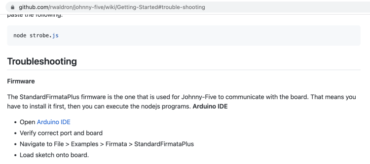
Run the firmata to the board first:
- Navigate to File > Examples > Firmata > StandardFirmataPlus
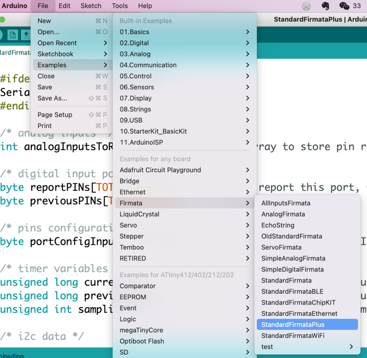
Then the led blink works!
Remark
BTW it is important to use exit to exit the node enviroment. With out this step, code in the Arduino IDE will not be able to uploaded to the board and run.
(base) tobin@TobindeMBP j5 % node blink.js
1647791413814 Available /dev/tty.usbserial-14320
1647791413823 Connected /dev/tty.usbserial-14320
1647791414654 Repl Initialized
>>
(To exit, press Ctrl+C again or Ctrl+D or type .exit)
>>
1647791421405 Board Closing.
(base) tobin@TobindeMBP j5 %
Try to upload Arduino code without quit j5 in consle will cause error.
Arduino Code
void setup() {
  // put your setup code here, to run once:
  pinMode(13, OUTPUT);
}

void loop() {
  // put your main code here, to run repeatedly:
  digitalWrite(13, HIGH);
  delay(1000);
  digitalWrite(13, LOW);
  delay(1000);
}
Arduino Error
avrdude: ser_open(): can’t open device “/dev/cu.usbserial-14320”: Resource busy Problem uploading to board. See https://support.arduino.cc/hc/en-us/sections/360003198300 for suggestions.
Arduino IDE
LED blink in random
int ledpin = 4;
int cnt = 100;
int leddata[100];

void setup() {
  pinMode(ledpin, OUTPUT);
  //Serial.begin(9600);
  //Generate random numbers here
  for (int i =0; i<cnt; i++) {
    leddata[i]= random(2);
    //Serial.println(leddata[i]);
  }
}

void loop() {
  for (int i =0; i< cnt; i++) {
    if (leddata[i] == 1) {
      ledblink(ledpin);
    } else {
      lednoblink(ledpin);
    }
  }
}

void ledblink(int pin) {
  digitalWrite(pin, HIGH);
  delay(100);
  digitalWrite(pin, LOW);
  delay(100);
}

void lednoblink(int pin) {
  digitalWrite(pin, LOW);
  delay(200);
}
It works both on arduinio and my board.
LED controlled by button
The idea of this program is to still make the led blinking in random. But the difference from the previous on is that the blinking is controlled by the button. Once the button is clicked, the led will toggle between blinking and not blinking.
int ledpin = 4;
int btnpin = 3;
int cnt = 50;
int leddata[50];
int index = 0;
int onoff = 0;
int value = 0;
int pvalue = 0;
int pcount = 0;

void setup() {
  Serial.begin(9600);
  pinMode(ledpin, OUTPUT);
  pinMode(btnpin, INPUT);
  for (int i = 0; i < cnt; i++) {
    leddata[i] = random(2);
  }
}


void loop() {
  value = digitalRead(btnpin);
  Serial.println("value");
  Serial.println(value);
  if (value != pvalue) {
      pcount ++;
  }
  if (pcount == 2) {
      //each button click has a process of go down and go up, change twice.
      onoff = (onoff + 1) % 2;
      pcount = 0;
  }
  Serial.println("onoff");
  Serial.println(onoff);

  if (leddata[index] == 1) {
    ledblink(ledpin);
  } else {
    lednoblink(ledpin);
  }
  index ++;
  if (index == cnt) {
    index = 0;
  }

  //delay(1000);
  pvalue = value;
}

void ledblink(int pin) {
  if (onoff == 0) {
    return;
  }
  digitalWrite(pin, HIGH);
  delay(100);
  digitalWrite(pin, LOW);
  delay(100);
}

void lednoblink(int pin) {
  digitalWrite(pin, LOW);
  delay(200);
}
作者:范东同学 链接:https://www.jianshu.com/p/0742bb15c2dd 来源:简书 著作权归作者所有。商业转载请联系作者获得授权,非商业转载请注明出处。
Issue Tracking
- When uploading program to the hello board, it is highly possible to have errors:
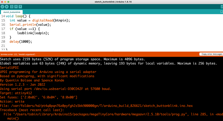
Error details:
SerialUPDI
UPDI programming for Arduino using a serial adapter
Based on pymcuprog, with significant modifications
By Quentin Bolsee and Spence Konde
Version 1.2.3 - Jan 2022
Using serial port /dev/cu.usbserial-D30CO4ZF at 57600 baud.
Target: attiny412
Set fuses: ['2:0x02', '6:0x04', '8:0x00']
Action: write
File: /var/folders/hd/pt4q8pqn76z0pyfgh2s5bk900000gn/T/arduino_build_826621/sketch_buttonblink.ino.hex
Traceback (most recent call last):
  File "/Users/tobin/Library/Arduino15/packages/megaTinyCore/hardware/megaavr/2.5.10/tools/prog.py", line 285, in <module>
    main()
  File "/Users/tobin/Library/Arduino15/packages/megaTinyCore/hardware/megaavr/2.5.10/tools/prog.py", line 128, in main
    return_code = pymcuprog_basic(args, fuses_dict)
  File "/Users/tobin/Library/Arduino15/packages/megaTinyCore/hardware/megaavr/2.5.10/tools/prog.py", line 199, in pymcuprog_basic
    status = pymcu._start_session(backend,
  File "/Users/tobin/Library/Arduino15/packages/megaTinyCore/hardware/megaavr/2.5.10/tools/libs/pymcuprog/pymcuprog_main.py", line 545, in _start_session
    backend.start_session(sessionconfig)
  File "/Users/tobin/Library/Arduino15/packages/megaTinyCore/hardware/megaavr/2.5.10/tools/libs/pymcuprog/backend.py", line 359, in start_session
    self.programmer.setup_device(
  File "/Users/tobin/Library/Arduino15/packages/megaTinyCore/hardware/megaavr/2.5.10/tools/libs/pymcuprog/programmer.py", line 78, in setup_device
    self.device_model = get_nvm_access_provider(self.transport,
  File "/Users/tobin/Library/Arduino15/packages/megaTinyCore/hardware/megaavr/2.5.10/tools/libs/pymcuprog/nvm.py", line 42, in get_nvm_access_provider
    accessprovider = NvmAccessProviderSerial(transport, device_info, baud=frequency)
  File "/Users/tobin/Library/Arduino15/packages/megaTinyCore/hardware/megaavr/2.5.10/tools/libs/pymcuprog/nvmserialupdi.py", line 53, in __init__
    self.avr = UpdiApplication(port, baud, self.dut)
  File "/Users/tobin/Library/Arduino15/packages/megaTinyCore/hardware/megaavr/2.5.10/tools/libs/pymcuprog/serialupdi/application.py", line 70, in __init__
    self.phy = UpdiPhysical(serialport, baud_temp)
  File "/Users/tobin/Library/Arduino15/packages/megaTinyCore/hardware/megaavr/2.5.10/tools/libs/pymcuprog/serialupdi/physical.py", line 29, in __init__
    self.initialise_serial(self.port, self.baud)
  File "/Users/tobin/Library/Arduino15/packages/megaTinyCore/hardware/megaavr/2.5.10/tools/libs/pymcuprog/serialupdi/physical.py", line 50, in initialise_serial
    self.ser.open()
  File "/Users/tobin/Library/Arduino15/packages/megaTinyCore/hardware/megaavr/2.5.10/tools/libs/serial/serialposix.py", line 272, in open
    self._reconfigure_port(force_update=True)
  File "/Users/tobin/Library/Arduino15/packages/megaTinyCore/hardware/megaavr/2.5.10/tools/libs/serial/serialposix.py", line 435, in _reconfigure_port
    termios.tcsetattr(
An error occurred while uploading the sketch
termios.error: (22, 'Invalid argument')
- Serial output is not stable when debugging. The joint is not stable, when I touch the board, the consle will lost connection, while the led and button is still work.