5. Electronics production
This week we are learning about PCB(Printed Circuit Board) production. We learn how to fabricate our own PCBs. We learn about these params when operating the mill machine:document feeds, speeds, plunge rate, depth of cut (traces and outline) and tooling. With the PCBs we need to solder tiny compoments on top of them and make them work.
Group Work
TODO
UPDI board
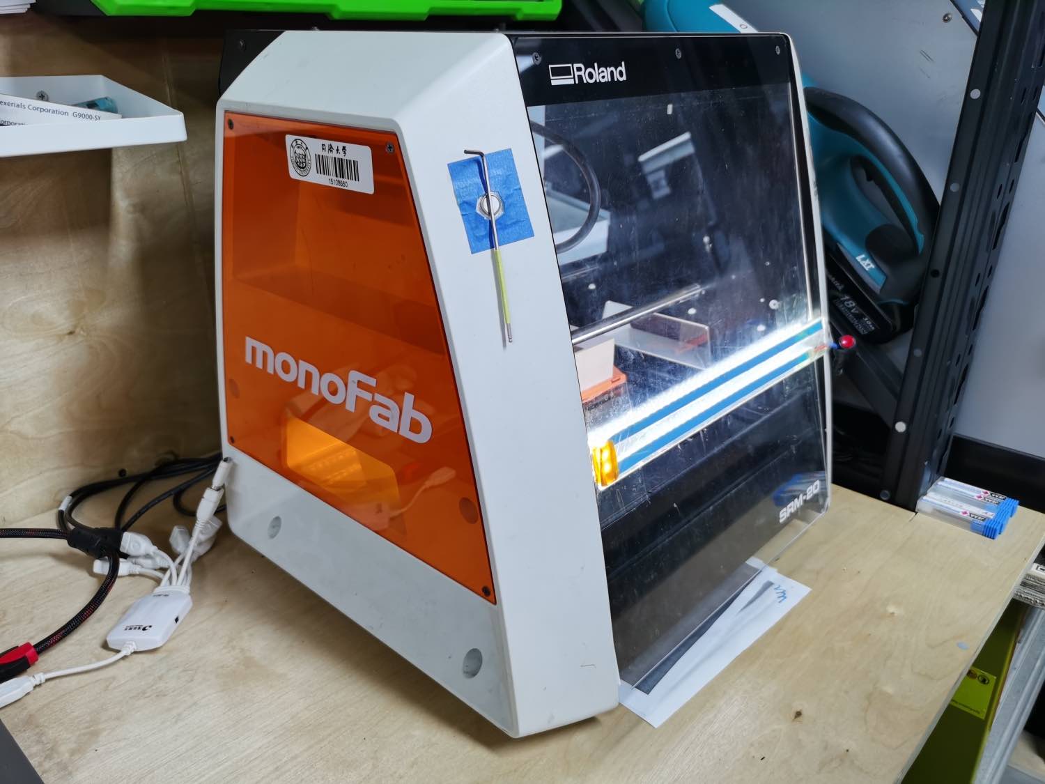
0. Machine-Roland Modela (SRM-20)
SRM-20 is one rapid compact reduction milling prototype machine.
It can be used to produce vivid parts and prototype products. This product is simple and convenient to use, suitable for office, home or teaching environment. The materials it can cut include: wax mold, chemical Wood, foam material, acrylic, polyvinyl acetate, ABS and PC board.
1. File prepration
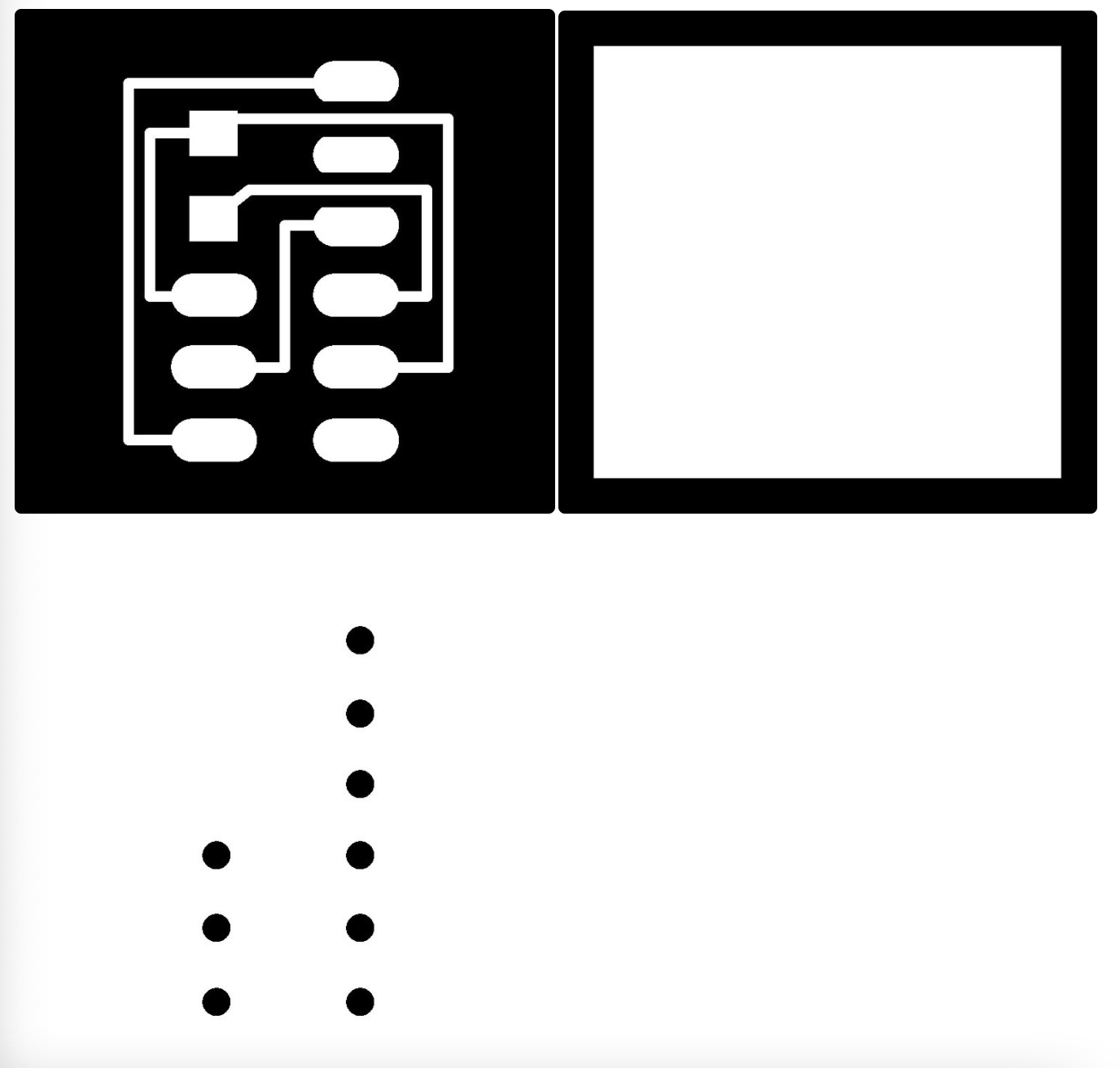
We need to cut an UPDI board and a test board.
 We get these files from Saverio. They are a little bit different from the files of the website provides.
We have three png images, including another one:
We get these files from Saverio. They are a little bit different from the files of the website provides.
We have three png images, including another one:
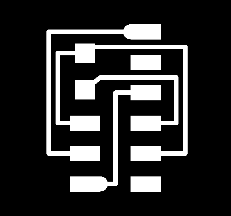
- traces
- holes drill
- outline
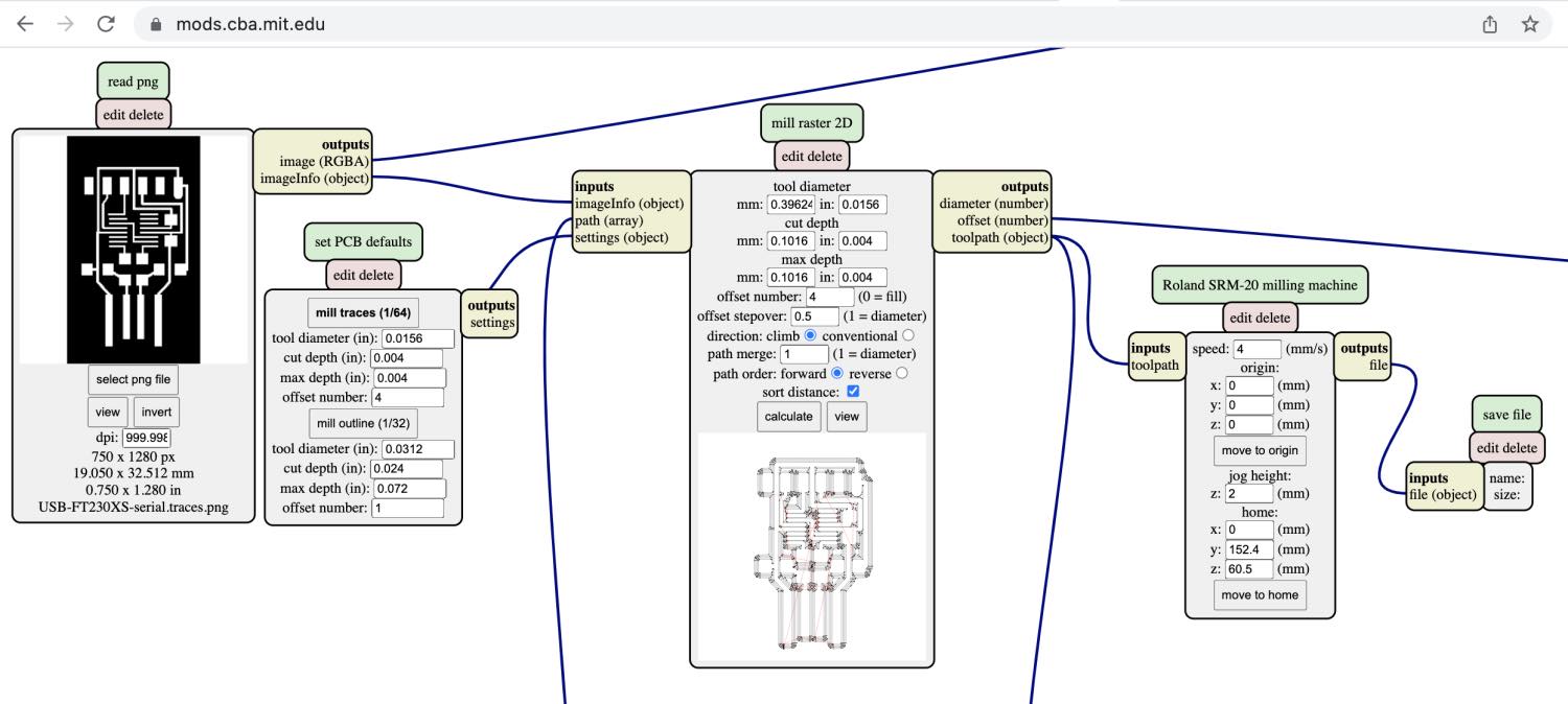
2. Generate File1 Traces
- Open mods in the browser.
- Right click on empty spaces.
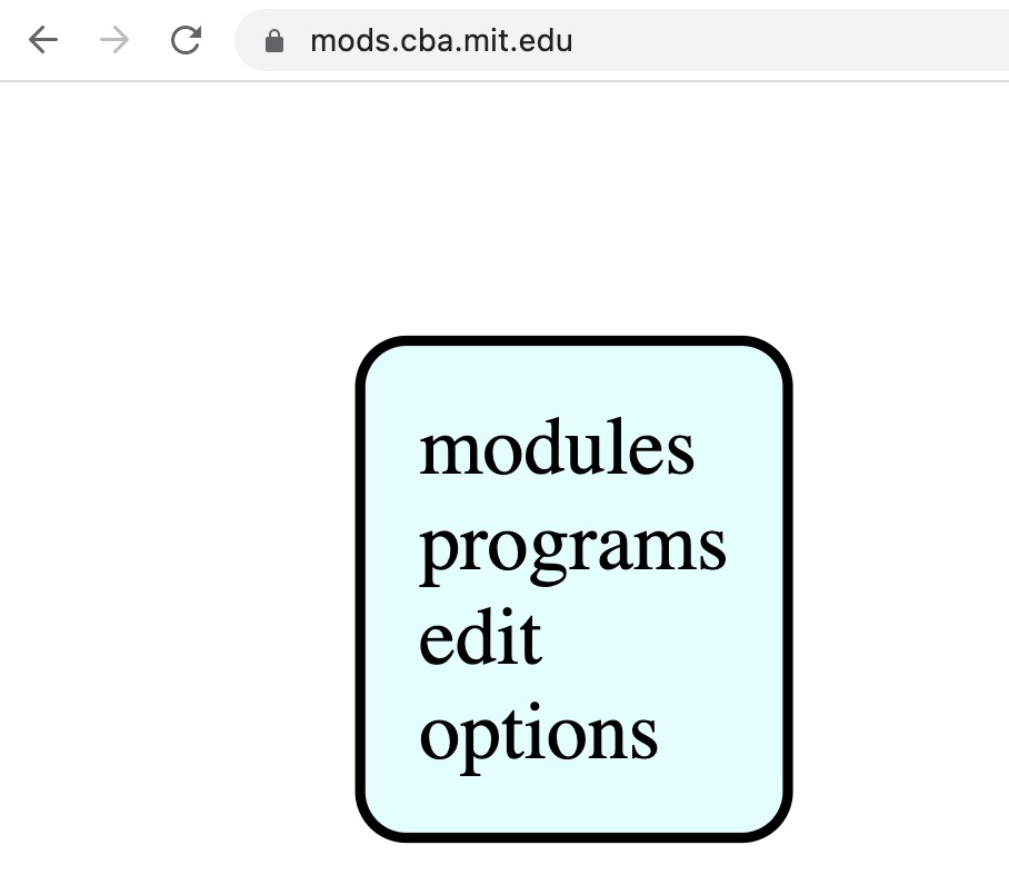
- Click programs.
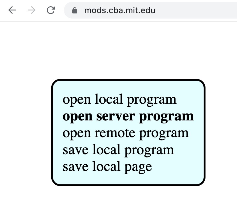
- Click open server program.
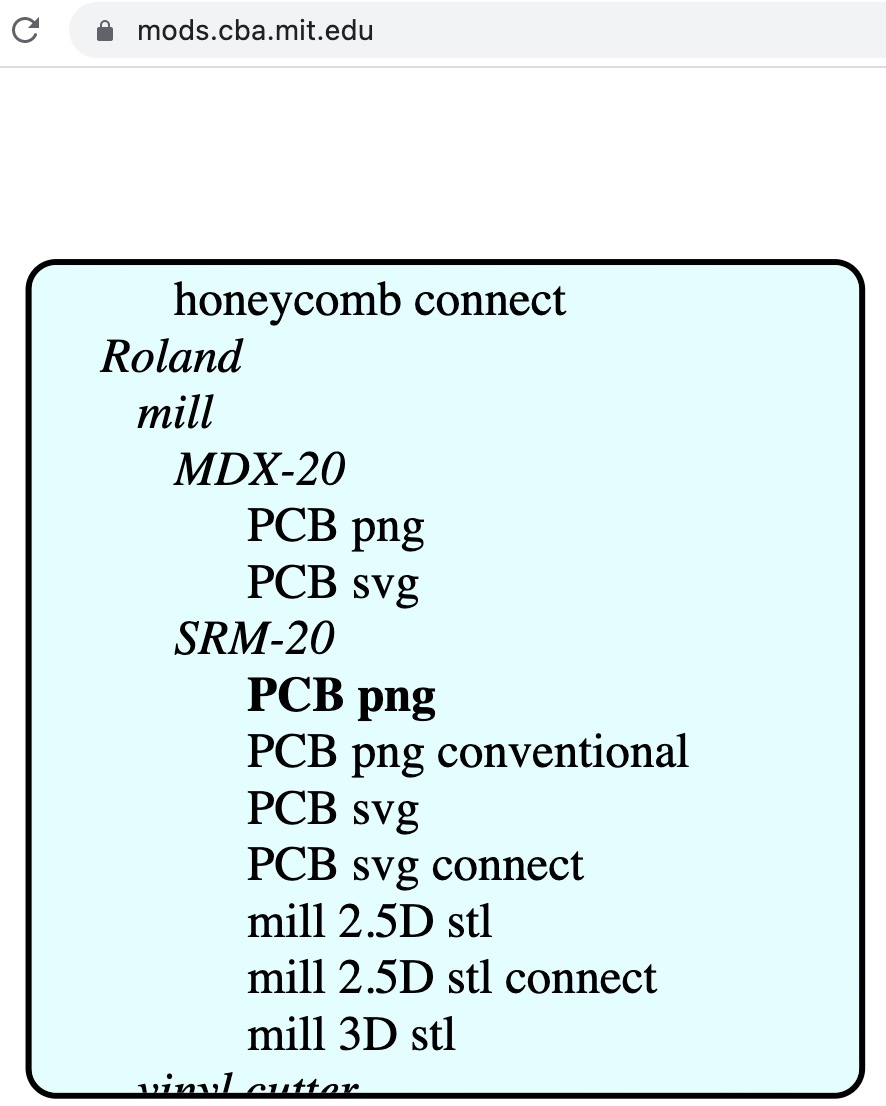
- Click Roland > mill > SRM-20 > png
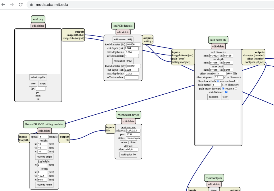
- In the first module of read png, select the trace file of png image.
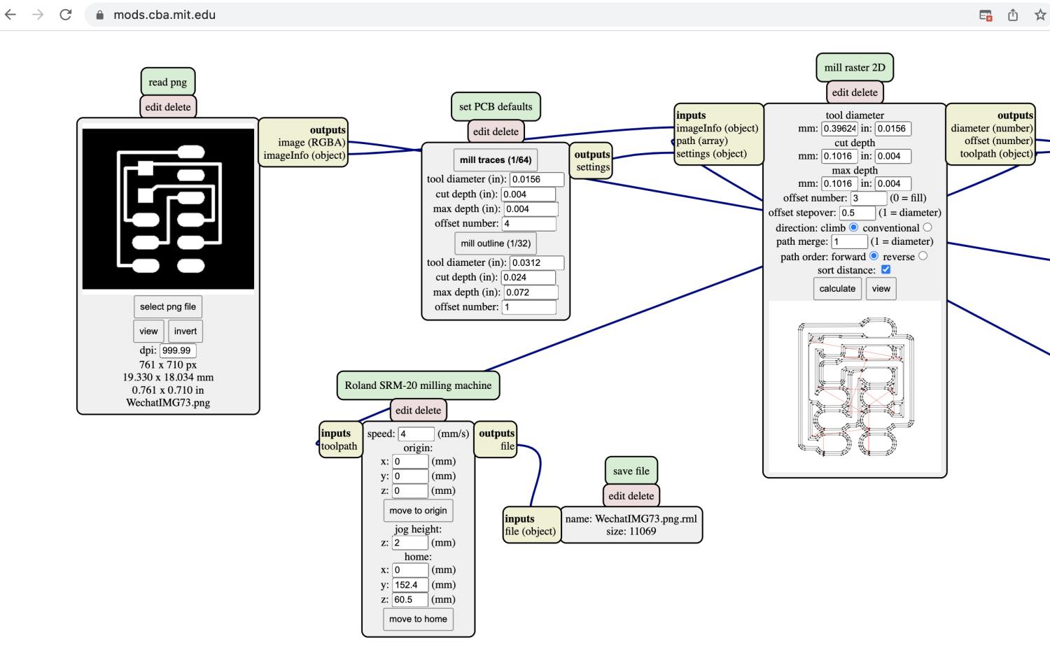
- Change the module params:
- read png module: Make sure the dpi is 1000 and the size is correct
- set PCB module: Select mill traces(1/64)
- Rolabd SRM-20 milling machine module: Set origin x, y, z to 0 mm.
Impoartant Params: tool diameter, cut depth, offset number, offset stepover, origin xyz, jog height, home xyz;
- Add a new module after Rolabd SRM-20 milling machine by right click on output file > modules > open server module > save file, connect the inputs to outputs together.
- Click calculate button and it will generate a .rml file.
3. Generate File2 Interior
Use the border file and go through the step2 process. Select mill outline in second module.
4. Generate File3 Holes
Use the hole image file and go through the step3 process.
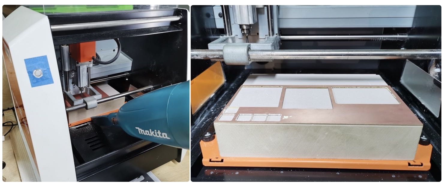
5. Prepare the Modela
Turn on Roland Modela and the computer and open VPanel for SRM-20.
 Now start to prepare the board and base.
- Get a circuit board blank ready. Clean off the dust and fingerprints.
- Press the “view” button on the Modela to toggle between loading and loaded positions.
- There should be a piece of wood/acryl( We use a chemical brick.) taped down on the machine securely already.
Clean the residues of any dust or particles.
- Place and press the board down on the sacrificial board securely with special made double side tape
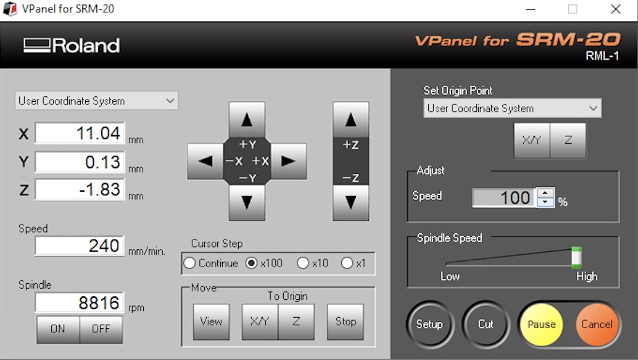
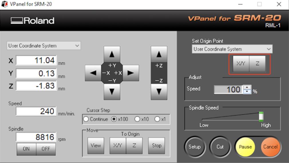
6. Set Origin XYZ
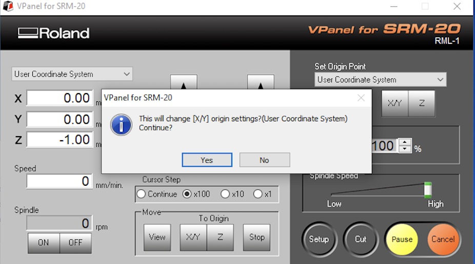
Move the machine to its position by using the X/Y arrows in VPanel for SRM-20 depends on the use of the board. When you have choosen the position click on Set origin X/Y in Vpanel.
 Set Z take more steps:
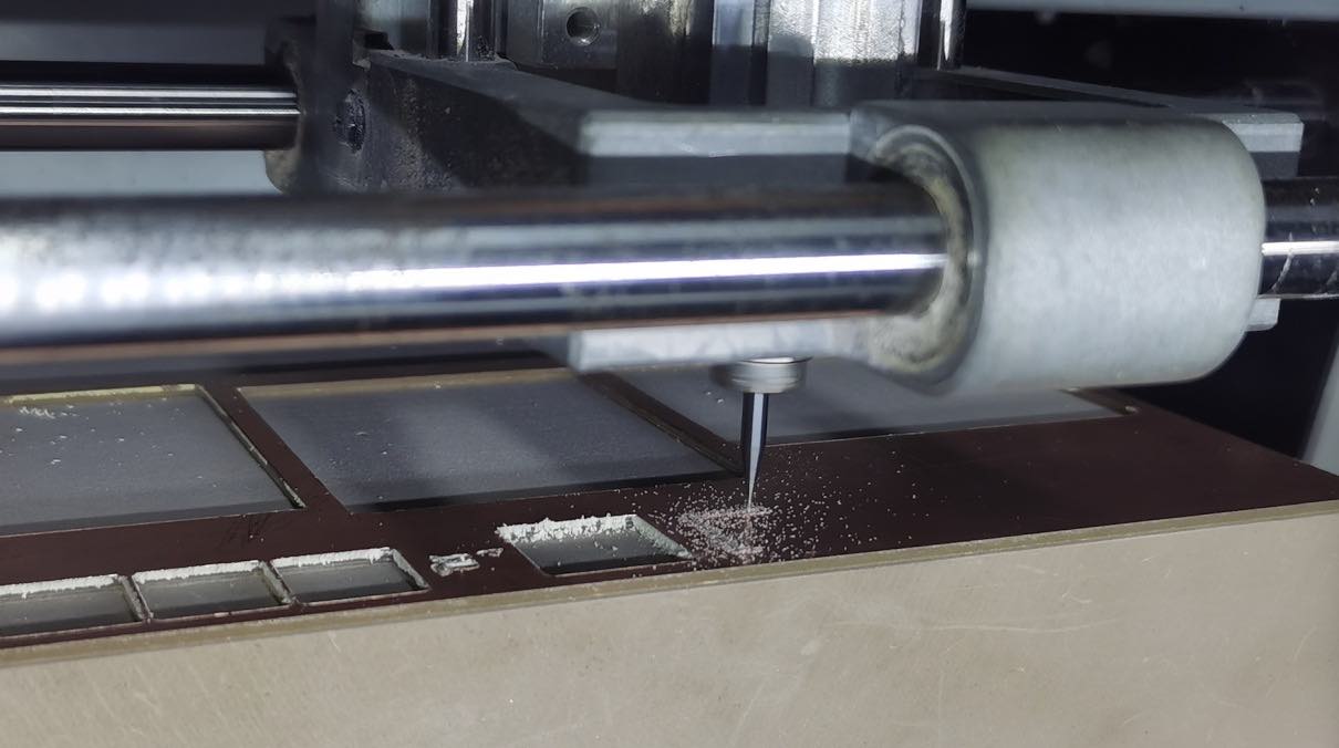
- Move the Z slowly with the control panel around 3-5 mm above the PCB plate. By loosing the collect screw and land the endmill on the surface. If the screw hole is bolcked by the bar, you can move Z up or down a little. But pay a lot attention that the mill do not hit the board or it will break.
- Slowly loosen the mill bit with an allen wrench so that it drops gently to the surface of your board.
Don’t let the endmill fall free on the surface or it can break.
- Tight the endmill with the screw on the collet.
- Now save the Z origin in the Vpanel control panel. It shows like when saving the XY origin.
Important: Move up Z immiadiately.
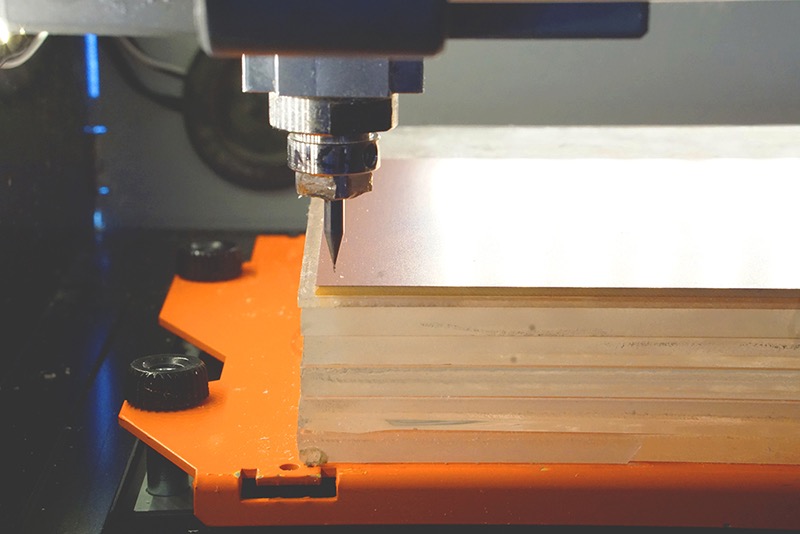
7. Cut the trace
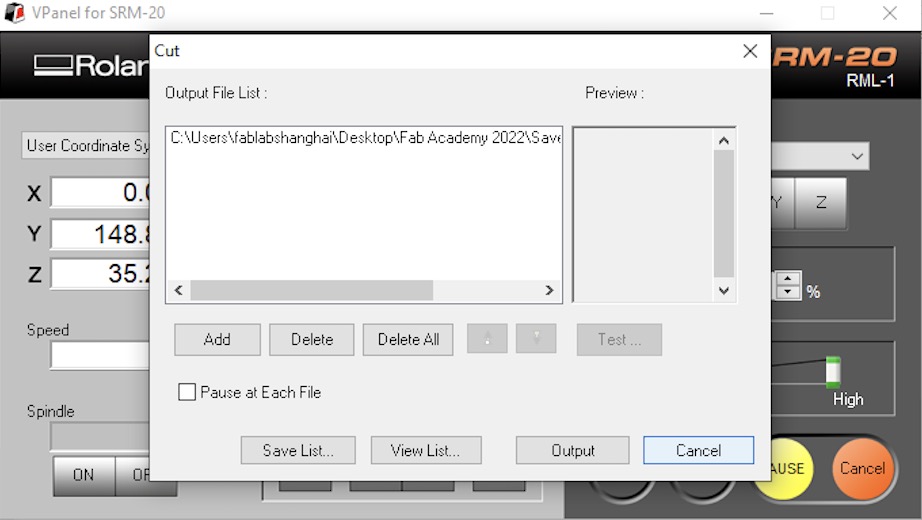
Click “Cut” on the control panel. Select the file we have and it will start to cut.
 You can change the speed to a low value and observe wether it is working correctly.
Click on Pause and View to make the machine send the borad to view position.
You can change the speed to a low value and observe wether it is working correctly.
Click on Pause and View to make the machine send the borad to view position.
8. Cut the border and holes
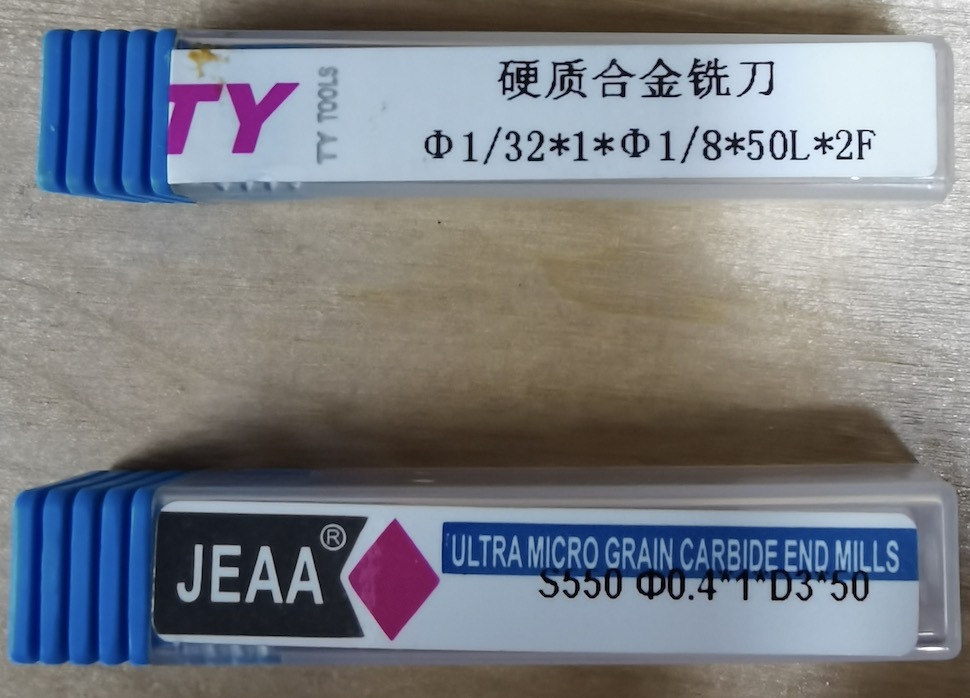
Keep the board and keep the XY origin. We change the end mill to 1/32 end mill and reset the Z origin.
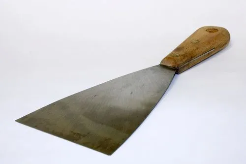
 After it finished, we used a spatula to remove our borad from base.
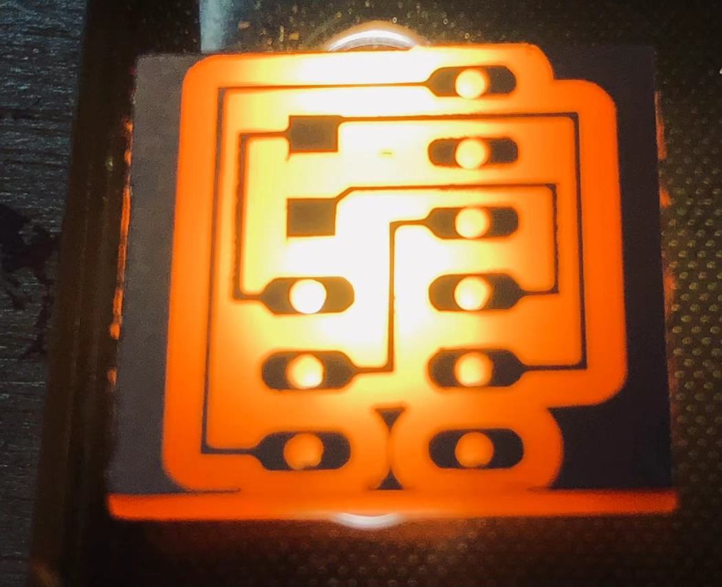
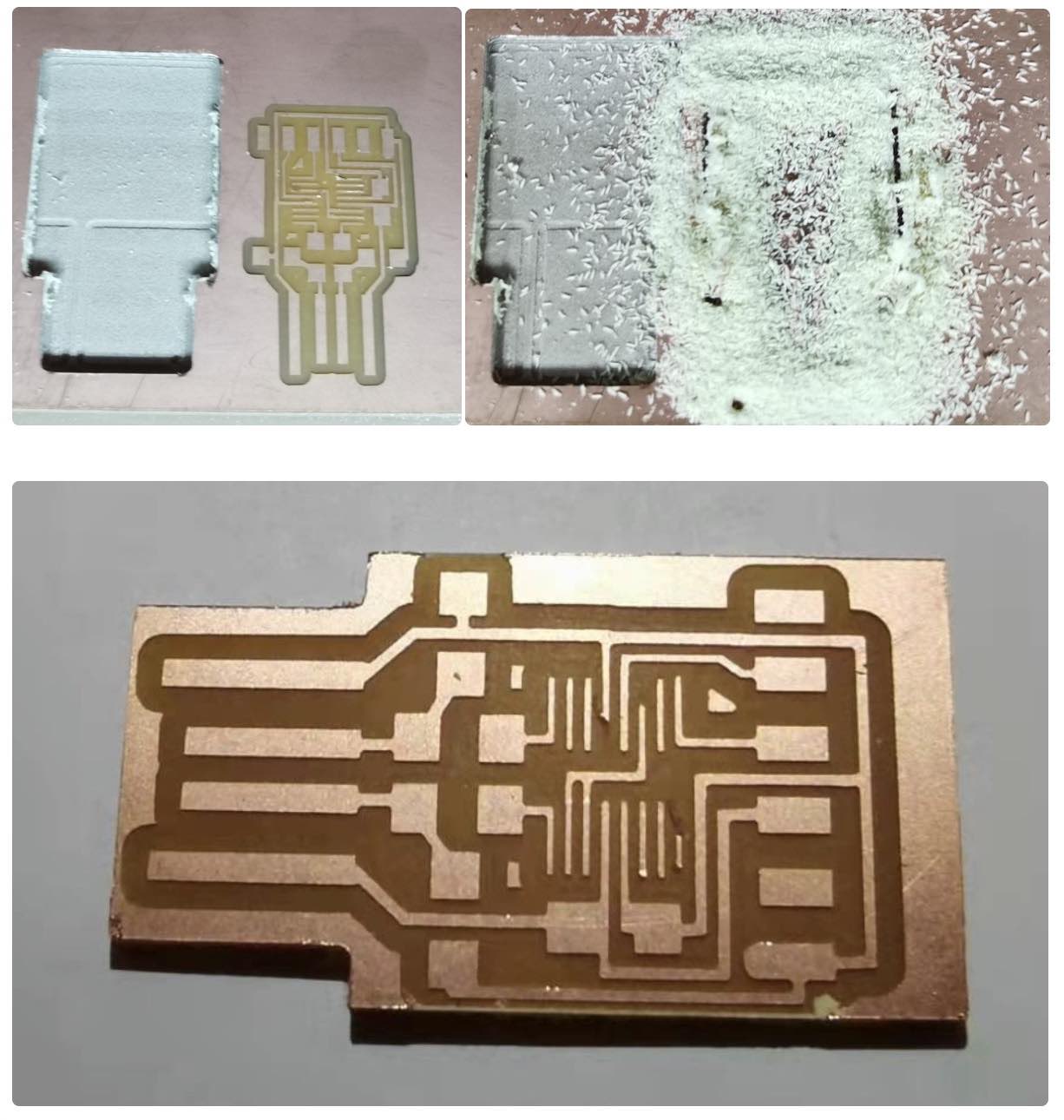
9 Hereo shoot
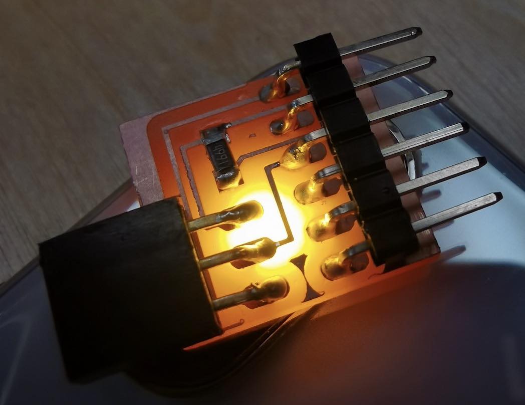
Here comes our board.
 We also did another test cut.
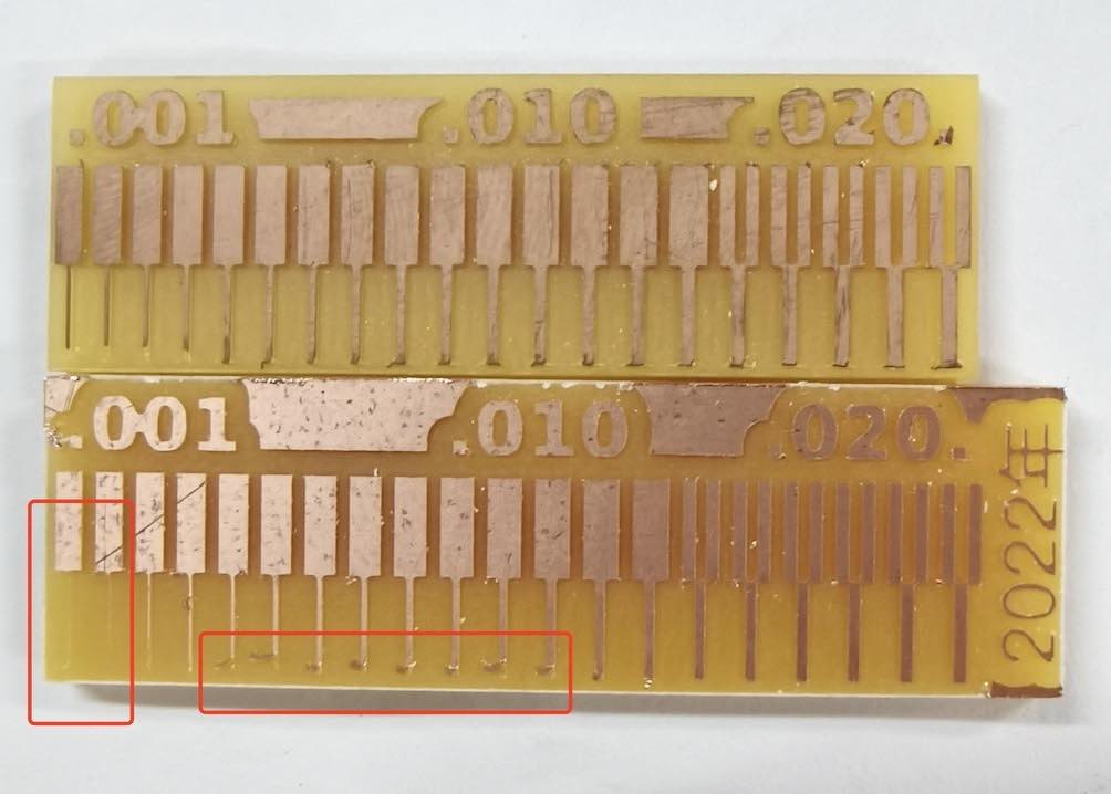 The first one was cut last year. The second one is ours. In our test the first two lines are not showing and line 5 to line 12 are partialy removed from the base board.
We used speed of 4mm/s,
Other Notes
End Mill
This is not the endmill we used. But this is good examples to understand the mesaurements.
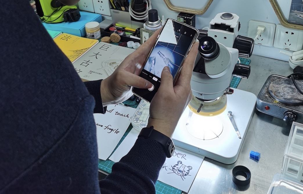
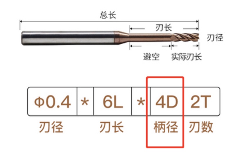 The top of end mill is very small and fragile. We used microscope to watch the detail structure.
Base
We used a chemical material brick. Some other student used wood as a base when cutting PCB.
TODO try add describe the picture by add title?
 Some others also used acrylic.
TODO say more about base
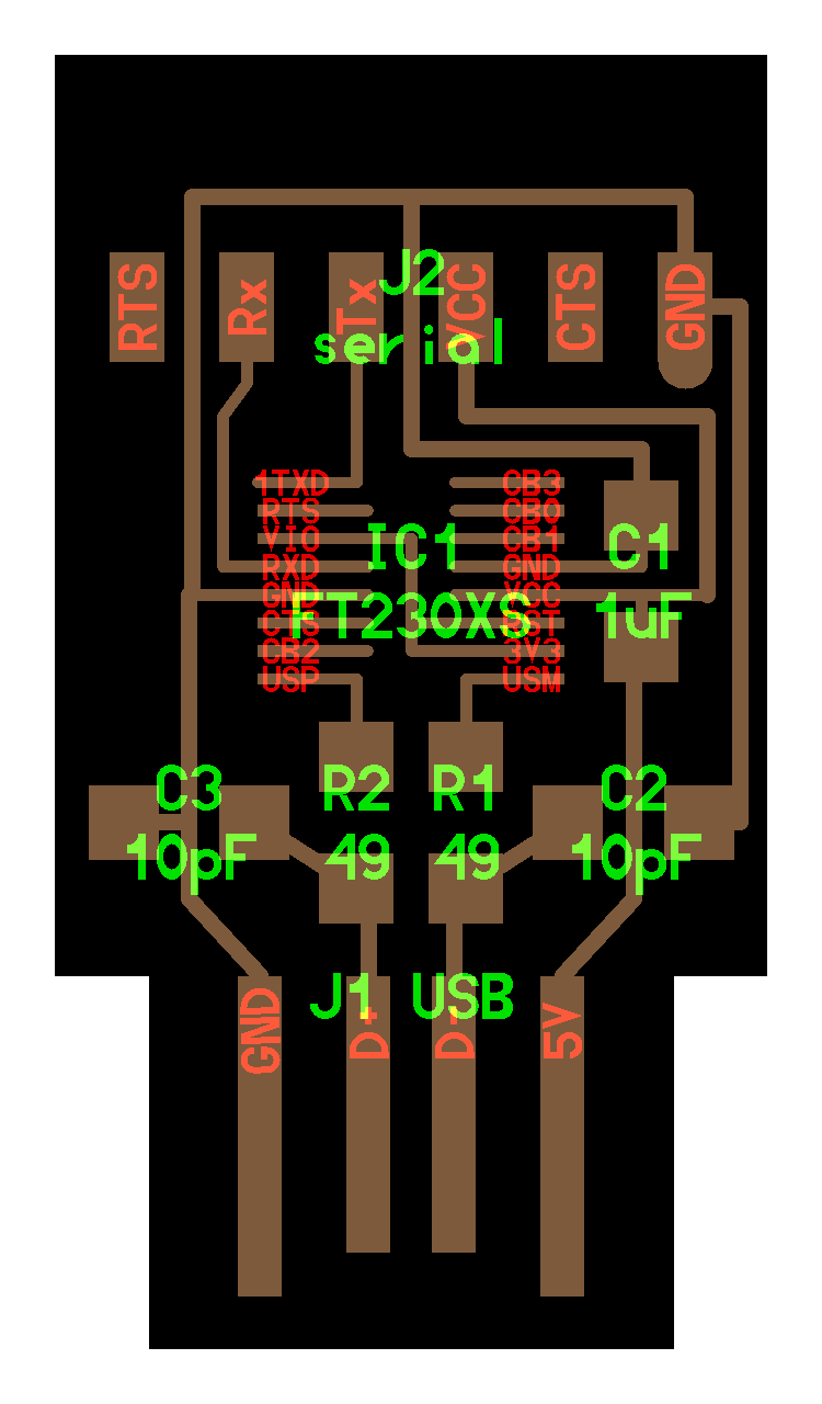
FTDI board
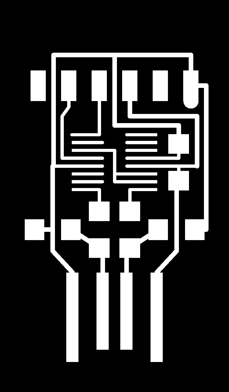
Follow the steps in first chapter, I cut the FTDI board.
TODO why we chose this FTDI
Source file
hello.USB-serial.FT230X board components traces interior
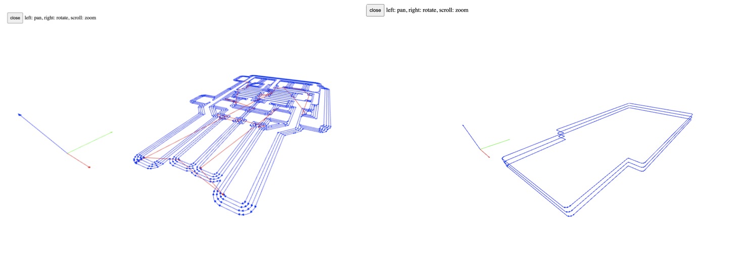
Generate rml files
 After generated files, check how the mill trace in three dimensional view.
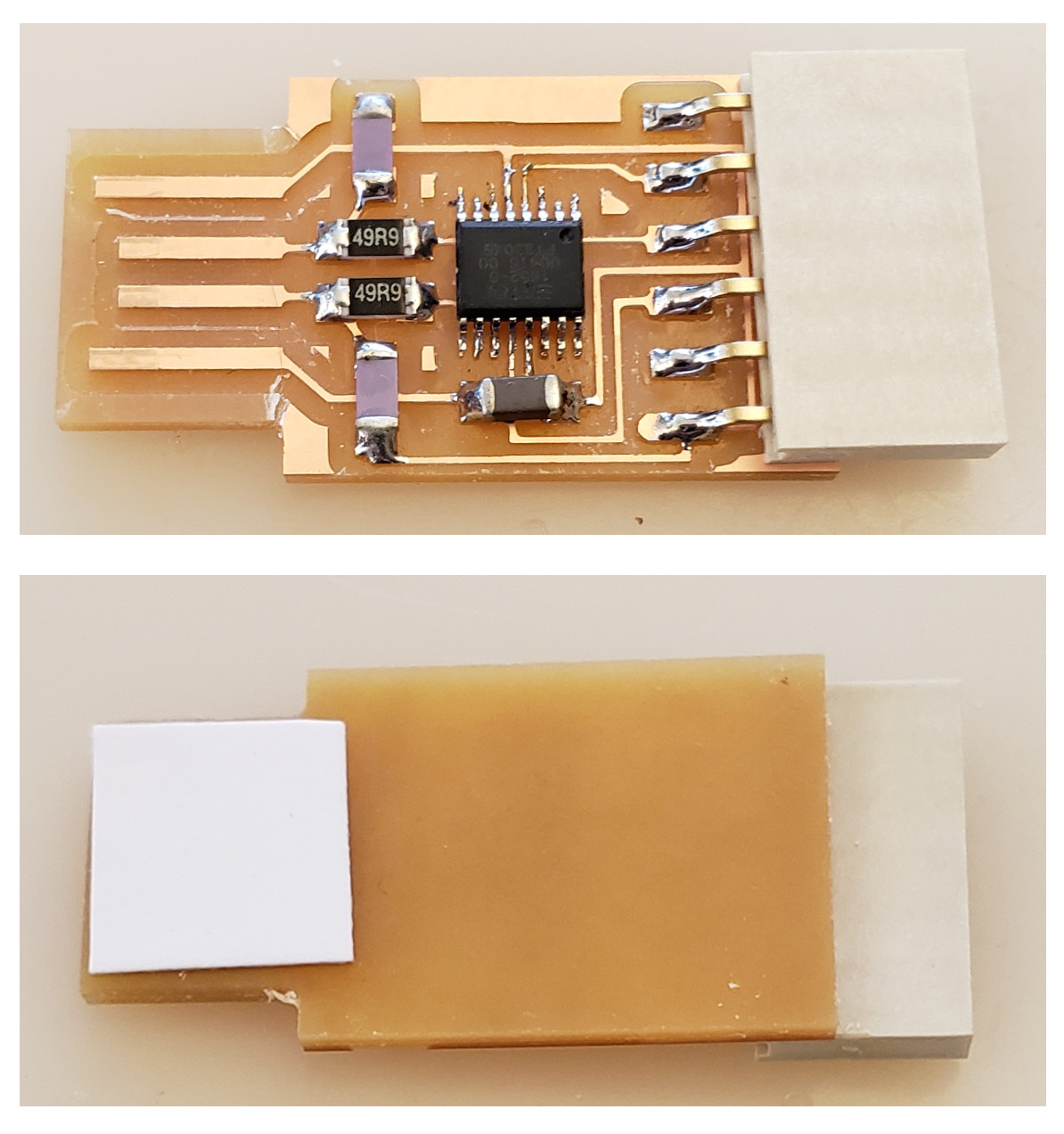
Cutting
Follow the safty rules and treat the end mill as they are precious goods.
Soldering UPDI board
Here comes the soldering part! I did soldering about 15 years ago.
The trick is…
- first iron in, wait, solder in. solder out, wait, iron out
- second iron in, wait, resistance in. iron out, wait, tweezer out
Always keep the iron and solder with 90 degrees, which goes better.