7. Electronics Design
Todo List
- Group assignment:
- Use the test equipment in your lab to observe the operation of a microcontroller circuit board (in minimum, check operating voltage on the board with multimeter or voltmeter and use oscilloscope to check noise of operating voltage and interpret a data signal)
- Document your work to the group work page and reflect on your individual page what you learned
- Individual assignment:
- Redraw one of the echo hello-world boards or something equivalent, add (at least) a button and LED (with current-limiting resistor) or equivalent input and output, check the design rules, make it, test it. Optionally, simulate its operation.
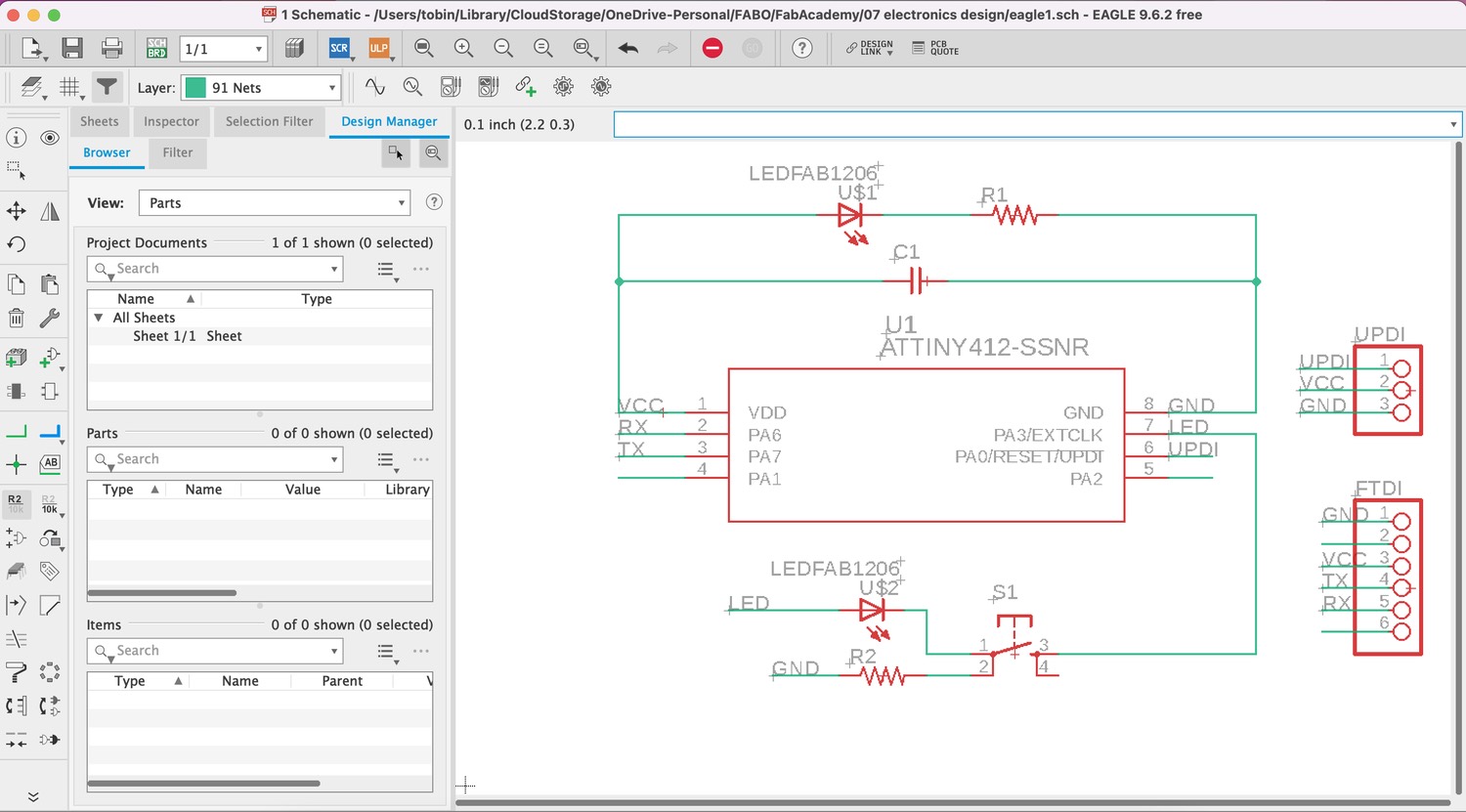
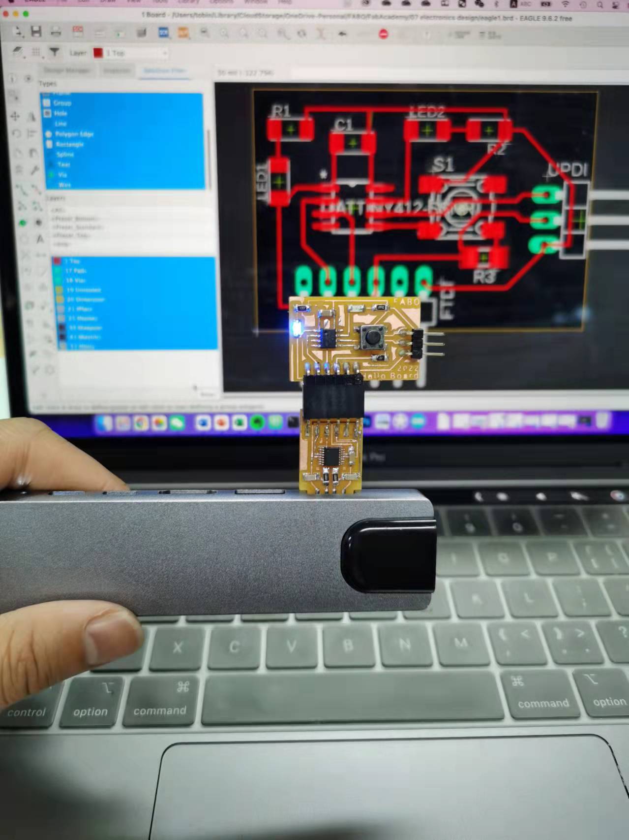
Design in Eagle
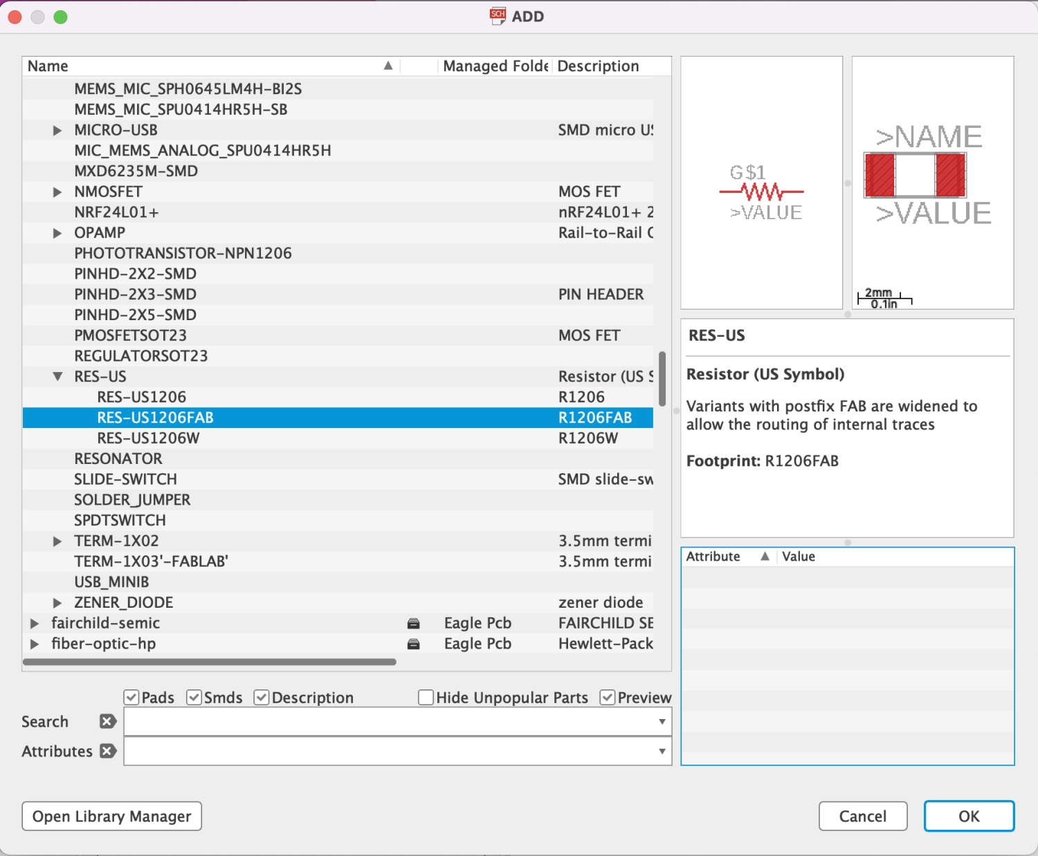
Compoments
Find the parts is tricky.
Compoment | Unit |
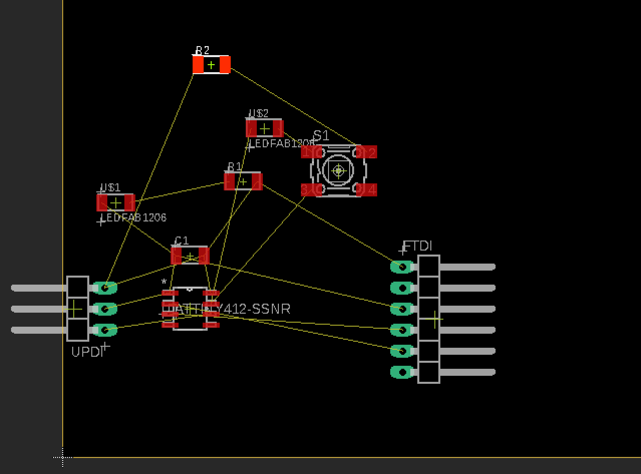
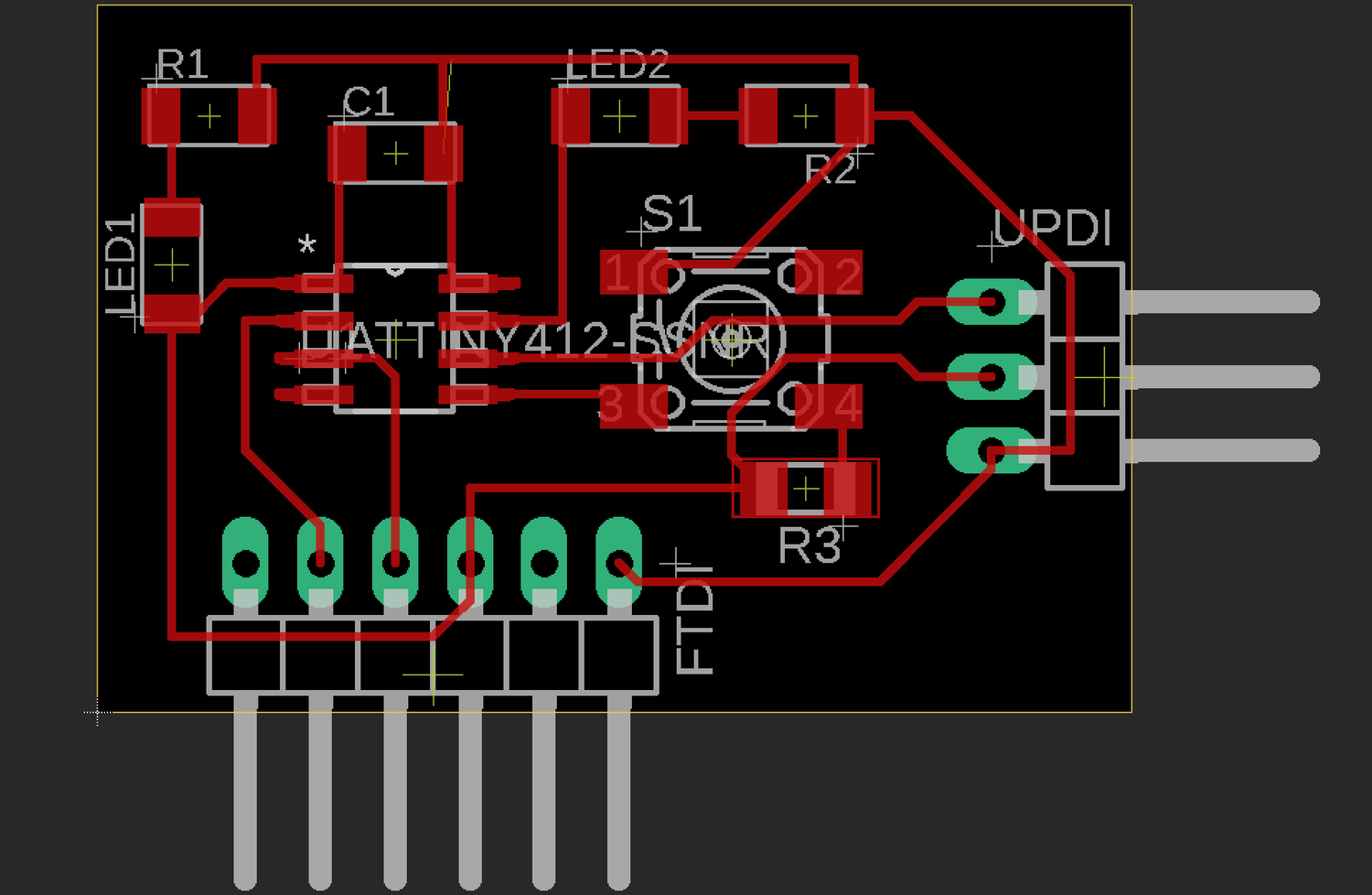
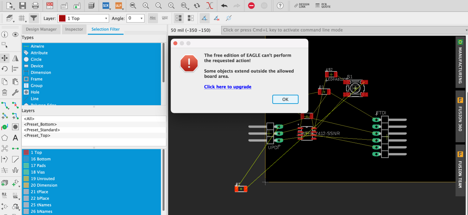
Design board
The pins to connect to ATtinyx12
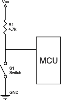
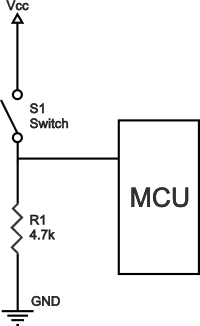
pull-up resistor
If there is nothing connected to the pin and your program reads the state of the pin, will it be high (pulled to VCC) or low (pulled to ground)? refer to: pull-up resistors1
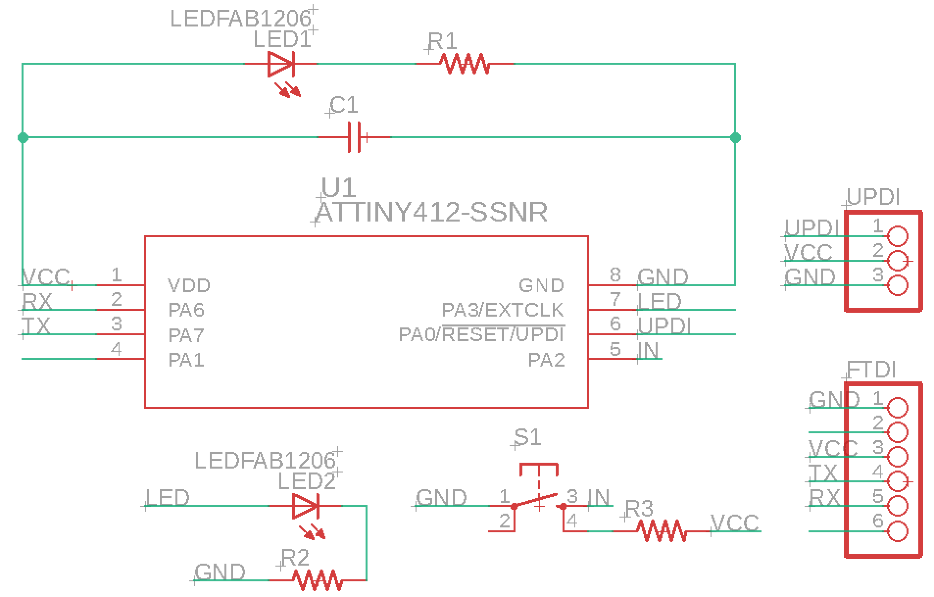
pull-up resistor pull-down resistor
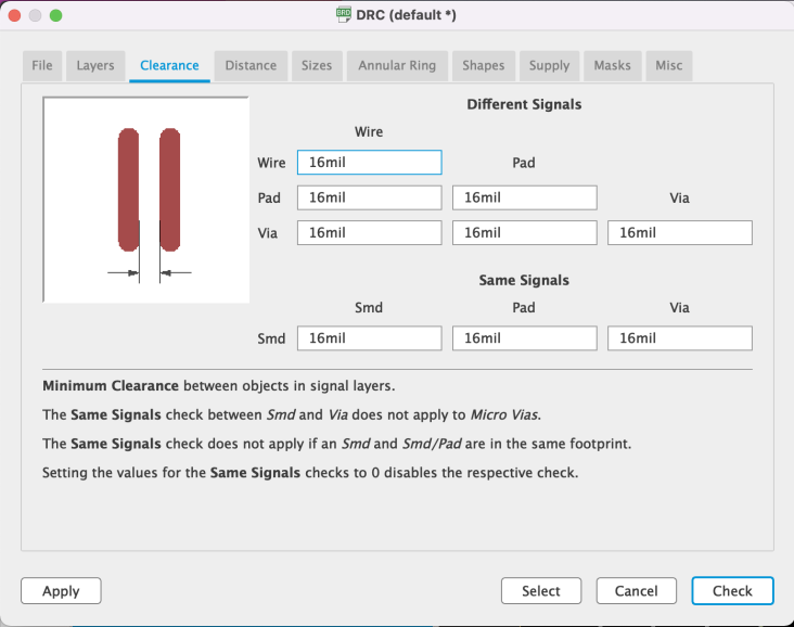
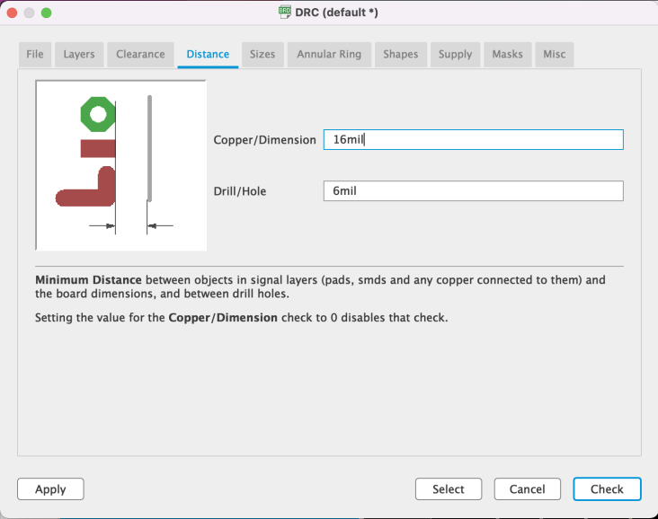
DRC
design rules check (in board view) - keep all the default settings (16 mil is fine); it should display a “no error” message in the bottom left hand corner of the screen
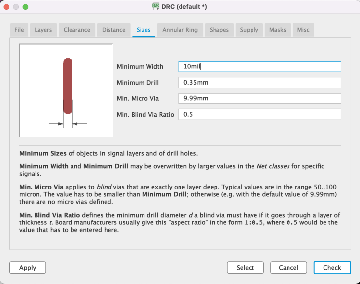
Without DRC

ERC
Electronic rules check; this ensures your board will actually work (use in schematic view).
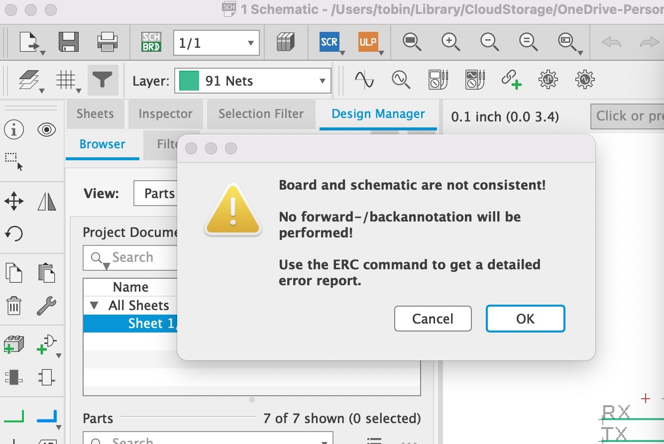
Not consistent https://community.element14.com/products/eagle/f/eagle-user-support-english/33051/board-and-schematic-are-not-consistent
How I solved it Rename one of the backup schematic file from the hidden backup.
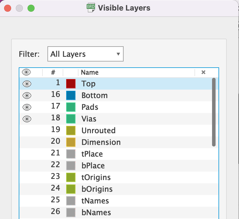
Layer Settings
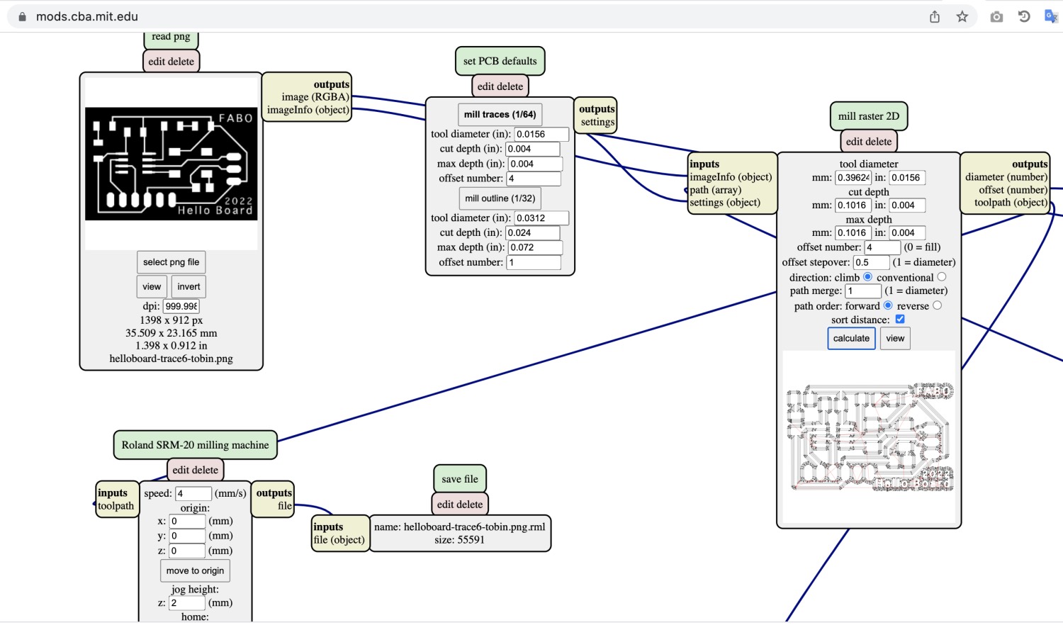
Export
Monochrome: checked. It is to make the output in gray color.
Resolution: 1000.
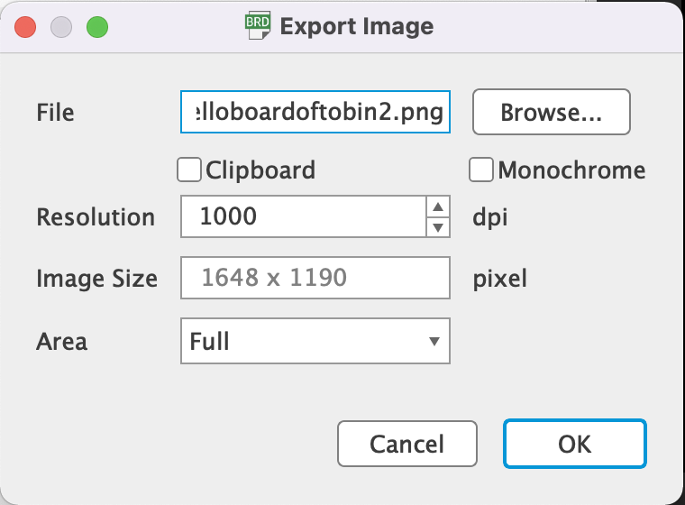
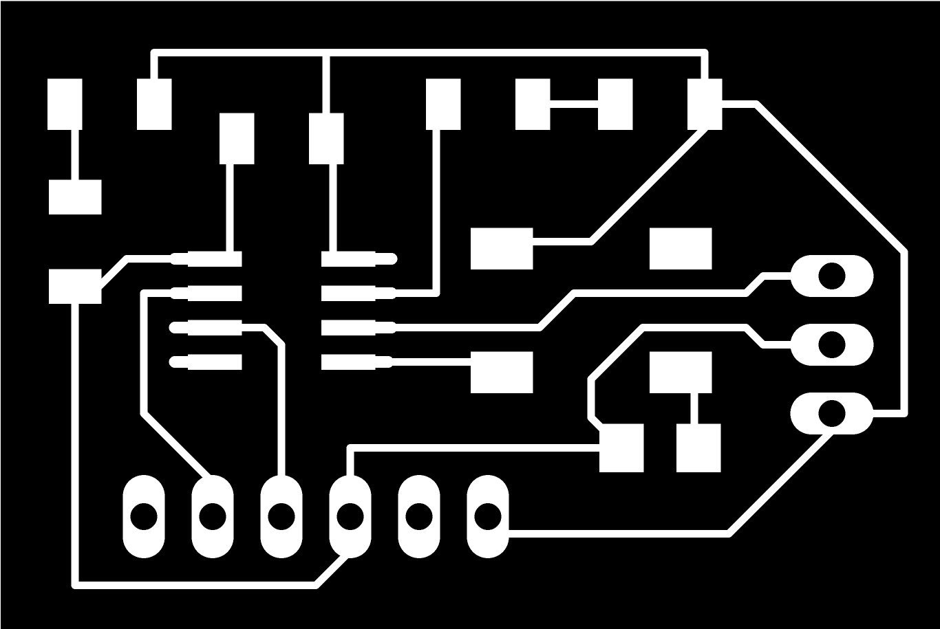
Issue
export a PNG image and the size become doubled. The issue is not fixed yet. Offical link: https://forums.autodesk.com/t5/eagle-forum/eagle-8-3-2-bug-on-macosx/td-p/7383581
Through Hole Guide: http://academany.fabcloud.io/fabacademy/2021/labs/kannai/site/instruction/tips/Eagle_Holes_making_shortcut/
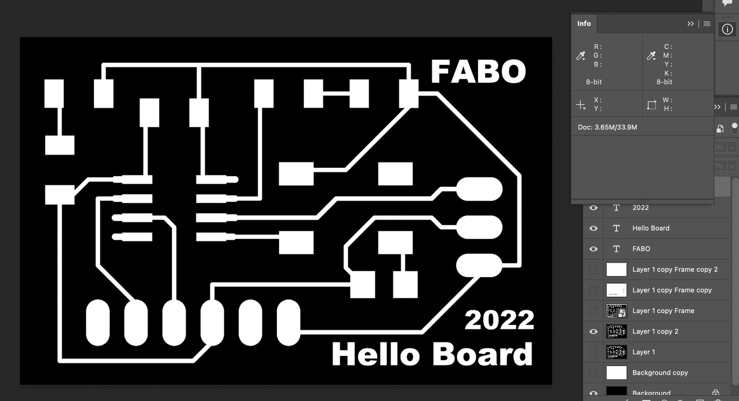
Modify in Photoshop
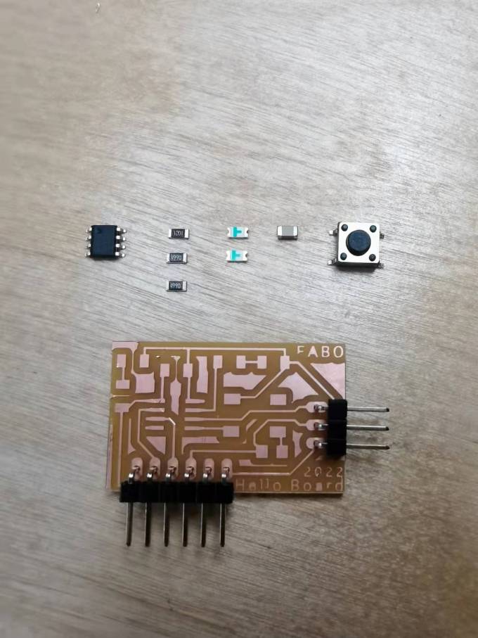
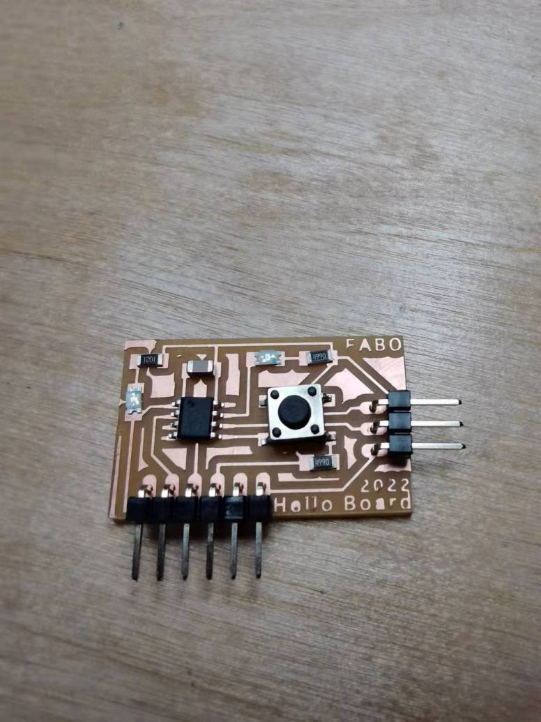
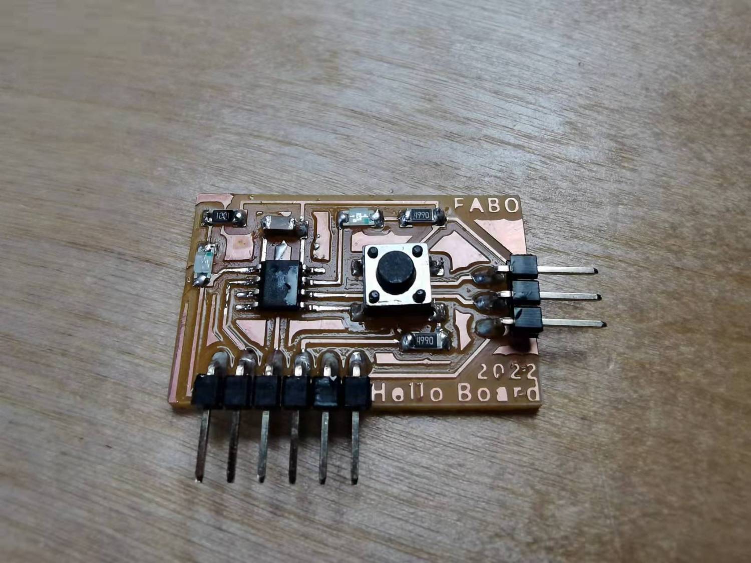
Soldering
Test it on computer, on this page it will not refresh automatically, so press Command+R to
refresh it.
Test in Arduino
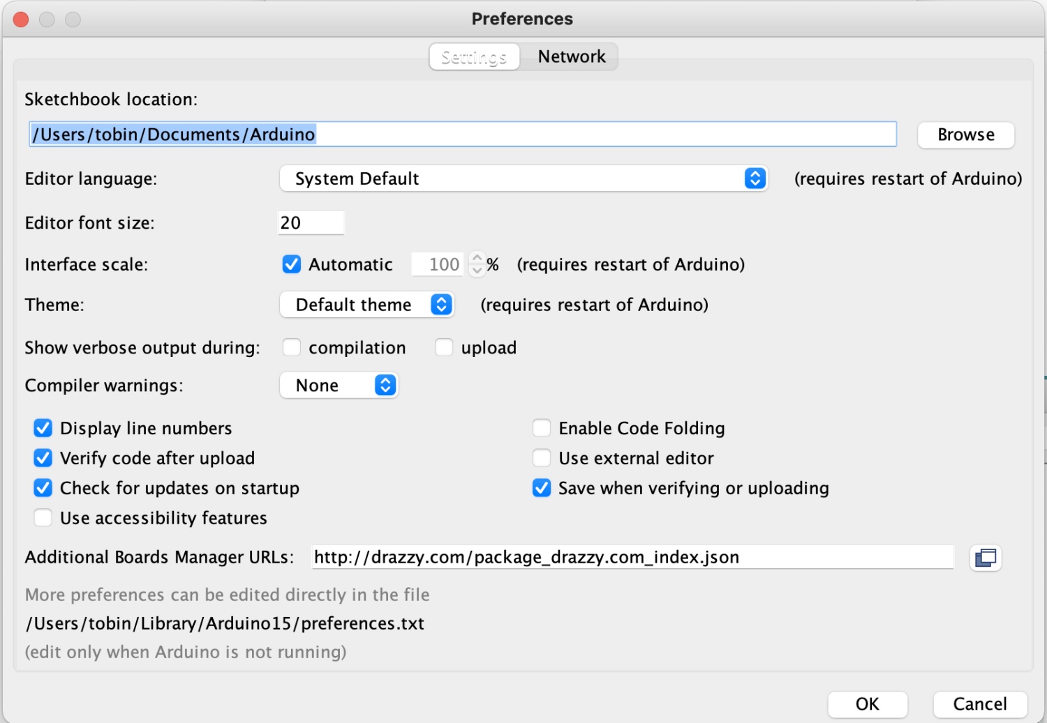
For this I use Arduino. Within Arduino, in the preferences tab we will add the URL to load the Arduino IDE with other cards or microcontrollers. Spence Konde tutorial.
The boards manager URL is: http://drazzy.com/package_drazzy.com_index.json
 Wait for the installation finish. It takes some time and also depends on the network. It failed several times when I do this.
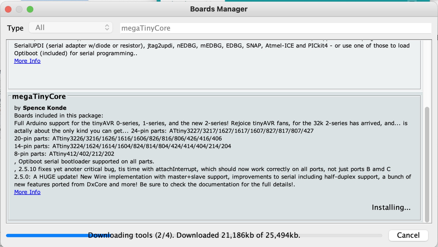
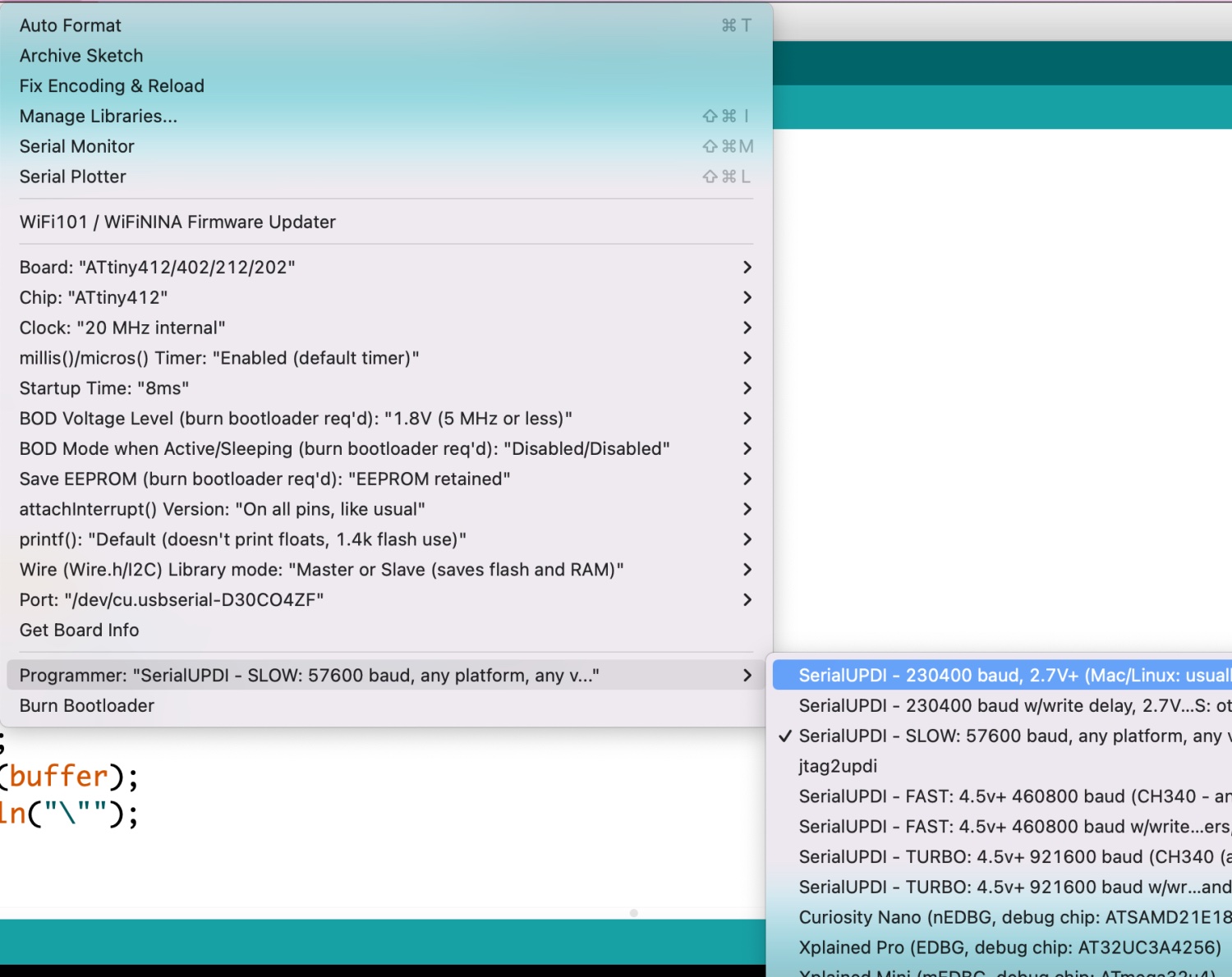
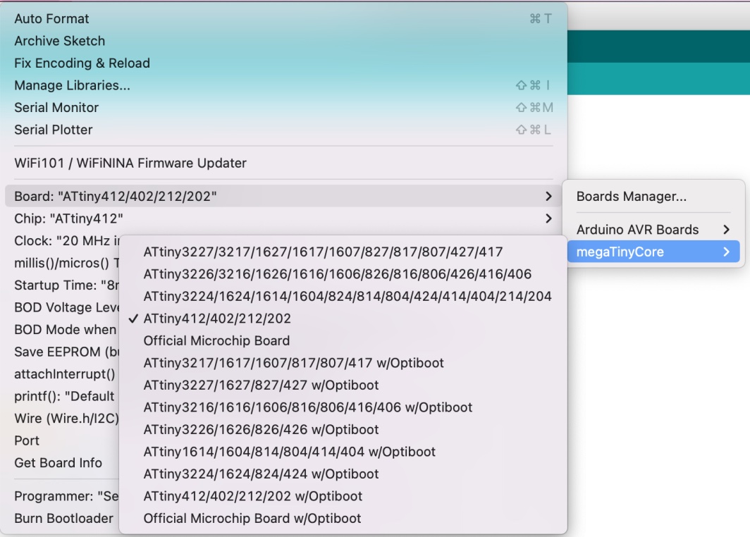
In Tools we select megeTinyCore>Board(ATiny412/402/212/202):
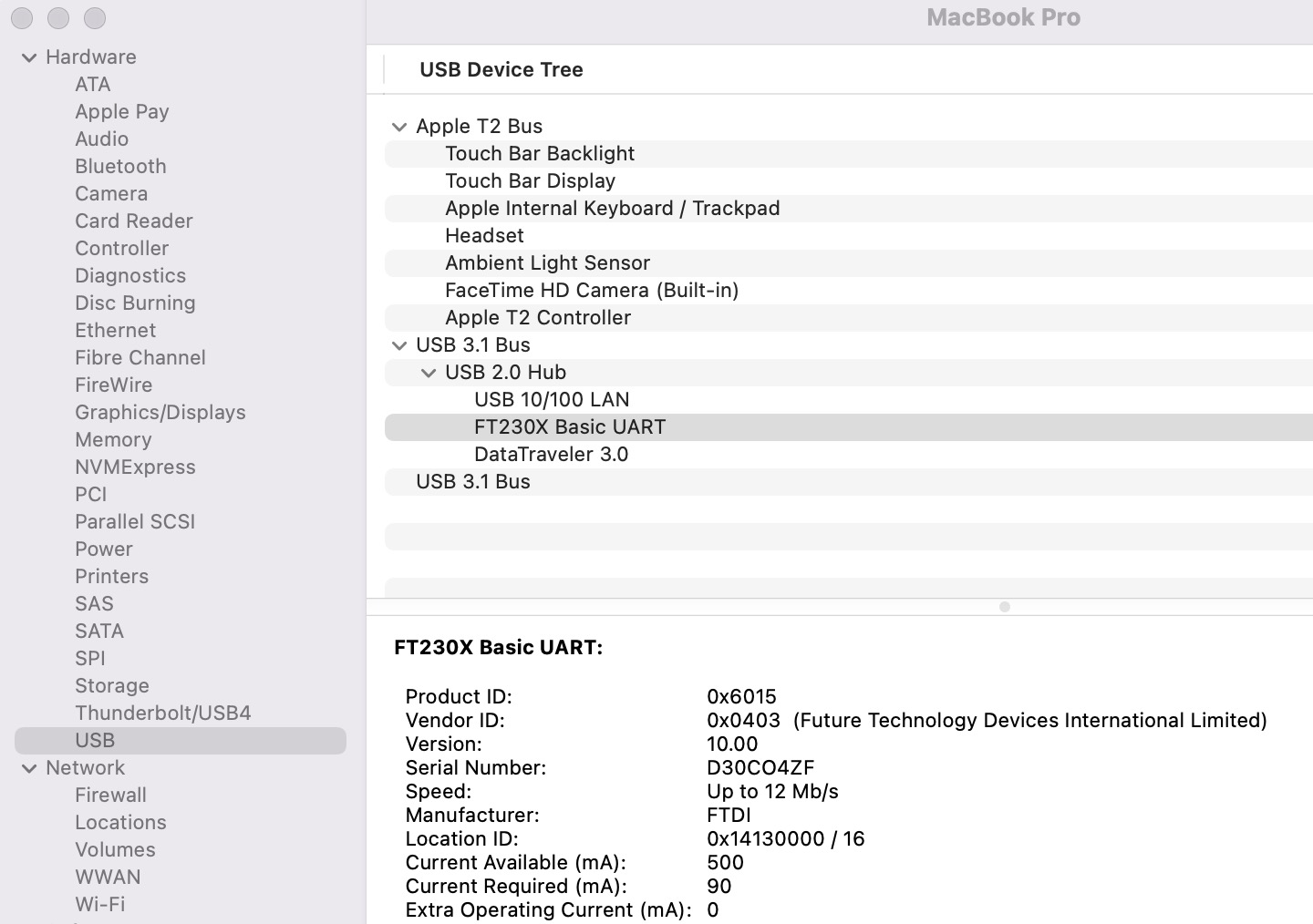
 Select the usbserial port:
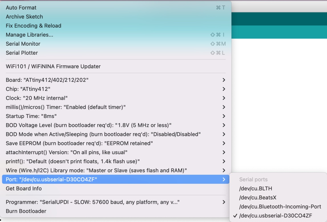 Select the programmer, I use SerialUPDI-SLOW: 57600 baud
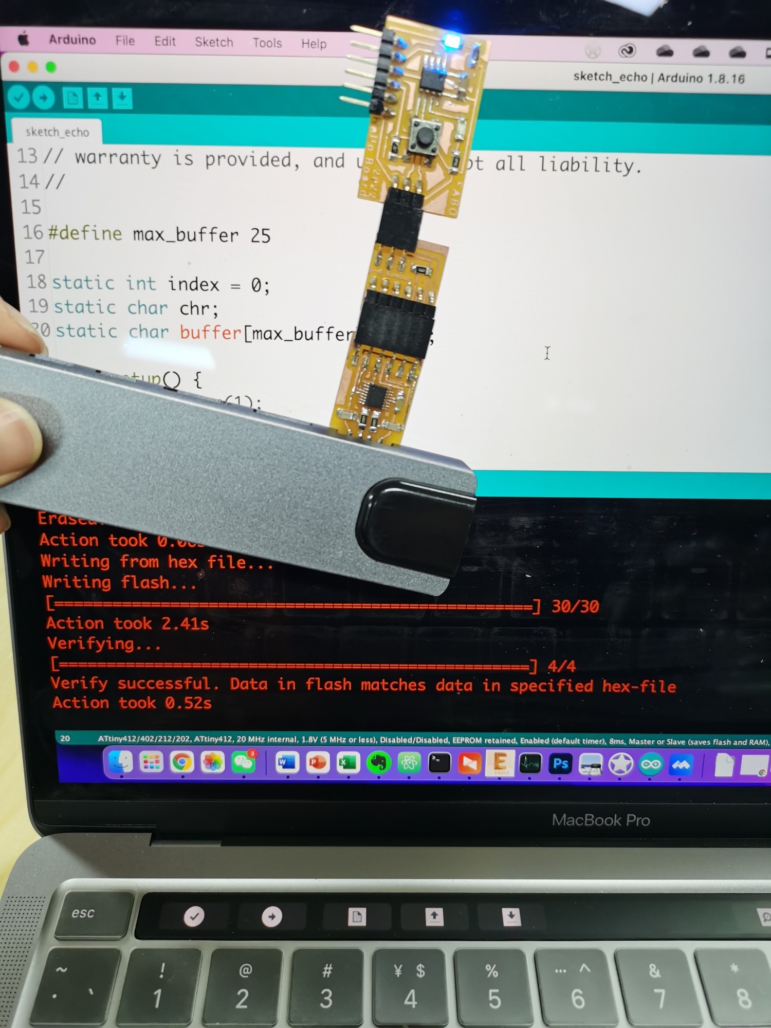
With the program from Niel:
//
// hello.t412.echo.ino
//
// tiny412 echo hello-world
// 115200 baud
//
// Neil Gershenfeld 12/8/19
//
// This work may be reproduced, modified, distributed,
// performed, and displayed for any purpose, but must
// acknowledge this project. Copyright is retained and
// must be preserved. The work is provided as is; no
// warranty is provided, and users accept all liability.
//
#define max_buffer 25
static int index = 0;
static char chr;
static char buffer[max_buffer] = {0};
void setup() {
//Serial.swap(1);
Serial.begin(115200);
}
void loop() {
if (Serial.available() > 0) {
chr = Serial.read();
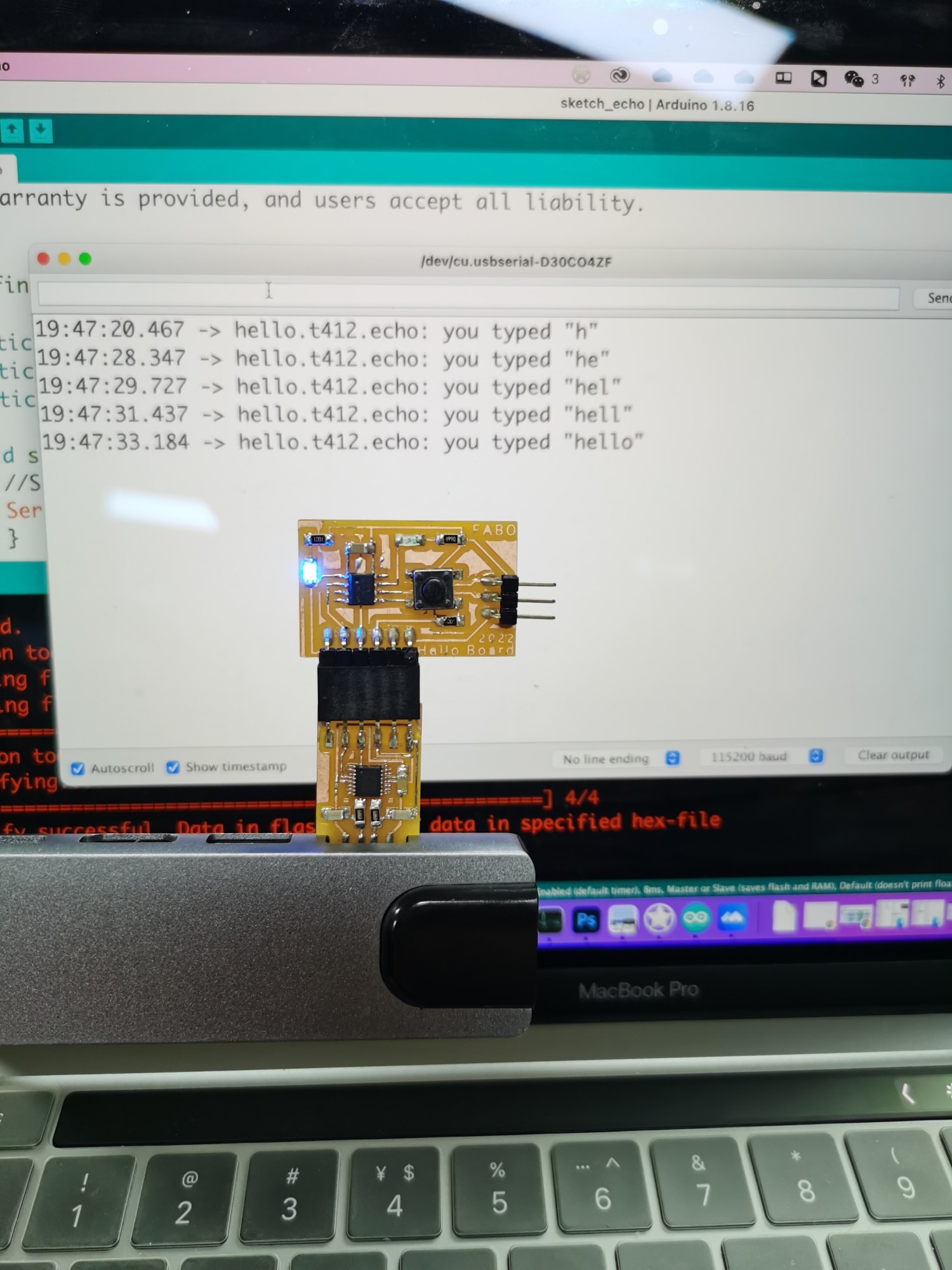
Serial.print("hello.t412.echo: you typed \"");
buffer[index++] = chr;
if (index == (max_buffer-1))
index = 0;
Serial.print(buffer);
Serial.println("\"");
}
}