3. Computer controlled cutting
This week I worked on testing the new lasercutter we have, designing for my press-fit kit, and using vinlycutter to make skicker for my students.
We met so many problems on this new lasercutter and handled some of them.
Here the following are what happened, how did we try to solve it, and what we are still working on …
DO NOT WASTE TIME ON MACHINE ITSELF
Group assignment:
- characterize your lasercutter’s focus, power, speed, rate, kerf, and joint clearance
- Document your work to the group work page and reflect on your individual page what you learned
Individual assignments
- Design, lasercut, and document a parametric press-fit construction kit, which can be assembled in multiple ways. Account for the lasercutter kerf.
- cut something on the vinylcutter
Todos
Learning outcomes
- [ ] Demonstrate and describe parametric 2D modelling processes
- [ ] Identify and explain processes involved in using the laser cutter.
- [ ] Develop, evaluate and construct the parametric construction kit
- [ ] Identify and explain processes involved in using the vinyl cutter.
Have you answered these questions?
- [ ] linked to the group assignment page
- [ ] Explained how you parametrically designed your files
- [ ] Documented how you made your press-fit kit
- [ ] Documented how you made your vinyl cutting
- [ ] Included your original design files
- [ ] Included your hero shots
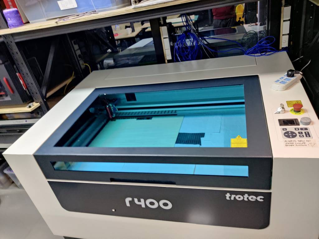
The lasercutter Trotec
We have a new lasercutter, named Rayjet, which is a sub-brand of Trotec, so we have to find out the right setting to cut and engrave.
This is the beginning of our nightmare.
Remember!
-
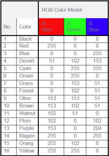
RGB mode: To specify what is a cut and what is going to be engraved, or to specify the different power and speed setting of different part, you must make sure the color mode of the file is RGB mode, and the RGB color value of each part corresponds to the colors in the software.
Here is the default RGB setting in the RayjetManager:
-
Line thickness: To specify what is a cut line, you must make sure the Line thickness of the cut line is 0.01mm. If the line is too thin to see in Illustrator, you can use outline mode to edit it with Ctrl+Y in Windows
-
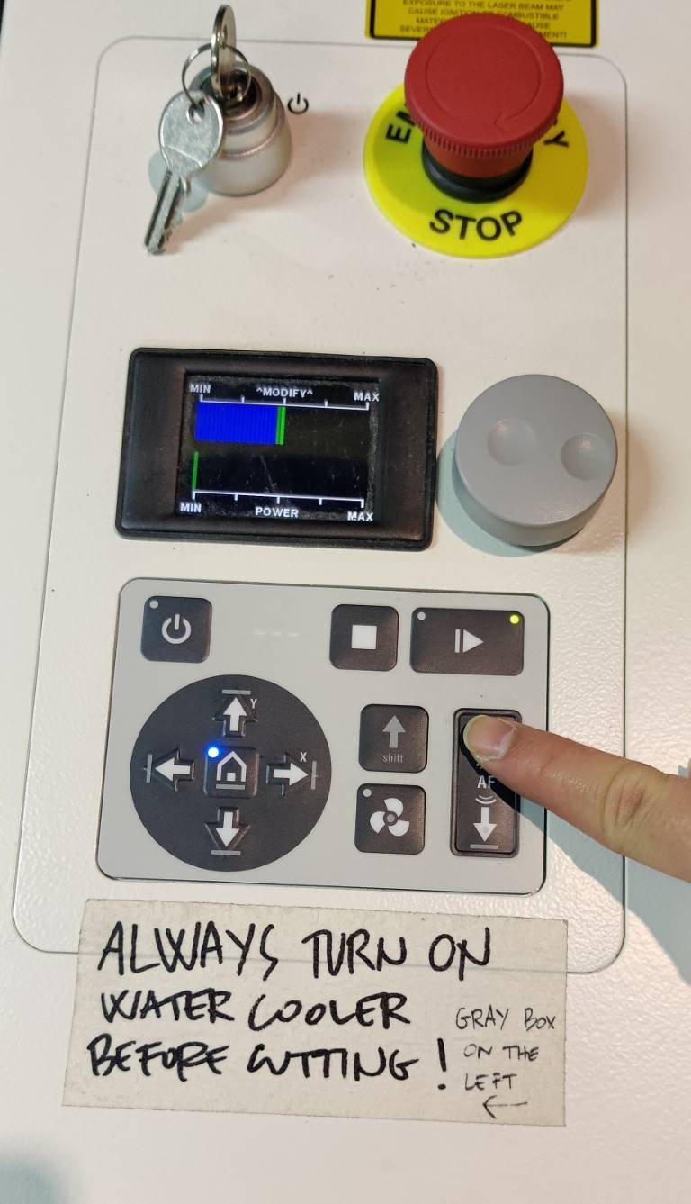
Turn on these machine: Before starting laser cutting, it is IMPORTANT to turn on these three machine: air compressor, Water chiller, air filter.
-
Wait before opening the lid: After the cutting is finished, don’t open the lid immediately, until the exhaust remove all the fumes.
-
Maintenance of the machine: It’s necessary to do the maintenance work for our lasercutter after using it. Clean the focus lens and the reflecing mirror, clean the waste bin…
NOTE THAT: If you don’t clean the lens, the stains, dust will adhere to the lens. When beam comes out, the lens will be heated, and then..break like this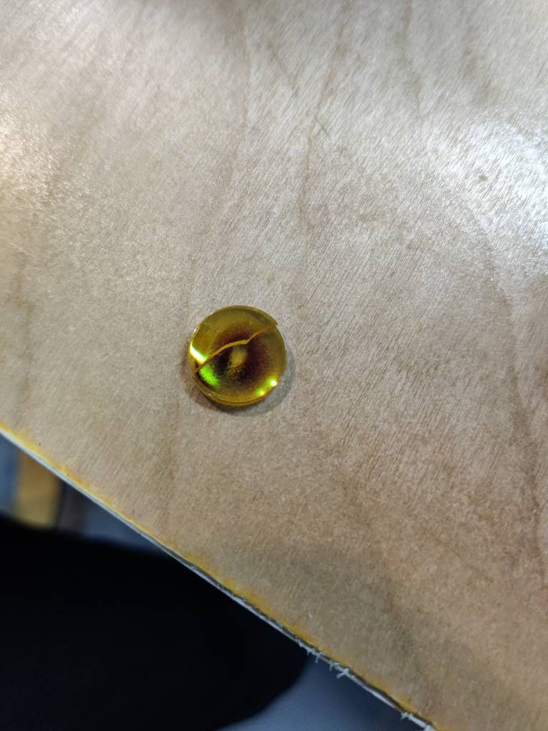
Characterize our lasercutter (G.A.)
(Group work With @Tobin)
What kind of lasercutter it is?
Trotec is a CO2 lasercutter.
What kind of material we will use?
We will use 3mm plywood board to test and learn to use it.
What software we will use?
We will use Adobe Illustrator and Fusion 360 to draw some simple shape to test,
and use RayjetManager to control this naughty machine.
A. Focus
- Put the material on the cutting surface.
- After powering on, the cutting surface will go down.
- Hang the focus regulator on the head
- Move the head to where you cut, and move up the surface slowly, until the regulator touchs material surface and falls down.
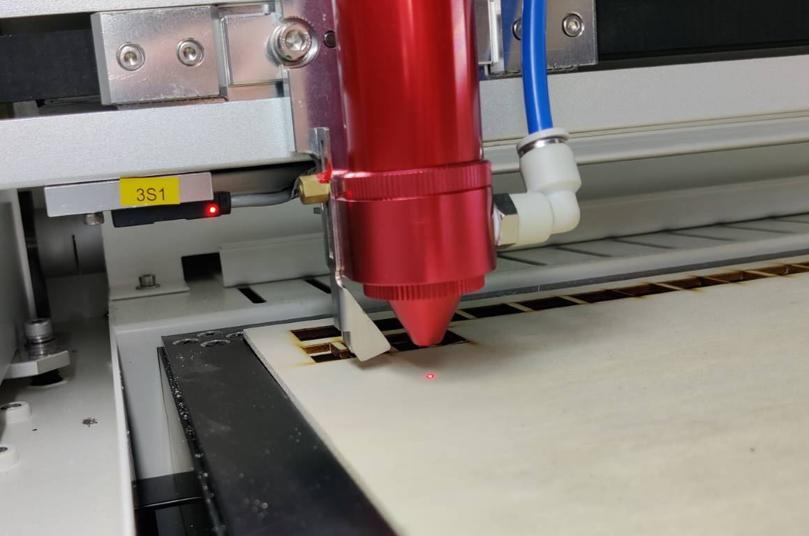
- Focus complete!
B. Characterise!
What need to be characterised?

-
Power: basically the power is how much power the laser beam outputs. Every machine and every material will vary on this, but you must set the power percentage either for cut, engrave or vector scoring every time.
-
Speed: this speed is how fast the laser head travels. Again every machine and every material will vary on this, normally engraving (raster) has to be much more faster than a cut.
-
PPI: PPI stands for “pulses per inch”, also refered to the frequency, this is the pulse rate per linear inch of travel. Default in 500 when engraving is Ok.
-
Correction: This is the most strange setting need to be tested. In the mannul of ReyjetManager, Correciton is describe as this.
Determines the minimum percentage of laser power of the selected laser power which is set during slow movement; for example around curves in vector mode or acceleration phase during engraving mode.
Vector mode: If the setting of this value is too small, the lines will thin at the ends and in the radius or disappear completely. If the selected correction is too high, the width will strongly increase at the line ends and radius.
Engraving mode: If the setting of this value is too small, the borders of the engraved image disappear or get less ablated because of material or laser nonlinearity.We tested so many times to find out which correction is correct to our cut and engrave setting, but it still a long way to go.
 In short, maybe it is useful to customize Correction, but we still need an auto-configuration switch to keep our simple laser work simple. See more about it, go to Strange things happened part
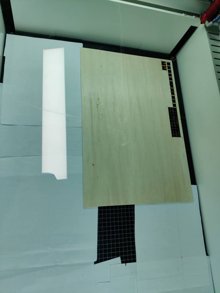
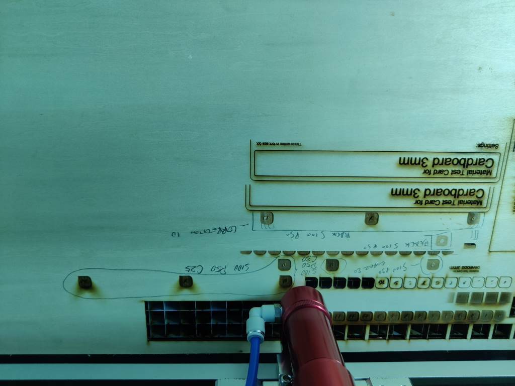
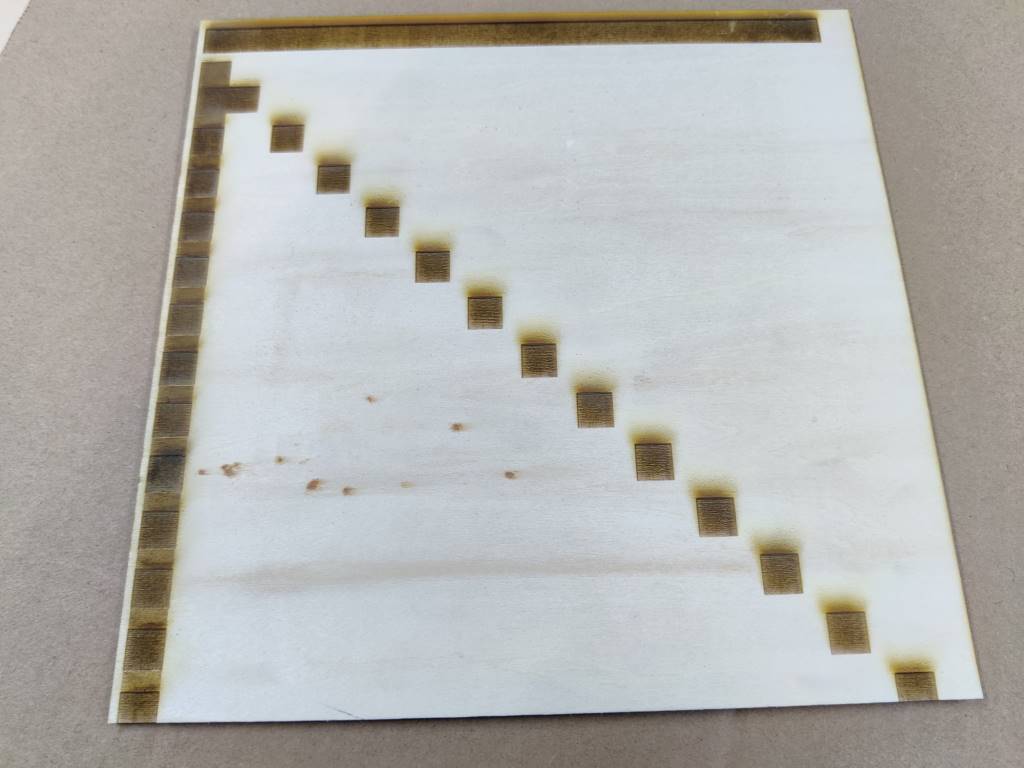
Start test
- Draw a test file in Illustrator. (The length and width of each figure are 10mm)

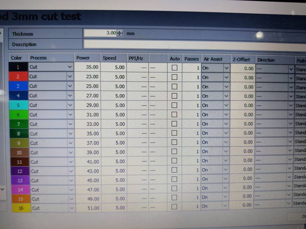
- Give every color different setting. (Adjust the power when speed is fixed)
- Measure the thickness of the plywood we have with a vernier caliper from different direction. We got 2.95mm, 3mm, 2.98mm, 3mm. Nice!
- Start cutting and we got this.
Edge of the No.7 is best, so power 35% and speed 5% is the a setting to cut 3mm plywood. (But why the number is not continuous, it’s the Correction issue)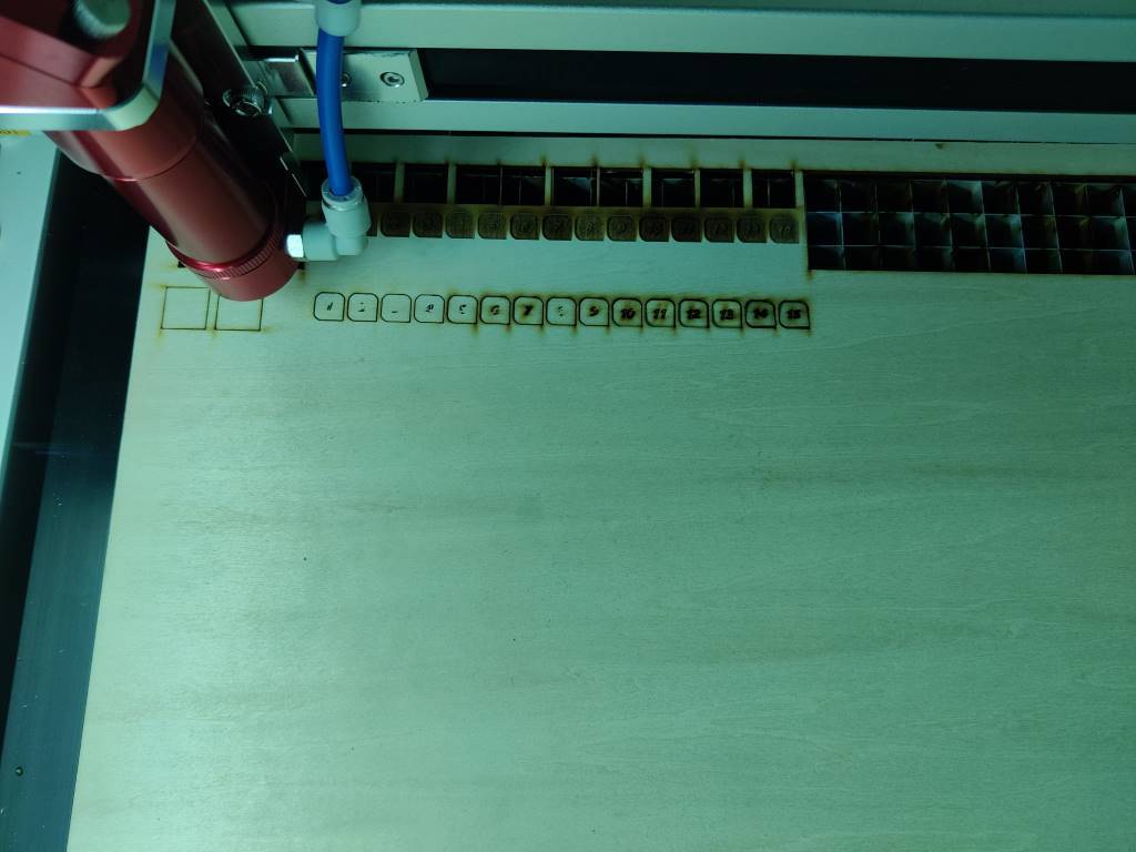
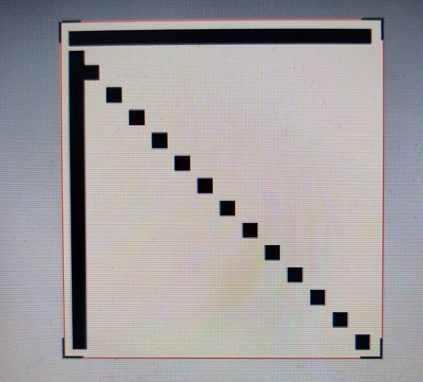
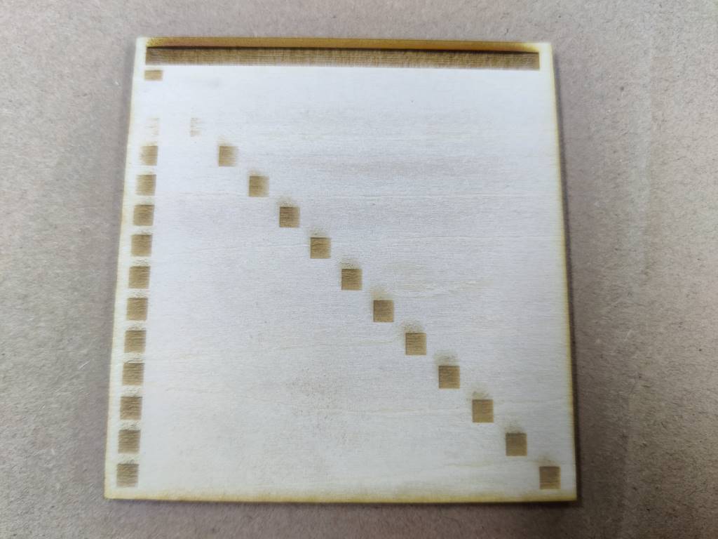
C. Kerf test
- Draw 10 squares in Illustrator. (The length and width of each square are 10mm) And make sure you don’t have lines overlaped. (Screen shot in outline mode, so you can see some point in the center of the sqare)
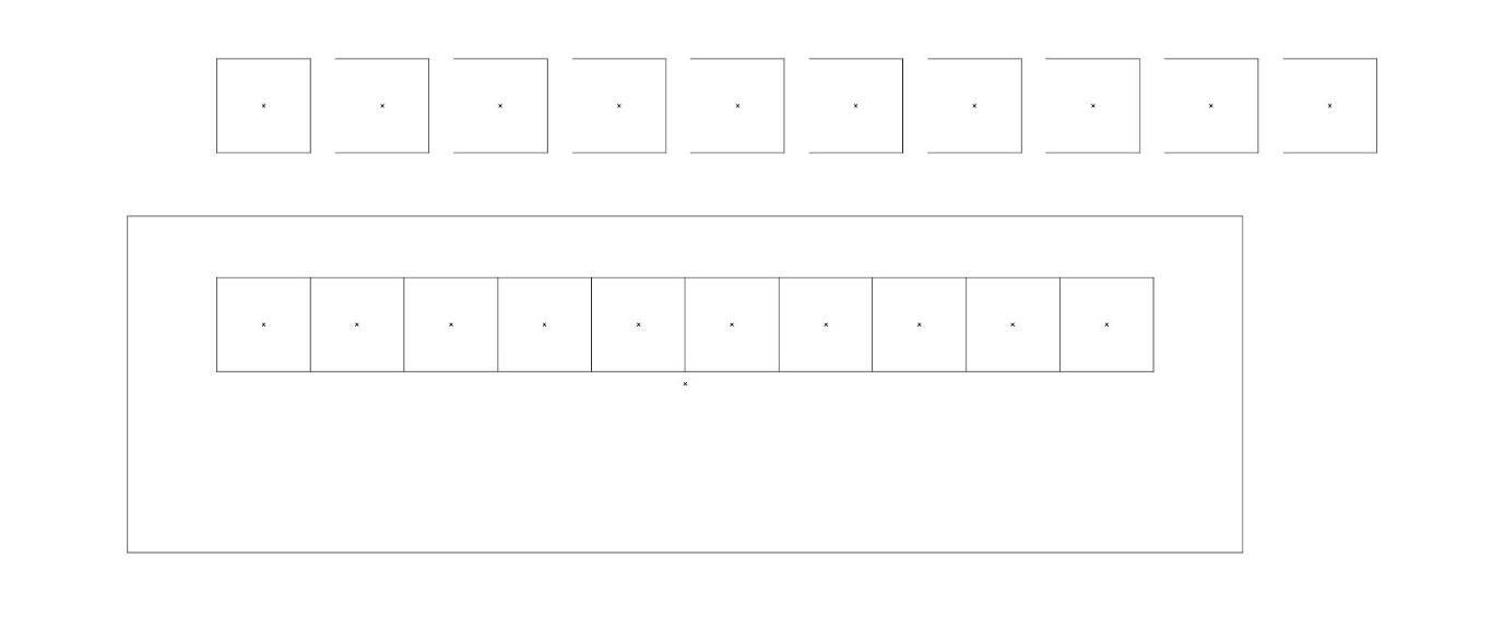
-
Use the setting we test before to cut this file. It will have 11 gaps.
-
Take the squares out and put them back, we can get a big gap which is equal to 11 times kerfs
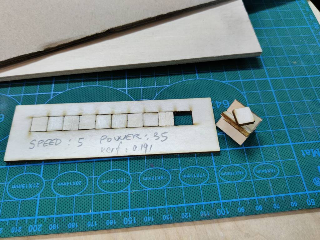
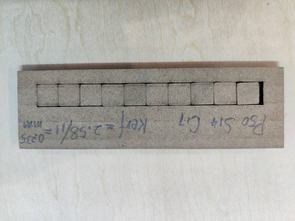
-
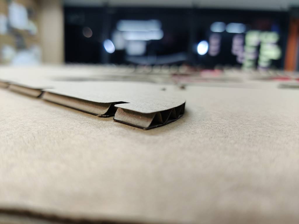
We also test the kerf of cardboard
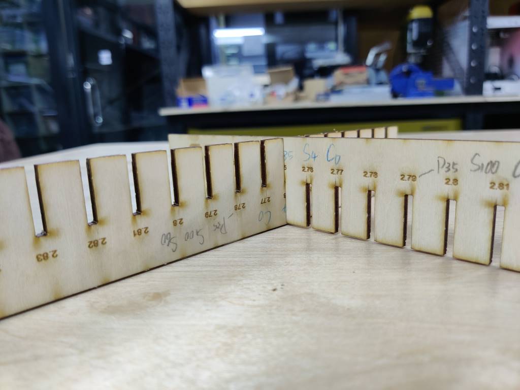
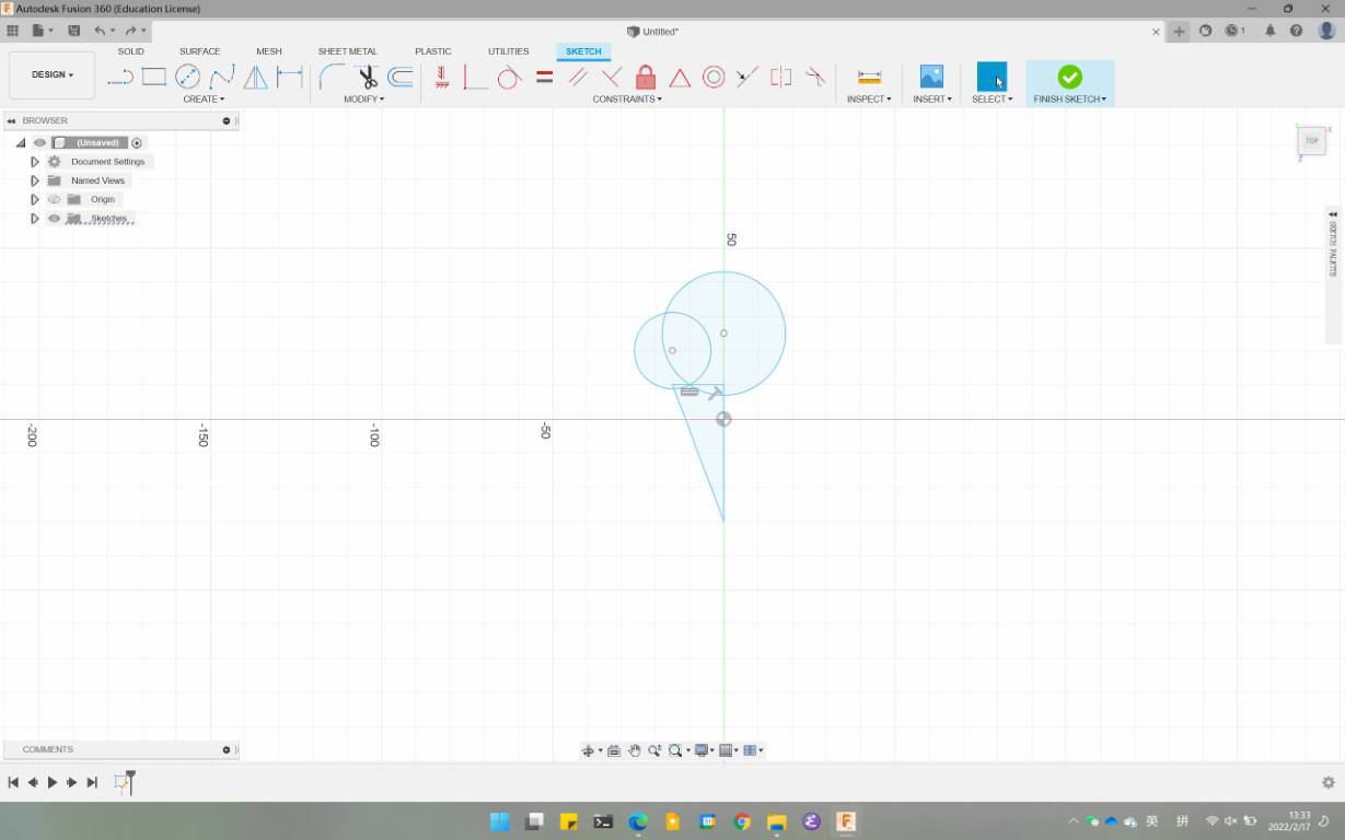
D. Joint test
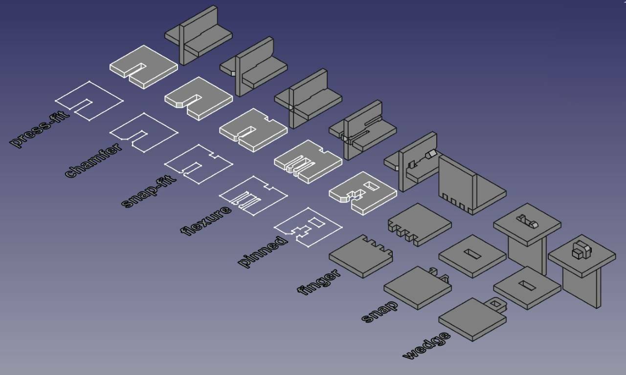 1. Draw a square with a gap.
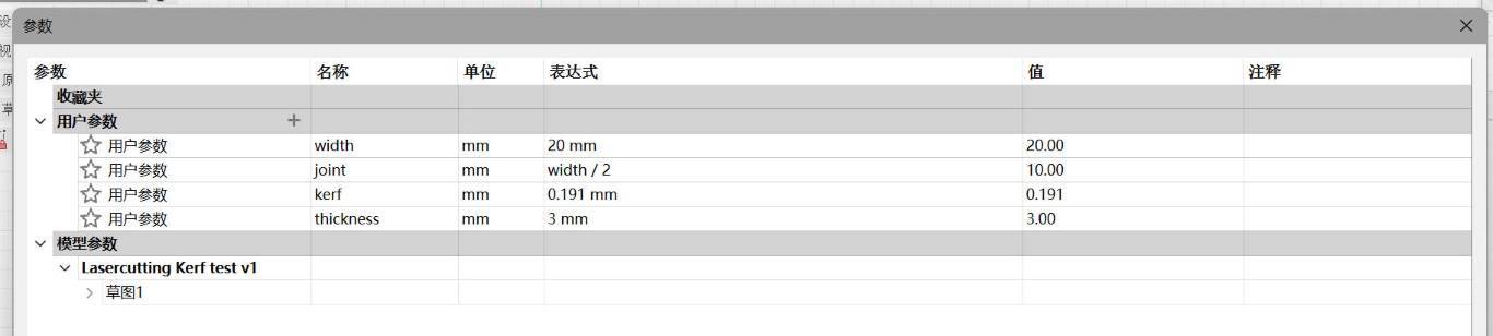
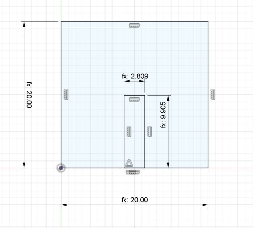 2. Set Parameter like this.
 3. Save the project as .dxf, and import it to Illustrator, adjust lines and make sure the length of each line are correct. And cut it
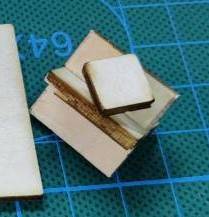
4. And we get this.
3. Save the project as .dxf, and import it to Illustrator, adjust lines and make sure the length of each line are correct. And cut it
4. And we get this.
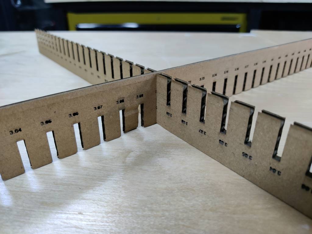
- we also use the Kerf Check tool shared by Rico, to test more detailed.
The gap of our 3mm plywood board from 2.70mm to 2.75mm works well, and 3.70mm gap is the best for our 4mm cardboard.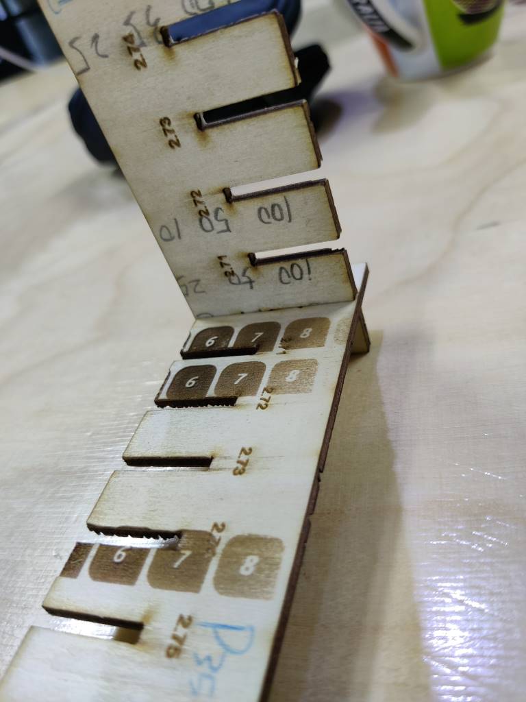
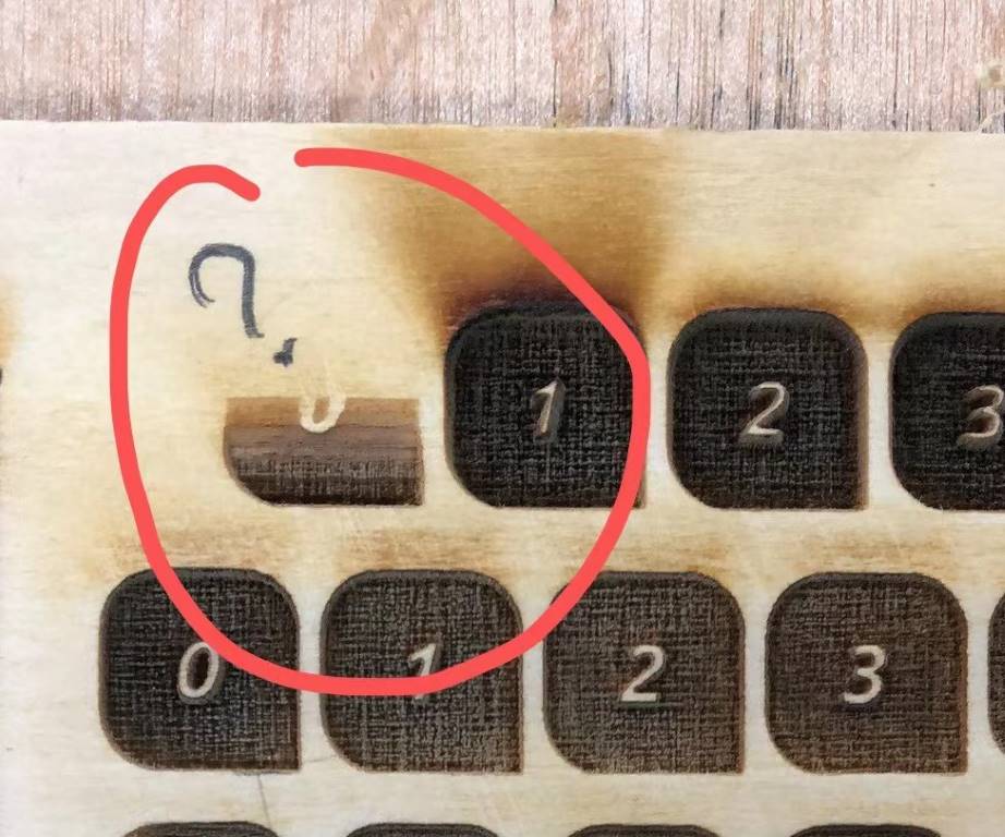
E. Engrave setting test
F. Strange things happened
The Correction issue
the most strange thing
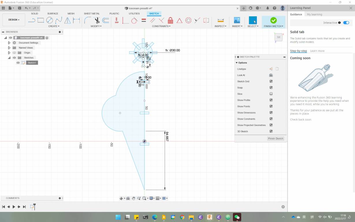
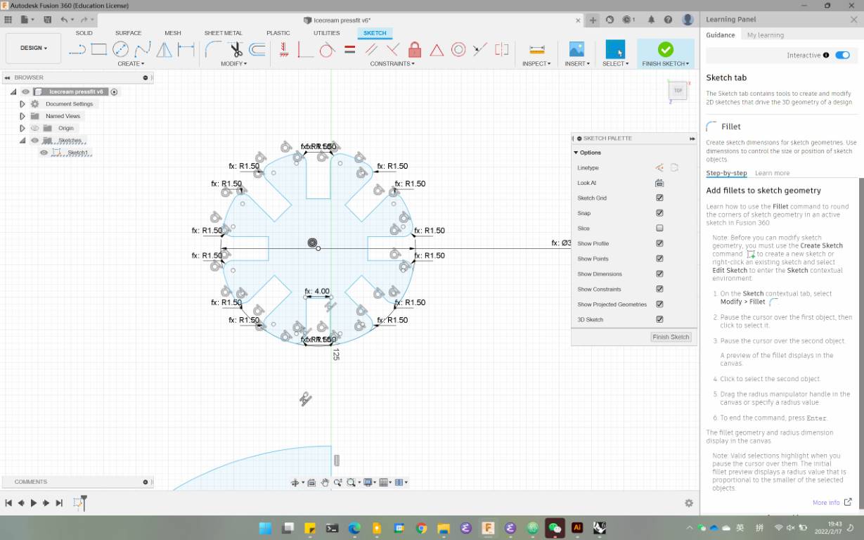
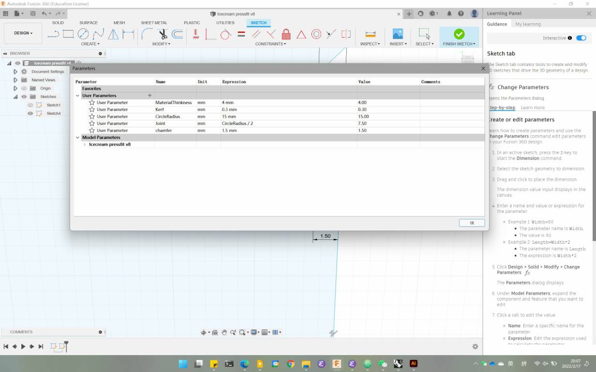
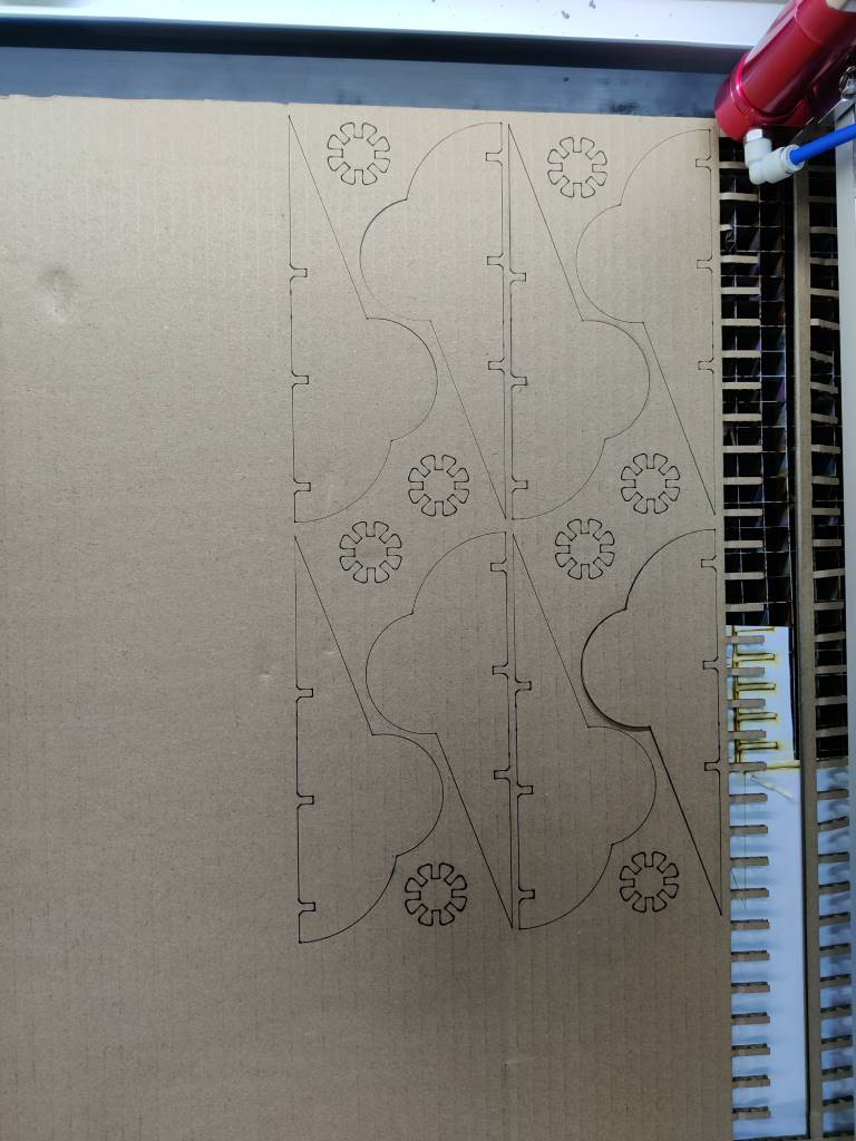
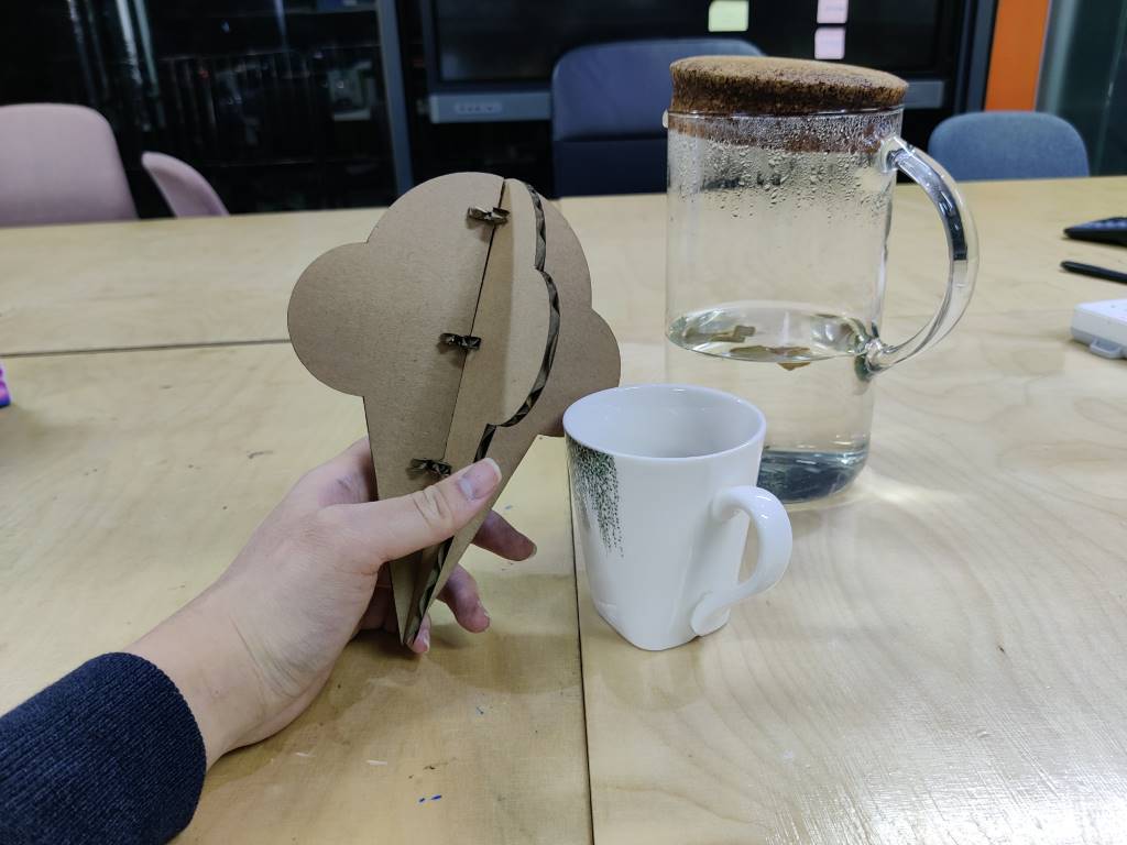
Parametric press-fit kit
Vinyl cutter
- After you load the material, you have to select if it is a ROLL or a SHEET.
- Select the force value. This will depend on the material sheet grammage.
- The position where you locate the vectors will affect where the machine will cut, so the preview you see on the artboard of the software is actually the place where the machine will cut it.
- You have to make sure each line of your design is less than 1mm;
- And save the file as Illustrator 3, or the CutStudio will not open the