6. Electronics Design
This week I designed my own board and program it!
Test & Observe (G.A.)
(Group Assignment with @Tobin) More about our groupwork, plz go to Tobin’s w6
Make My Own Board!
I’ve learned basic electronics, so this part is not hard for me.
Design my board
-
EAGLE! We choose this education free software to design our borad. Learn more about how to design a board with EAGLE, you can go to Fab Academy Tutorial

-
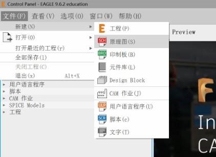
File -> New -> Schematicto start a new design
-
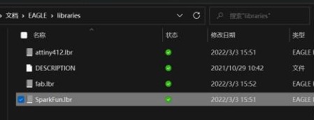
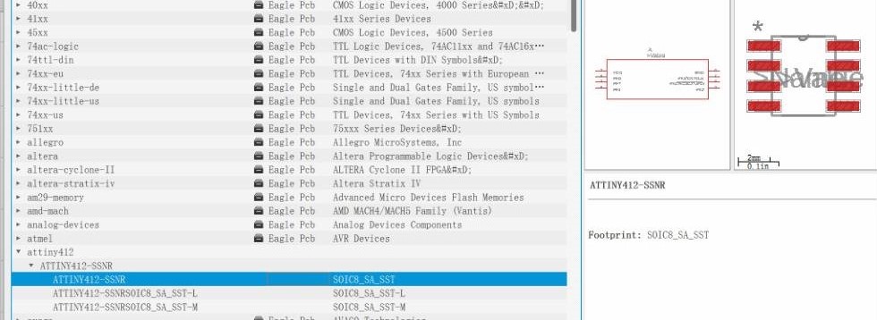
Download attiny412 lib, fab lib, sparkfun lib from Saverio. Also in the Fab Academy Tutorial
-
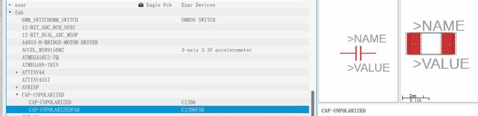
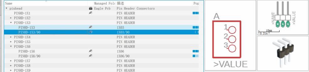
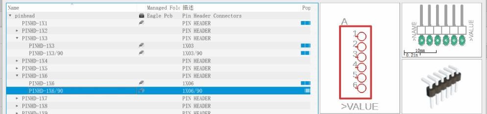
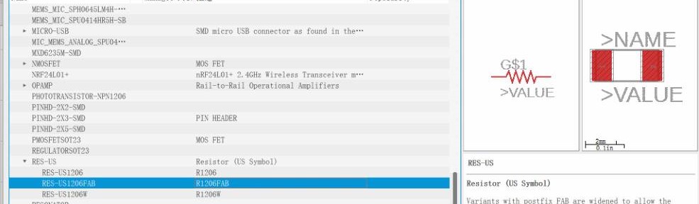
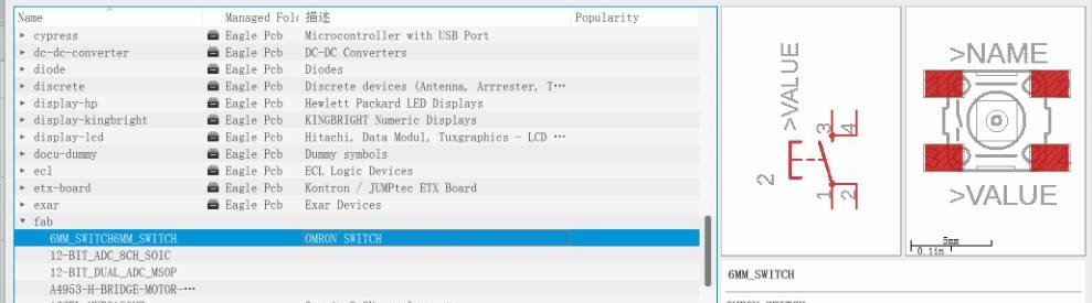
These are the components I use.
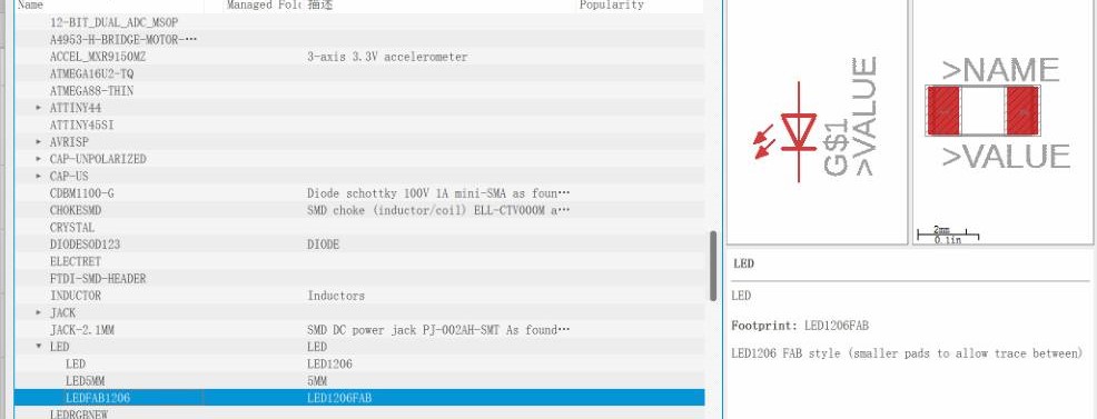
-
Before start design, and also, in order to use my board as an Arduino board with
Arduino IDE, I need a pinout diagram like this. (from Github_megaTinyCore)
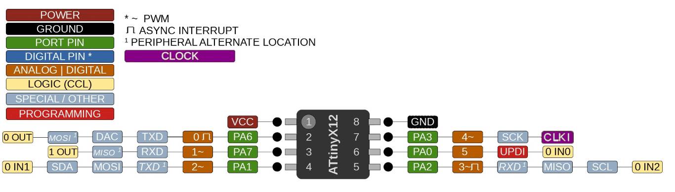
-
To design a LED and a button on board, the basic electronic knowledge you should learn is
pull-up and pull-down resistors, I recommend this one. -
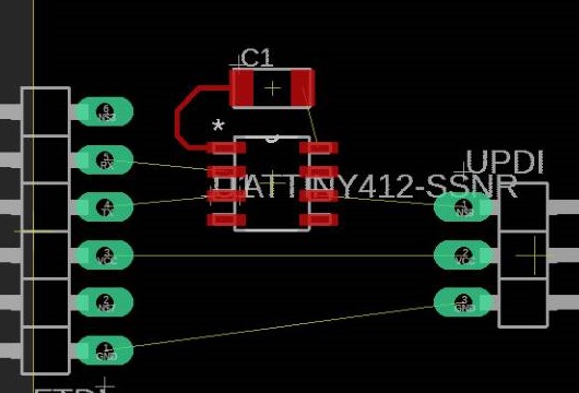
Add the components with
add parttool, and link them withnetornametool.
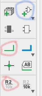
-
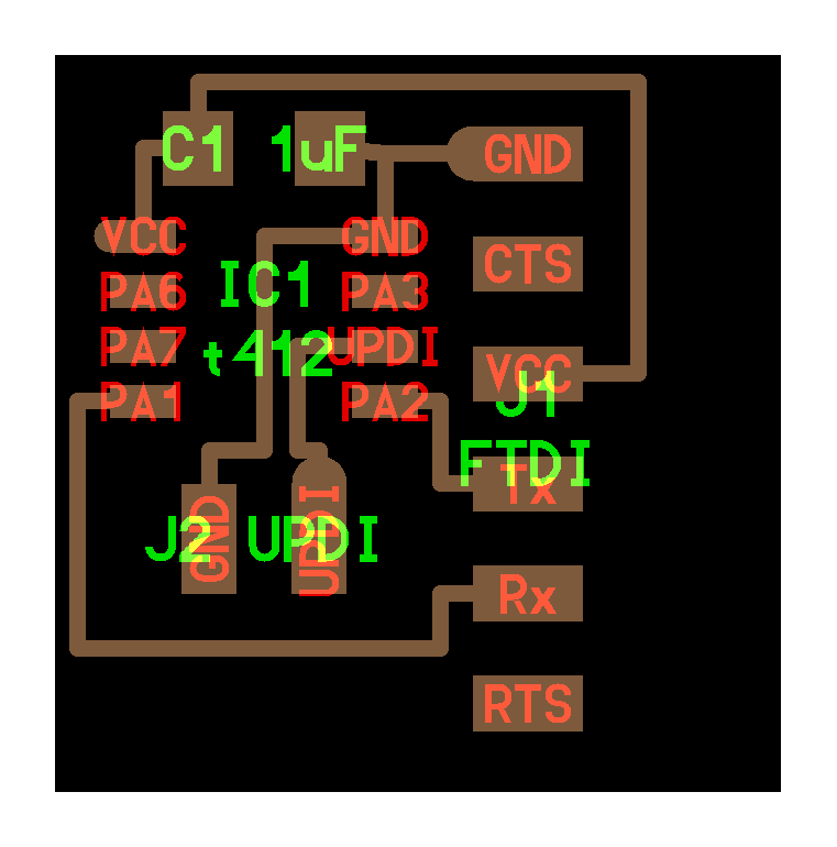
Finish the schematic.
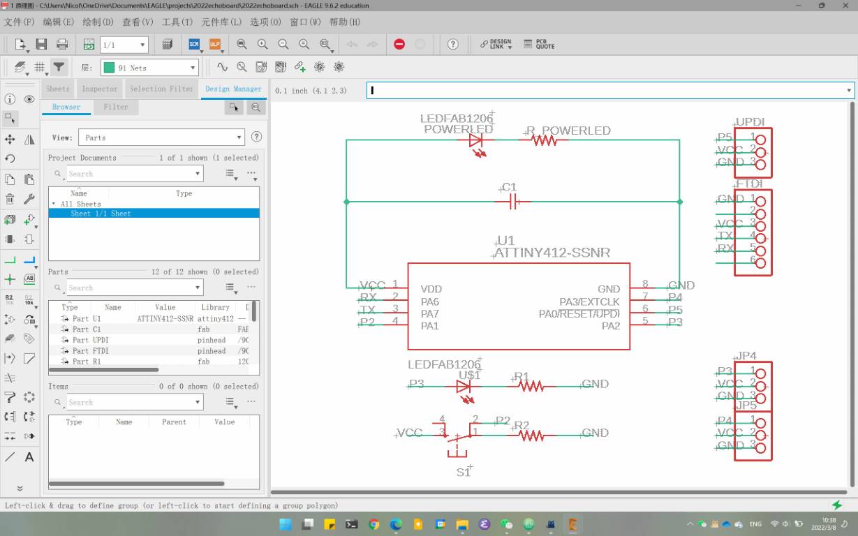
-
Click this gray and green button, it means switch to designing a board from schematic.
-
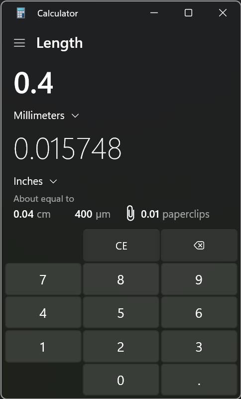
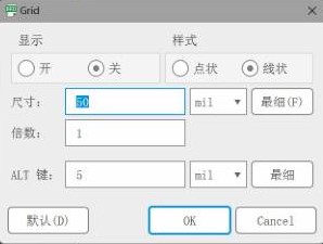
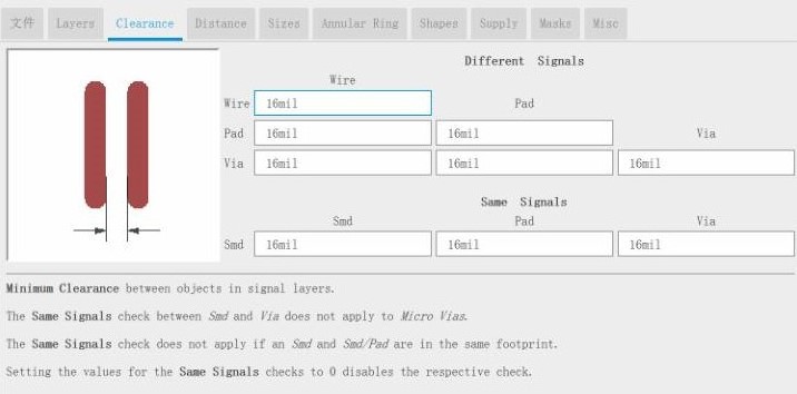
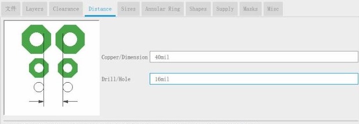
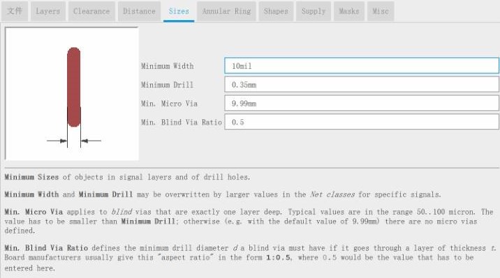
Preset before design the board, But why it is 16mil? Because our tracing endmill is 1/64 inch (15.625 mil), so the gaps must be bigger than that – the endmill will never mill the gap smaller than 1/64.
-
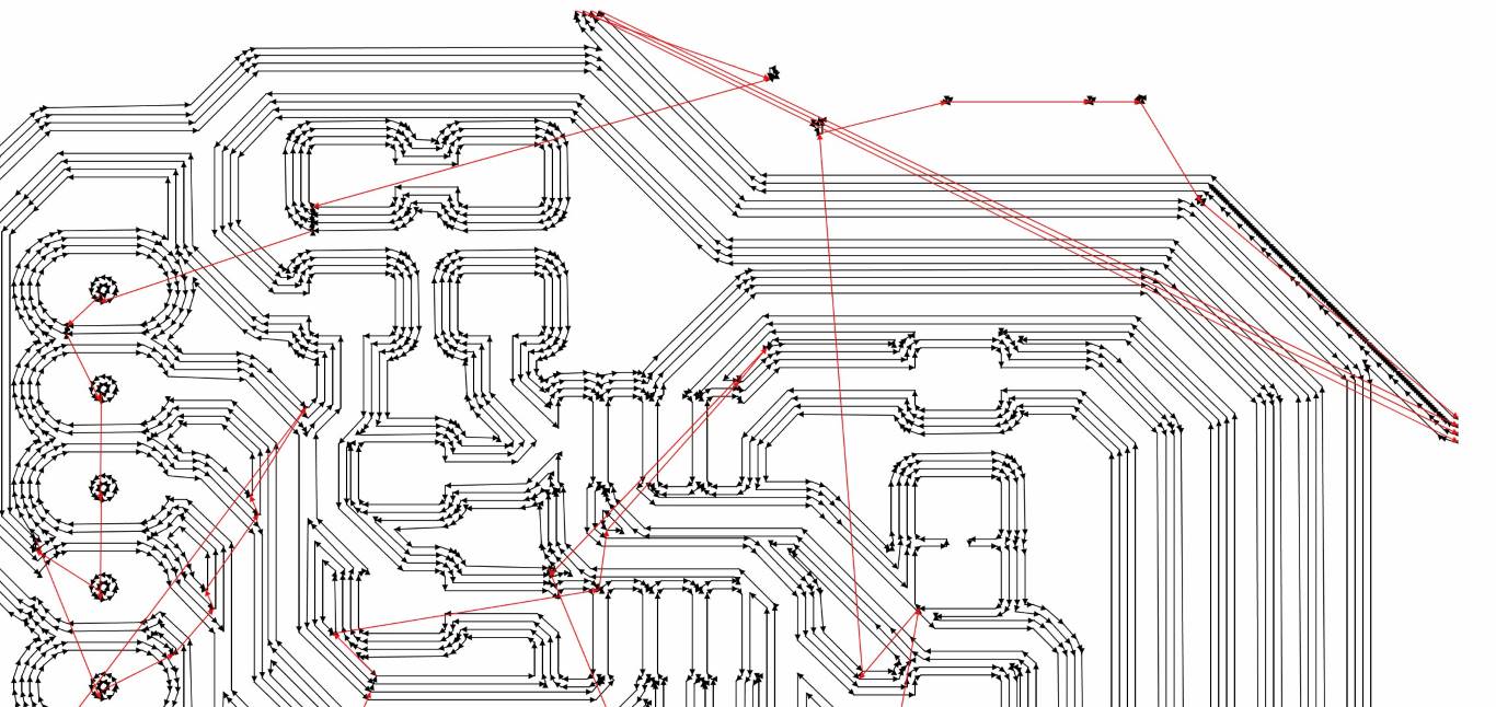
Use
Route Airwiretool orAuto Routertool to make thenet linebecome the ‘real wire‘
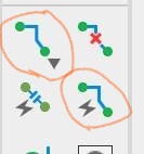
You can useRoute Airwireto connect like this,
you also can useAuto Routerlike this.(Make sure we only need the top layer)
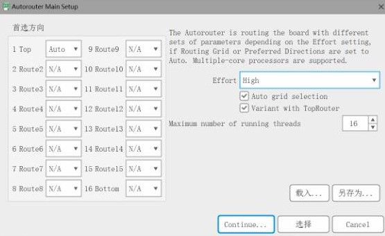
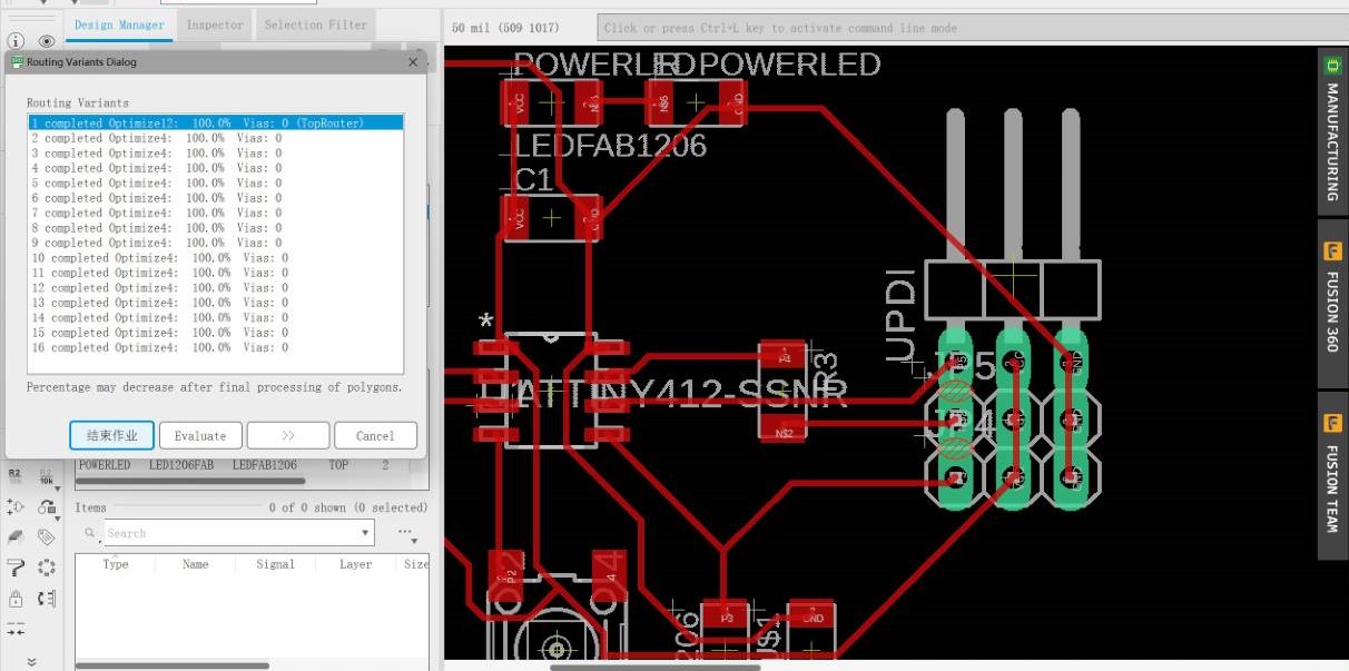
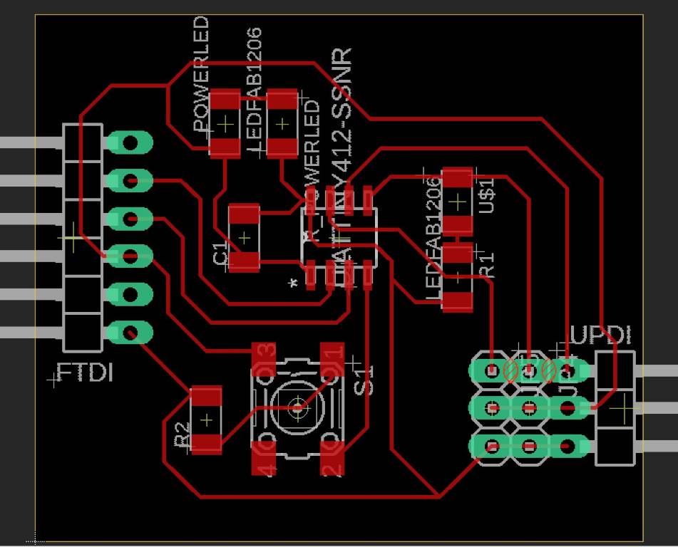
Remember: You must adjust the wire manually, to follow your CNC design rules. -
Finish the board design.
-
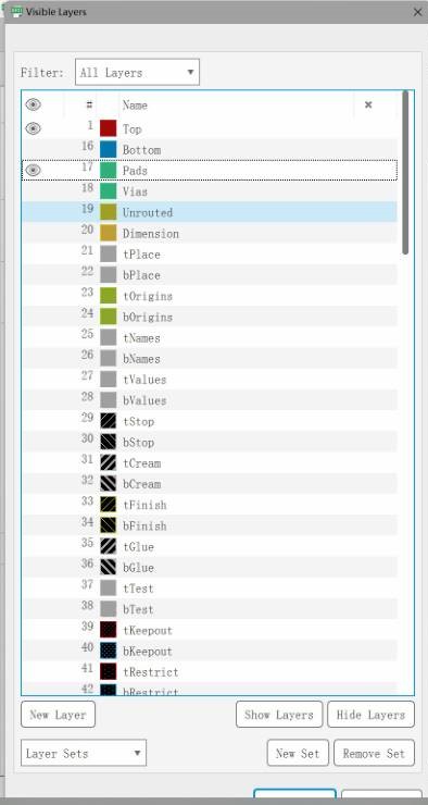
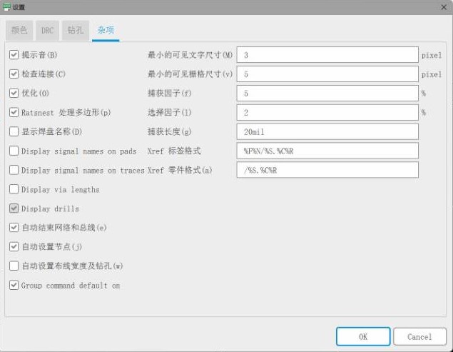
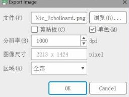
Before export the design as PNG, plz follow the setting below.
- Only display the Top and Pads layer.
- Only display the drills.
- The resolution is 1000dpi and click the mono checkbox.
- Remember the size.
-
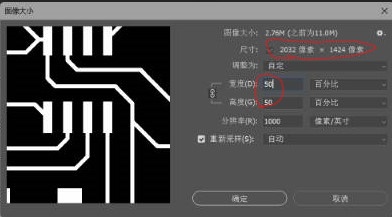
Import the PNG you just export from EAGLE to Photoshop, check the image size, make sure it is the same as you remembered in the EAGLE, if not, shrink it with 50%
-
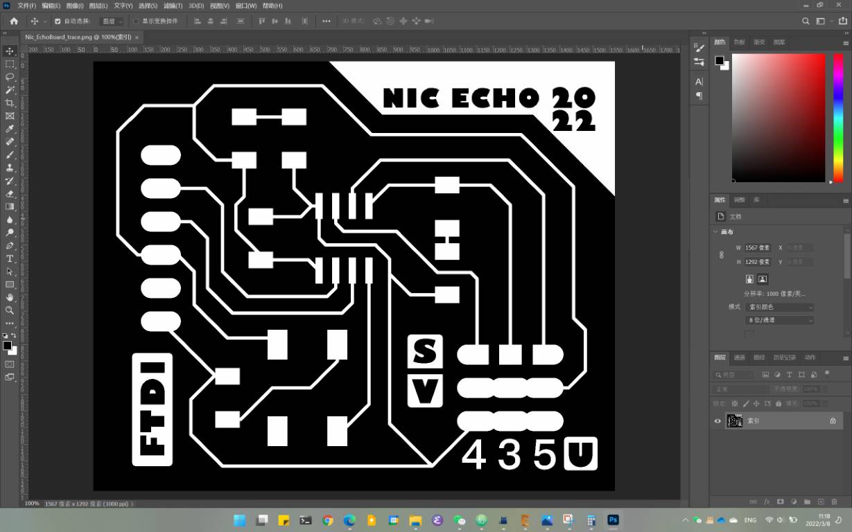
Photoshop workflow: Crop as you want, but never resize it. Save the image as
_trace_hole,_outlinefile, and modified them.- In the
_tracefile, delete the hole and name your board and write some note on it. Don’t forget follow your CNC rules. (such as, if the line of font is too thin?)
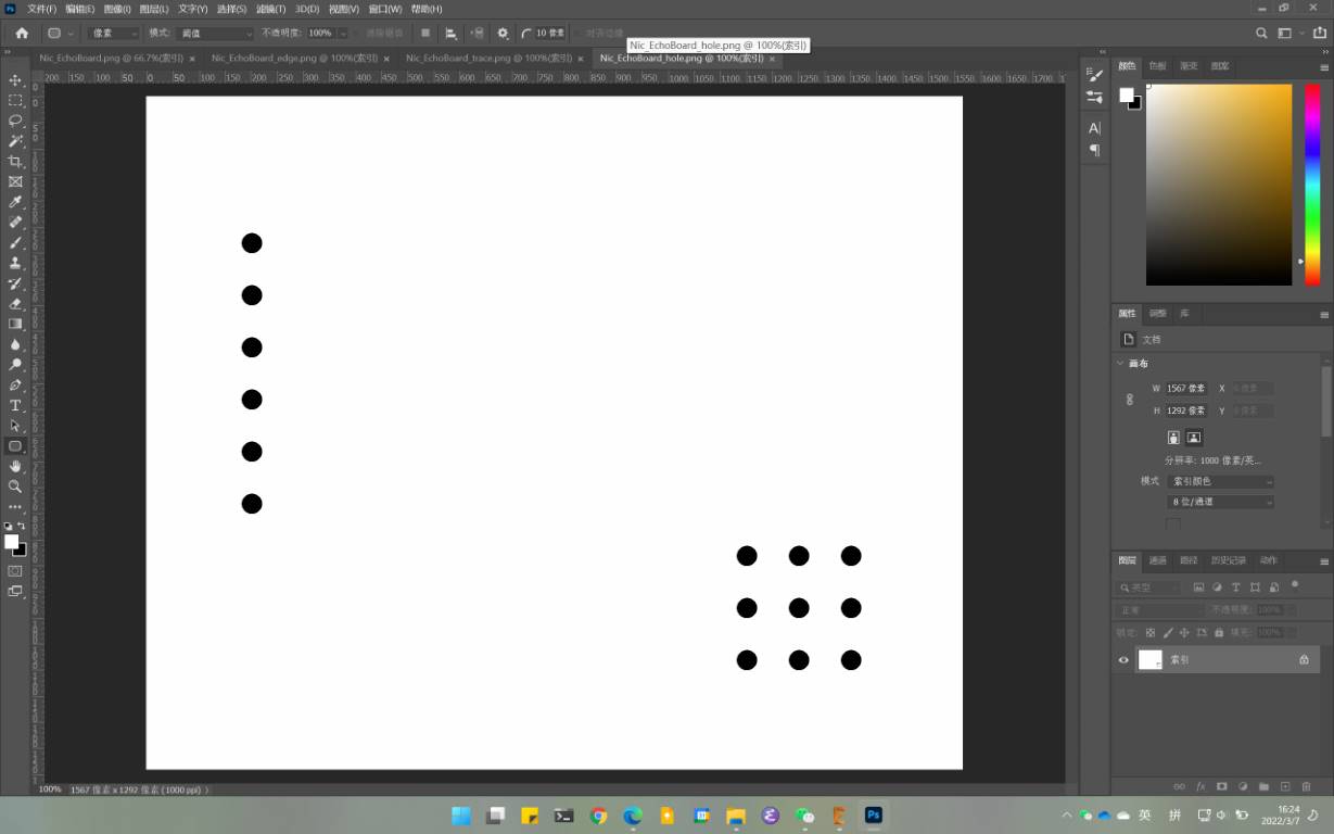
- In the
_holefile, delete all the black area except holes
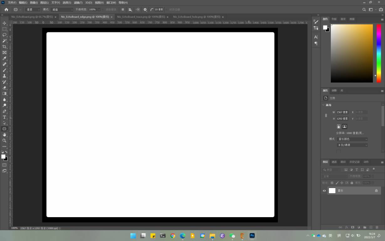
- In the
_outlinefile, design the edge of your board. (You can make it as a animal or a map, but I don’t do that)
- In the
-
Transform the PNG to the rml file with fab mods, as we did in week04. In this step, don’t forget to check all the traces and fonts, to make sure they will be cut correctly.
Here is a negative case: w06_eagle27
Mill and Solder my board
-
Mill as I did in week04, so I get:
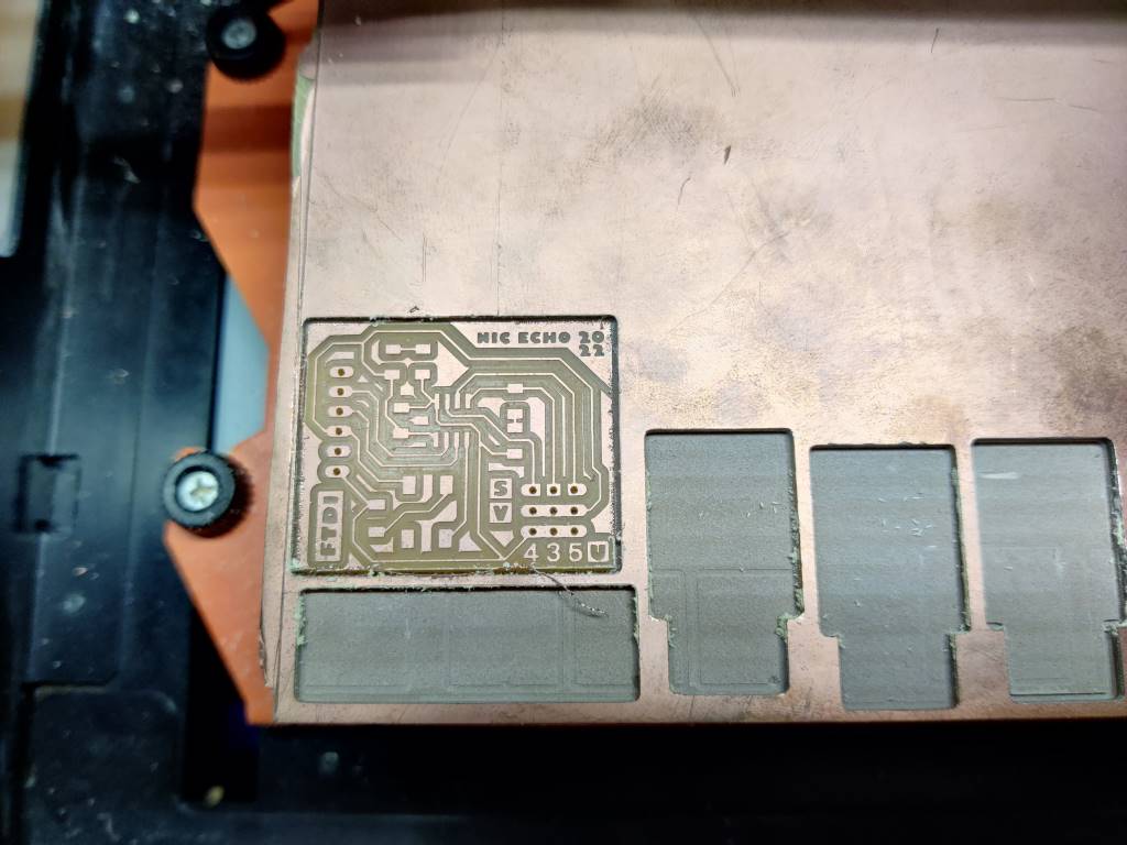
This time I set the speed at 30% (72mm/min), so it looks good this time. -
Choose components.
name value amount ATtiny412 - 1 Capacity 1 uF 1 Resistor 1k ohm 1 Resistor 499 ohm 1 Resistor 10k ohm 1 LED Green 1 LED Red 1 Button - 1 Pinhead 1*6 (90 degree) 1 Pinhead 1*3 (90 degree) 1 Pinhead 1*3 2
Here are the reference when I choose the value of resistor and capacity.
-
Speak of how to solder it, you can check my week04 assignment.
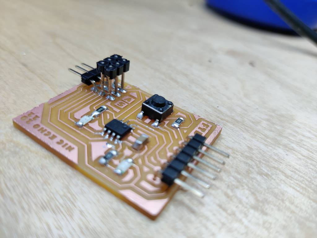
Here a funny thing is to solder the serried pinheads: I have to move the black part to the top, so that I can solder it ealier, then move it down.
like this:
-
Finish soldering
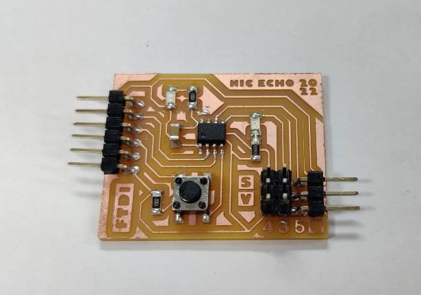
-
Plug my board to my computer, power supply success!
Ok I can program it.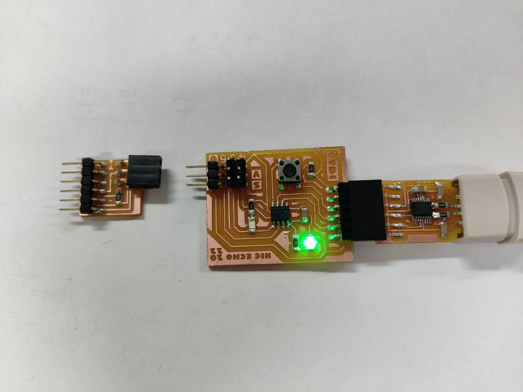
Program my board
-
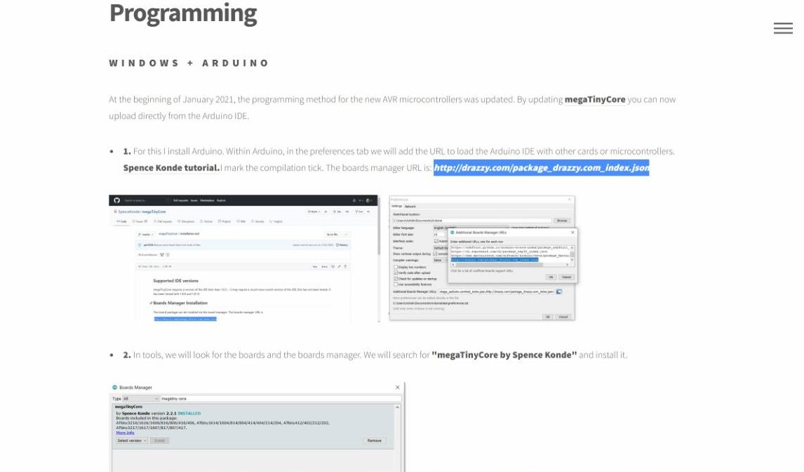
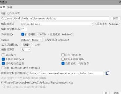
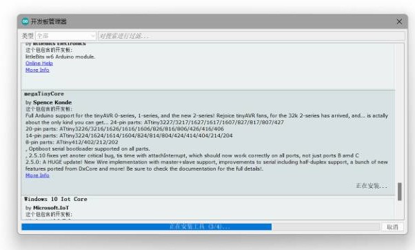
Before programming with Arduino, it is neccessary to install the library in Arduino.
I use the link which Adrian Torres mentioned in his assignment (Thanks!), and this link is also posted on Github megaTiny
-
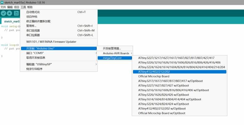
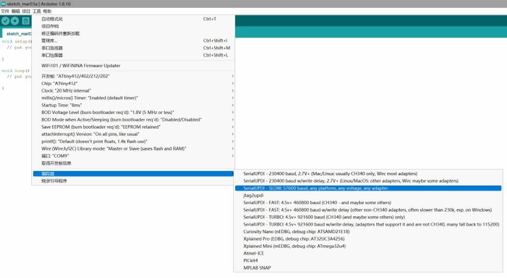
Connect my board and set port and board to ATtiny412, set programmer to FDTI-UPDI like this
-
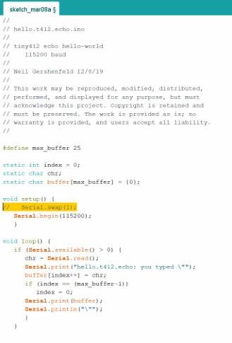
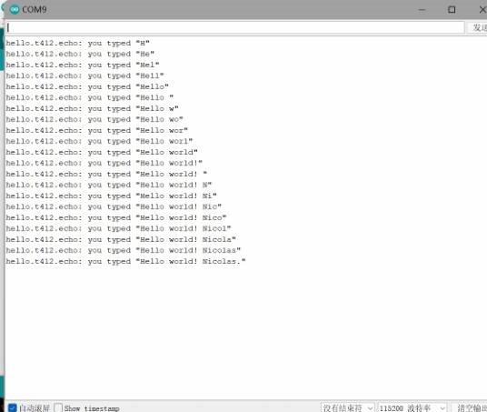
Echo test
Copy code from Neil, and commentSerial.swap(1)because I use Pin PA6 and PA7 to do the FTDI serial communication.
Download and test! Works well!
-
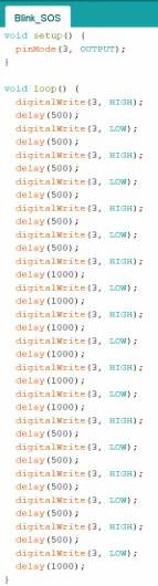
LED test
-
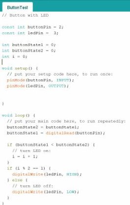
Button test with LED
Links & Files
- Tobin's w6: Our groupwork this week is on Tobin's site, Thanks for documenting!
- Print troubleshoot - Prusa: A powerful tool made by Neil. We use it to make .rml file for milling this week.
- Fab_Eagle_Tutorial: A brief but good tutorial to use EAGLE.
- Fab_Eagle_Resources: Where I download the library of EAGLE.
- Github_ATtinyx12: Where the ATtiny412 information is.
- Github_ATtinyx12_installation: Where the library of ATtiny412 for Arduino programming is.
- Pull-up/down resistors: Where you can have a brief learning about pull up and pull down resistors. Files this week
- All_In_One_3D_printer_test_micro (shared by Saverio): STL, Thanks!
- Nesting ring: The ring in a ring in a ring ... model I made. STL